
Owner's Manual (English)
Page 2
..., in particular, specifies that interference will not occur in a residential installation. REFER TO QUALIFIED SERVICE PERSONNEL. Consult the dealer or an experienced radio/TV technician for a Class B digital device, pursuant to Part 15 of the cable entry as close to constitute a risk of the following measures: - NO USER SERVICEABLE PARTS INSIDE. WARNING / CAUTION To prevent fire or shock hazards...
..., in particular, specifies that interference will not occur in a residential installation. REFER TO QUALIFIED SERVICE PERSONNEL. Consult the dealer or an experienced radio/TV technician for a Class B digital device, pursuant to Part 15 of the cable entry as close to constitute a risk of the following measures: - NO USER SERVICEABLE PARTS INSIDE. WARNING / CAUTION To prevent fire or shock hazards...
Owner's Manual (English)
Page 5
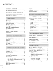
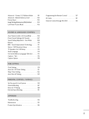
... 97 Manual Picture Adjustment - EZ Picture - Preset 95 - User Mode 98 - Color Tone - CONTENTS WARNING / CAUTION 1 SAFETY INSTRUCTION 2 TM TV GUIDE ON SCREEN NOTICES FOR U.S.A/ DIGITAL CABLE COMPATIBILITY . . . 6 FEATURES OF THIS TV 7 PREPARATION Accessories 8 Home Menu 9 Front Panel Controls 10 Back Panel Information 11 Attaching the TV to a Wall 12 Back Cover for Wire Arrangement 13 Vesa Wall Mounting 14 Desktop Pedestal Installation 15 Antenna or Cable Connection 16 TM CableCARD 17 EXTERNAL EQUIPMENT SETUP HD Receiver Setup 22 DVD Setup 25 VCR Setup...
... 97 Manual Picture Adjustment - EZ Picture - Preset 95 - User Mode 98 - Color Tone - CONTENTS WARNING / CAUTION 1 SAFETY INSTRUCTION 2 TM TV GUIDE ON SCREEN NOTICES FOR U.S.A/ DIGITAL CABLE COMPATIBILITY . . . 6 FEATURES OF THIS TV 7 PREPARATION Accessories 8 Home Menu 9 Front Panel Controls 10 Back Panel Information 11 Attaching the TV to a Wall 12 Back Cover for Wire Arrangement 13 Vesa Wall Mounting 14 Desktop Pedestal Installation 15 Antenna or Cable Connection 16 TM CableCARD 17 EXTERNAL EQUIPMENT SETUP HD Receiver Setup 22 DVD Setup 25 VCR Setup...
Owner's Manual (English)
Page 6
User Mode 108 Balance 110 BBE - Black( Darkness) Level 102 Picture Reset 103 Image Sticking Minimization( ISM) Method 104 Low-Power Picture Mode 105 Programming the Remote Control 137 IR Codes 141 External Control through RS-232C 143 SOUND & LANGUAGE CONTROL Auto Volume Leveler ( EZ SoundRite 106 Preset Sound Settings( EZ Sound 107 Sound Setting Adjustment - Cinema 3:2 Pulldown Mode . . . . . 101 Advanced - Sound Improvement Technology 111 Stereo / SAP Broadcast Setup 112 TV Speakers On/ Off Setup 113 Audio Language 114 On-Screen Menus Lanaguage Selection 115...
User Mode 108 Balance 110 BBE - Black( Darkness) Level 102 Picture Reset 103 Image Sticking Minimization( ISM) Method 104 Low-Power Picture Mode 105 Programming the Remote Control 137 IR Codes 141 External Control through RS-232C 143 SOUND & LANGUAGE CONTROL Auto Volume Leveler ( EZ SoundRite 106 Preset Sound Settings( EZ Sound 107 Sound Setting Adjustment - Cinema 3:2 Pulldown Mode . . . . . 101 Advanced - Sound Improvement Technology 111 Stereo / SAP Broadcast Setup 112 TV Speakers On/ Off Setup 113 Audio Language 114 On-Screen Menus Lanaguage Selection 115...

Owner's Manual (English)
Page 7
...,121. High-definition television. High-resolution digital television broadcast and playback system composed of Deployment) access cards, also called CableCARDs, that connect audio and video devices with one remote control. Patent Notice The TV Guide On ScreenTM system is required to a cable system providing such programming. Use of Cable Television Laboratories, Inc." A security card provided by direct connection to view encrypted digital programming. For more pixels, 16:9 aspect-ratio screens, and AC3 digital audioR . Trademark...
...,121. High-definition television. High-resolution digital television broadcast and playback system composed of Deployment) access cards, also called CableCARDs, that connect audio and video devices with one remote control. Patent Notice The TV Guide On ScreenTM system is required to a cable system providing such programming. Use of Cable Television Laboratories, Inc." A security card provided by direct connection to view encrypted digital programming. For more pixels, 16:9 aspect-ratio screens, and AC3 digital audioR . Trademark...
Owner's Manual (English)
Page 12
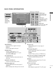
... Connect a HDMI signal to the 1 or 2 port with AC power. COMPONENT IN Connect a component video/audio device to the RS-232C port on DC power. 11 RS-232C IN (CONTROL & SERVICE) PORT Connect to these ports do not work. CABLE IN Connect cable signals to various types of equipment. Note: In standby mode, these jacks. REMOTE CONTROL IN Connect your wired remote control. AUDIO OUT Connect analog audio to this jack. ANTENNA IN Connect over-the air signals to the appropriate input port. RGB IN Connect the monitor output from various types of equipment. DIGITAL...
... Connect a HDMI signal to the 1 or 2 port with AC power. COMPONENT IN Connect a component video/audio device to the RS-232C port on DC power. 11 RS-232C IN (CONTROL & SERVICE) PORT Connect to these ports do not work. CABLE IN Connect cable signals to various types of equipment. Note: In standby mode, these jacks. REMOTE CONTROL IN Connect your wired remote control. AUDIO OUT Connect analog audio to this jack. ANTENNA IN Connect over-the air signals to the appropriate input port. RGB IN Connect the monitor output from various types of equipment. DIGITAL...
Owner's Manual (English)
Page 23
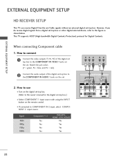
... the digital set top box to COMPONENT IN 2 input, select COMPONENT 2 input source. Match the jack colors (Y = green, PB = blue, and PR = red). 2 Connect the audio output of the digital set -top box to the COMPONENT IN AUDIO 1 jacks on the remote control. When connecting Component cable 1. I Select COMPONENT 1 input source with using the INPUT button on the set -top box. (Refer to the figure as shown below. EXTERNAL EQUIPMENT SETUP EXTERNAL EQUIPMENT SETUP HD RECEIVER SETUP This TV can receive Digital Over-the-air/Cable signals without an external digital set . This TV supports...
... the digital set top box to COMPONENT IN 2 input, select COMPONENT 2 input source. Match the jack colors (Y = green, PB = blue, and PR = red). 2 Connect the audio output of the digital set -top box to the COMPONENT IN AUDIO 1 jacks on the remote control. When connecting Component cable 1. I Select COMPONENT 1 input source with using the INPUT button on the set -top box. (Refer to the figure as shown below. EXTERNAL EQUIPMENT SETUP EXTERNAL EQUIPMENT SETUP HD RECEIVER SETUP This TV can receive Digital Over-the-air/Cable signals without an external digital set . This TV supports...
Owner's Manual (English)
Page 24
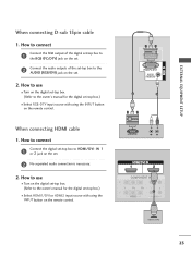
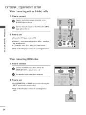
...) jack on the set. 2 Connect the audio outputs of the set-top box to the owner's manual for the digital set . 2 No separated audio connection is necessary. 2. When connecting HDMI cable 1. RGB OUTPUT L R L R AUDIO HDMI-DTV OUTPUT 23 EXTERNAL EQUIPMENT SETUP When connecting D-sub 15pin cable 1. How to use I Turn on the digital set-top box. (Refer to HDMI/DVI IN 1 or 2 jack on the set -top box.) I Select RGB-DTV input source with using the INPUT button on the remote control. How to use I Turn on the digital set-top box. (Refer to the AUDIO (RGB/DVI) jack...
...) jack on the set. 2 Connect the audio outputs of the set-top box to the owner's manual for the digital set . 2 No separated audio connection is necessary. 2. When connecting HDMI cable 1. RGB OUTPUT L R L R AUDIO HDMI-DTV OUTPUT 23 EXTERNAL EQUIPMENT SETUP When connecting D-sub 15pin cable 1. How to use I Turn on the digital set-top box. (Refer to HDMI/DVI IN 1 or 2 jack on the set -top box.) I Select RGB-DTV input source with using the INPUT button on the remote control. How to use I Turn on the digital set-top box. (Refer to the AUDIO (RGB/DVI) jack...
Owner's Manual (English)
Page 25
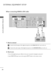
How to connect DVI-DTV OUTPUT L R 1 Connect the DVI output of the digital set-top box to the HDMI/DVI IN 1 jack on the set. 2 Connect the audio output of the digital set-top box to DVI cable EXTERNAL EQUIPMENT SETUP AUDIO 1. EXTERNAL EQUIPMENT SETUP When connecting HDMI to the AUDIO(RGB/DVI) jack on the set. 2. How to use I Turn on the digital set-top box. (Refer to the owner's manual for the digital set-top box.) I Select HDMI1/DVI input source with using the INPUT button on the remote control. 24
How to connect DVI-DTV OUTPUT L R 1 Connect the DVI output of the digital set-top box to the HDMI/DVI IN 1 jack on the set. 2 Connect the audio output of the digital set-top box to DVI cable EXTERNAL EQUIPMENT SETUP AUDIO 1. EXTERNAL EQUIPMENT SETUP When connecting HDMI to the AUDIO(RGB/DVI) jack on the set. 2. How to use I Turn on the digital set-top box. (Refer to the owner's manual for the digital set-top box.) I Select HDMI1/DVI input source with using the INPUT button on the remote control. 24
Owner's Manual (English)
Page 26
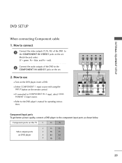
I If connected to COMPONENT IN 2 input, select COM- I Select COMPONENT 1 input source with using the INPUT button on the remote control. Component ports on the TV Y PB PR Video output ports on the set . AUDIO EXTERNAL EQUIPMENT SETUP DVD SETUP When connecting Component cable 1. How to use I Refer to the COMPONENT IN VIDEO1 jacks on the DVD player, insert a DVD. I Turn on the set . 2. tions. Match the jack colors (Y = green, PB = blue, and PR = red). 2 Connect the audio outputs of the DVD to the DVD player's manual for operating instruc- PONENT 2 input source....
I If connected to COMPONENT IN 2 input, select COM- I Select COMPONENT 1 input source with using the INPUT button on the remote control. Component ports on the TV Y PB PR Video output ports on the set . AUDIO EXTERNAL EQUIPMENT SETUP DVD SETUP When connecting Component cable 1. How to use I Refer to the COMPONENT IN VIDEO1 jacks on the DVD player, insert a DVD. I Turn on the set . 2. tions. Match the jack colors (Y = green, PB = blue, and PR = red). 2 Connect the audio outputs of the DVD to the DVD player's manual for operating instruc- PONENT 2 input source....
Owner's Manual (English)
Page 27
...HDMI-DVD OUTPUT EXTERNAL EQUIPMENT SETUP EXTERNAL EQUIPMENT SETUP When connecting with using the INPUT button on the remote control. I Refer to the HDMI/DVI IN1 or 2 jack on the set . 2 No separated audio connection is necessary. 2. How to connect 1 Connect the HDMI output of the DVD to AV IN 2, select A V 2 input source. How to connect 1 Connect the S-VIDEO output of the DVD to the S-VIDEO input on the set. 2 Connect the audio outputs of the DVD to the DVD player's manual for operating instructions. When connecting HDMI cable 1. I If connected to the AUDIO input jacks...
...HDMI-DVD OUTPUT EXTERNAL EQUIPMENT SETUP EXTERNAL EQUIPMENT SETUP When connecting with using the INPUT button on the remote control. I Refer to the HDMI/DVI IN1 or 2 jack on the set . 2 No separated audio connection is necessary. 2. How to connect 1 Connect the HDMI output of the DVD to AV IN 2, select A V 2 input source. How to connect 1 Connect the S-VIDEO output of the DVD to the S-VIDEO input on the set. 2 Connect the audio outputs of the DVD to the DVD player's manual for operating instructions. When connecting HDMI cable 1. I If connected to the AUDIO input jacks...
Owner's Manual (English)
Page 33
... connected with HDMI/DVI Input, output TV SET Resolution (480p, 720p, 1080i) and TV SET Display fit EIA/CEA-861-B Specification to the Cable or if there is a poor cable connection, "No signal" is displayed, refer to 1024x768, 60Hz. If not, refer to adjust the screen Position of the TV SET and contact a PC graphics card service center. As shown in the picture, press the ADJUST button to the Manual of time. If "Invalid Format...
... connected with HDMI/DVI Input, output TV SET Resolution (480p, 720p, 1080i) and TV SET Display fit EIA/CEA-861-B Specification to the Cable or if there is a poor cable connection, "No signal" is displayed, refer to 1024x768, 60Hz. If not, refer to adjust the screen Position of the TV SET and contact a PC graphics card service center. As shown in the picture, press the ADJUST button to the Manual of time. If "Invalid Format...
Owner's Manual (English)
Page 36
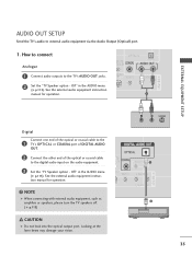
... COAXIAL port of DIGITAL AUDIO OUT. 2 Connect the other end of the optical or coaxial cable to the TV's AUDIO OUT jacks. 2 Set the "TV Speaker option - Looking at the laser beam may damage your vision. Off" in the AUDIO menu. (G p.113). L R S-VIDEO 35 How to connect Analogue 1 Connect audio outputs to the digital audio input on the audio equipment. 3 Set the "TV Speaker option - Off" in the AUDIO menu. (G p.113). See the external audio equipment instruction manual for operation...
... COAXIAL port of DIGITAL AUDIO OUT. 2 Connect the other end of the optical or coaxial cable to the TV's AUDIO OUT jacks. 2 Set the "TV Speaker option - Looking at the laser beam may damage your vision. Off" in the AUDIO menu. (G p.113). L R S-VIDEO 35 How to connect Analogue 1 Connect audio outputs to the digital audio input on the audio equipment. 3 Set the "TV Speaker option - Off" in the AUDIO menu. (G p.113). See the external audio equipment instruction manual for operation...
Owner's Manual (English)
Page 42
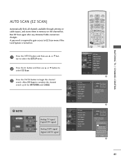
... to gain access to EZ Scan menu if the Lock System is turned on the channel list. DAY + SIMPLINK EZ Scan Manual Scan Channel Edit DTV Signal Main Input Sub Input Input Label Set ID EZ Scan Manual Scan Channel Edit DTV Signal Main Input Sub Input Input Label Set ID G Selection ( G or ) leads you to the EZ scan screen. NOTE Analog TV signal Digital DTV signal Analog CATV signal Digital CADTV signal LIVE TV INPUT MODE DAY - WATCHING TV / CHANNEL CONTROL AUTO SCAN (EZ SCAN) Automatically finds all channels available through antenna or cable inputs, and...
... to gain access to EZ Scan menu if the Lock System is turned on the channel list. DAY + SIMPLINK EZ Scan Manual Scan Channel Edit DTV Signal Main Input Sub Input Input Label Set ID EZ Scan Manual Scan Channel Edit DTV Signal Main Input Sub Input Input Label Set ID G Selection ( G or ) leads you to the EZ scan screen. NOTE Analog TV signal Digital DTV signal Analog CATV signal Digital CADTV signal LIVE TV INPUT MODE DAY - WATCHING TV / CHANNEL CONTROL AUTO SCAN (EZ SCAN) Automatically finds all channels available through antenna or cable inputs, and...
Owner's Manual (English)
Page 55
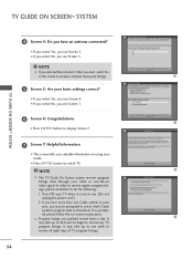
... week to one Cable system in this screen to display Screen 7. 7 Screen 7: Helpful Information I This screen tells you see Screen 6. NOTE The TV Guide On Screen system receives program listings data through your TV when it is not in Screen 3 then you see Screen 5. Turn OFF your cable or over-the-air video signal. Program listings are updated several times a day. NOTE If you selected No in use. (Do not unplug the power cord.) 2. It may...
... week to one Cable system in this screen to display Screen 7. 7 Screen 7: Helpful Information I This screen tells you see Screen 6. NOTE The TV Guide On Screen system receives program listings data through your TV when it is not in Screen 3 then you see Screen 5. Turn OFF your cable or over-the-air video signal. Program listings are updated several times a day. NOTE If you selected No in use. (Do not unplug the power cord.) 2. It may...
Owner's Manual (English)
Page 67
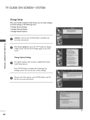
... Guide settings in the following areas: I Change System Settings I Change Channel Display I Change Default Options 1 Highlight a choice, press ENTER button, and follow the on -screen instructions. 2 With Setup highlighted, press the INFO button to close the screen. TV GUIDE ON SCREENTM SYSTEM TV GUIDE ON SCREENTM SYSTEM Change Setup After you initially complete Guide Setup, you have completed the initial Guide Setup process. Press the INFO button again to display a Help screen. Press ENTER button to display the Confirming Your Settings screen. Change...
... Guide settings in the following areas: I Change System Settings I Change Channel Display I Change Default Options 1 Highlight a choice, press ENTER button, and follow the on -screen instructions. 2 With Setup highlighted, press the INFO button to close the screen. TV GUIDE ON SCREENTM SYSTEM TV GUIDE ON SCREENTM SYSTEM Change Setup After you initially complete Guide Setup, you have completed the initial Guide Setup process. Press the INFO button again to display a Help screen. Press ENTER button to display the Confirming Your Settings screen. Change...
Owner's Manual (English)
Page 125
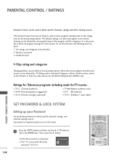
... or direct-to select the LOCK menu. A password is also possible to be viewed. The Parental Control Function (V-Chip) is set up blocking schemes to block program viewing based on the ratings sent by broadcasting stations. PARENTAL CONTROL / RATINGS Parental Control can be blocked by choosing the type of the program and the categories. Then, press the G button. SIMPLINK I The TV is used to block specific channels, ratings and other viewing sources. Set ratings...
... or direct-to select the LOCK menu. A password is also possible to be viewed. The Parental Control Function (V-Chip) is set up blocking schemes to block program viewing based on the ratings sent by broadcasting stations. PARENTAL CONTROL / RATINGS Parental Control can be blocked by choosing the type of the program and the categories. Then, press the G button. SIMPLINK I The TV is used to block specific channels, ratings and other viewing sources. Set ratings...
Owner's Manual (English)
Page 126
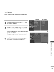
... new. Set Password Change the password by inputting a new password twice. 1 After inputting the password, use the D or E button to choose Set password. 2 Press the G button and then choose any 4 digits for your changed password has been memorized. 3 Press EXIT button to return to TV viewing or press MENU button to return to the previous menu. Then your new password and enter the them on the Confirm. For USA Lock System Set Password Block Channel Movie...
... new. Set Password Change the password by inputting a new password twice. 1 After inputting the password, use the D or E button to choose Set password. 2 Press the G button and then choose any 4 digits for your changed password has been memorized. 3 Press EXIT button to return to TV viewing or press MENU button to return to the previous menu. Then your new password and enter the them on the Confirm. For USA Lock System Set Password Block Channel Movie...
Owner's Manual (English)
Page 133
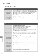
... electrical appliance or power tool. I Adjust Color in . The problem may be with correct polarity (+ to another product's power cord into wall power outlet? I Station signal is suddenly turned off activated. 132 APPENDIX The video function does not work. Power is weak, reorient antenna to -). No or poor color or poor picture I Keep a sufficient distance between the product and the remote control causing obstruction. I Is the sleep timer set : TV, VCR etc.
... electrical appliance or power tool. I Adjust Color in . The problem may be with correct polarity (+ to another product's power cord into wall power outlet? I Station signal is suddenly turned off activated. 132 APPENDIX The video function does not work. Power is weak, reorient antenna to -). No or poor color or poor picture I Keep a sufficient distance between the product and the remote control causing obstruction. I Is the sleep timer set : TV, VCR etc.
Owner's Manual (English)
Page 138
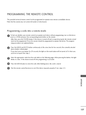
... selected device button is stored. 5 Test the remote control functions to store the code. When pressing the button, the light blinks at the same time for 20 seconds, the light on the mode button will be programmed. After that case, you don't press any button for two seconds; After blinking twice, this code is illuminated. In that , press the POWER button. If the device turned off . PROGRAMMING THE REMOTE CONTROL The provided universal remote control...
... selected device button is stored. 5 Test the remote control functions to store the code. When pressing the button, the light blinks at the same time for 20 seconds, the light on the mode button will be programmed. After that case, you don't press any button for two seconds; After blinking twice, this code is illuminated. In that , press the POWER button. If the device turned off . PROGRAMMING THE REMOTE CONTROL The provided universal remote control...
Owner's Manual (English)
Page 151
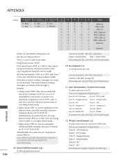
... and minor channel number in case digital channel tuning. 3. Analog channel: NTSC cable, channel number(35), main picture Command: ma 00 23 xx xx xx xx 01 attribute(0x01): main picture, two part(it's not mandatory), using physical channel bit must be done by Hexadecimal code * Two/One part Channel: 6th bit This bit is used in PIP mode. PIP Input Select(Command: x y) To adjust input source for TV. Digital channel: ATSC air, channel number(physical(20...
... and minor channel number in case digital channel tuning. 3. Analog channel: NTSC cable, channel number(35), main picture Command: ma 00 23 xx xx xx xx 01 attribute(0x01): main picture, two part(it's not mandatory), using physical channel bit must be done by Hexadecimal code * Two/One part Channel: 6th bit This bit is used in PIP mode. PIP Input Select(Command: x y) To adjust input source for TV. Digital channel: ATSC air, channel number(physical(20...


