
Owner's Manual (English)
Page 15
... to operate the TV on DC power. 15 This port is used for audio. 9 Power Cord Socket For operation with amps and home theater systems. Note: In standby mode, this port doesn't work. 6 ANTENNA/CABLE IN Connect over-the air signals to this jack. 7 RS-232C...4 RGB IN (PC) Analog PC Connection. Doesn't support 480i. AUDIO IN (RGB/DVI) 1/8" (0.32 cm) headphone jack for analog PC audio input. 5 OPTICAL DIGITAL AUDIO OUT (Except 19/22LH20, 22LH200C) Digital optical audio output for software updates. 2 AV (Audio/Video) IN Analog composite connection. PREPARATION 1 USB IN SERVICE ONLY ...
... to operate the TV on DC power. 15 This port is used for audio. 9 Power Cord Socket For operation with amps and home theater systems. Note: In standby mode, this port doesn't work. 6 ANTENNA/CABLE IN Connect over-the air signals to this jack. 7 RS-232C...4 RGB IN (PC) Analog PC Connection. Doesn't support 480i. AUDIO IN (RGB/DVI) 1/8" (0.32 cm) headphone jack for analog PC audio input. 5 OPTICAL DIGITAL AUDIO OUT (Except 19/22LH20, 22LH200C) Digital optical audio output for software updates. 2 AV (Audio/Video) IN Analog composite connection. PREPARATION 1 USB IN SERVICE ONLY ...
Owner's Manual (English)
Page 32
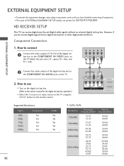
... EQUIPMENT SETUP EXTERNAL EQUIPMENT SETUP I This part of EXTERNAL EQUIPMENT SETUP mainly use I Select the Component input source on the TV using the INPUT button on the TV. 2. Match the jack colors (Y = green, PB = blue, and PR = red). How to connect 1 Connect the video outputs (Y, PB...to the COMPONENT IN AUDIO jacks on the remote control. 1 2 USB IN SERVICE ONLY AV IN VIDEO AUDIO L(MONO) R 2 VIDEO L R AUDIO 1 COMPONENT IN /DVI IN Supported Resolutions Signal Component 480i Yes 480p Yes 720p Yes 1080i Yes 1080p Yes HDMI No Yes Yes Yes Yes 32 Y, CB/PB,...
... EQUIPMENT SETUP EXTERNAL EQUIPMENT SETUP I This part of EXTERNAL EQUIPMENT SETUP mainly use I Select the Component input source on the TV using the INPUT button on the TV. 2. Match the jack colors (Y = green, PB = blue, and PR = red). How to connect 1 Connect the video outputs (Y, PB...to the COMPONENT IN AUDIO jacks on the remote control. 1 2 USB IN SERVICE ONLY AV IN VIDEO AUDIO L(MONO) R 2 VIDEO L R AUDIO 1 COMPONENT IN /DVI IN Supported Resolutions Signal Component 480i Yes 480p Yes 720p Yes 1080i Yes 1080p Yes HDMI No Yes Yes Yes Yes 32 Y, CB/PB,...
Owner's Manual (English)
Page 33
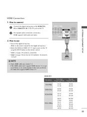
...the INPUT button on the TV. 2 No separate audio connection is necessary. In this case use I Turn on the digital set-top box. (Refer to the owner's manual for the digital set -top box to connect 1 Connect the digital set -top box.) I N or HDMI/DVI IN 1/2*/ 3* jack on the remote control.... * HDMI 2: Except 19/22LH20, 22LH200C * HDMI 3: Except 19/22/26/32/37/42LH20, 19/22LU55, 32CL20 ! EXTERNAL EQUIPMENT SETUP HDMI Connection 1. If the HDMI cables don't support HDMI ...
...the INPUT button on the TV. 2 No separate audio connection is necessary. In this case use I Turn on the digital set-top box. (Refer to the owner's manual for the digital set -top box to connect 1 Connect the digital set -top box.) I N or HDMI/DVI IN 1/2*/ 3* jack on the remote control.... * HDMI 2: Except 19/22LH20, 22LH200C * HDMI 3: Except 19/22/26/32/37/42LH20, 19/22LU55, 32CL20 ! EXTERNAL EQUIPMENT SETUP HDMI Connection 1. If the HDMI cables don't support HDMI ...
Owner's Manual (English)
Page 34
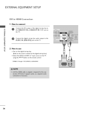
... is required for the digital set-top box.) I Select the HDMI or HDMI1/2* input source on the TV using the INPUT button on the TV. NOTE G A DVI to the AUDIO IN (RGB/DVI) jack on the remote control. * HDMI 2: Except 19/22LH20, 22LH200C ! EXTERNAL EQUIPMENT SETUP EXTERNAL EQUIPMENT SETUP DVI to the owner's manual...
... is required for the digital set-top box.) I Select the HDMI or HDMI1/2* input source on the TV using the INPUT button on the TV. NOTE G A DVI to the AUDIO IN (RGB/DVI) jack on the remote control. * HDMI 2: Except 19/22LH20, 22LH200C ! EXTERNAL EQUIPMENT SETUP EXTERNAL EQUIPMENT SETUP DVI to the owner's manual...
Owner's Manual (English)
Page 35
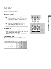
...2 USB IN SERVICE ONLY AV IN VIDEO AUDIO L(MONO) R 2 VIDEO L R AUDIO 1 COMPONENT IN A ( /DVI IN 35 Y PB PR L R 2 Connect the audio outputs of the DVD to the COMPONENT IN VIDEO jacks on the TV. 2. How to the COMPONENT IN AUDIO jacks on the TV. I Refer to the component input ports as... shown below. Component ports on the TV Y Y Video output ports Y on the remote control...
...2 USB IN SERVICE ONLY AV IN VIDEO AUDIO L(MONO) R 2 VIDEO L R AUDIO 1 COMPONENT IN A ( /DVI IN 35 Y PB PR L R 2 Connect the audio outputs of the DVD to the COMPONENT IN VIDEO jacks on the TV. 2. How to the COMPONENT IN AUDIO jacks on the TV. I Refer to the component input ports as... shown below. Component ports on the TV Y Y Video output ports Y on the remote control...
Owner's Manual (English)
Page 36
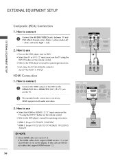
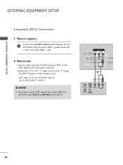
... Except 19/22LH20, 22LH200C * HDMI 3: Except 19/22/26/32/37/42LH20, 19/22LU55, 32CL20 ! Match the jack colors (Video = yellow, Audio Left = white, and Audio Right = red). 2. I Refer to use I Select the A V or AV1/2* input source on the TV using the INPUT button on the DVD player, insert a DVD....for operating instructions. * AV2: Only 32/37/42/47LH30, 26LU55, 32/37/42/47LF11, 47LF21 HDMI Connection 1. NOTE G Check HDMI cable over version 1.3. How to connect 1 Connect the HDMI output of the DVD to connect 1 Connect the AUDIO/VIDEO jacks between TV and DVD. How to the HDMI...
... Except 19/22LH20, 22LH200C * HDMI 3: Except 19/22/26/32/37/42LH20, 19/22LU55, 32CL20 ! Match the jack colors (Video = yellow, Audio Left = white, and Audio Right = red). 2. I Refer to use I Select the A V or AV1/2* input source on the TV using the INPUT button on the DVD player, insert a DVD....for operating instructions. * AV2: Only 32/37/42/47LH30, 26LU55, 32/37/42/47LF11, 47LF21 HDMI Connection 1. NOTE G Check HDMI cable over version 1.3. How to connect 1 Connect the HDMI output of the DVD to connect 1 Connect the AUDIO/VIDEO jacks between TV and DVD. How to the HDMI...

Owner's Manual (English)
Page 37
EXTERNAL EQUIPMENT SETUP VCR SETUP Antenna Connection 1. RGB IN (PC) AUDIO IN (RGB/DVI) OPTICAL DIGITAL AUDIO OUT 1 RS-232C IN ACNATBELNENIAN/ IN (CONTROL&SERVICE) 2. How to use I Insert a video tape into the VCR and press PLAY on the TV. 2 Connect the antenna cable to the RF antenna in socket of the ...VCR. I Set VCR output switch to 3 or 4 and then tune TV to the VCR owner's manual.) ANT OUT S-VIDEO VIDEO L R AUDIO ANT IN OUTPUT SWITCH Wall Jack 2 Antenna 37 How to connect 1 Connect the RF antenna out socket of the VCR to the ANTENNA/CABLE...
EXTERNAL EQUIPMENT SETUP VCR SETUP Antenna Connection 1. RGB IN (PC) AUDIO IN (RGB/DVI) OPTICAL DIGITAL AUDIO OUT 1 RS-232C IN ACNATBELNENIAN/ IN (CONTROL&SERVICE) 2. How to use I Insert a video tape into the VCR and press PLAY on the TV. 2 Connect the antenna cable to the RF antenna in socket of the ...VCR. I Set VCR output switch to 3 or 4 and then tune TV to the VCR owner's manual.) ANT OUT S-VIDEO VIDEO L R AUDIO ANT IN OUTPUT SWITCH Wall Jack 2 Antenna 37 How to connect 1 Connect the RF antenna out socket of the VCR to the ANTENNA/CABLE...
Owner's Manual (English)
Page 38
... the INPUT button on the remote control. * AV2: Only 32/37/42/47LH30, 26LU55, 32/37/42/47LF11, 47LF21 ! How to the VCR owner's manual.) I Insert a video tape into the VCR and press PLAY on the VCR. (Refer to connect 1 Connect the AUDIO/VIDEO jacks between TV and VCR. NOTE G If you have a mono VCR...
... the INPUT button on the remote control. * AV2: Only 32/37/42/47LH30, 26LU55, 32/37/42/47LF11, 47LF21 ! How to the VCR owner's manual.) I Insert a video tape into the VCR and press PLAY on the VCR. (Refer to connect 1 Connect the AUDIO/VIDEO jacks between TV and VCR. NOTE G If you have a mono VCR...
Owner's Manual (English)
Page 39
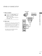
... jacks between TV and external equipment. How to A V or AV IN 1 input, select the A V or A V 1 input source on the remote control. Match the jack colors. (Video = yellow, Audio Left = white, and Audio Right = red) 2. EXTERNAL EQUIPMENT SETUP OTHER A/V SOURCE SETUP 1. I Operate the corresponding external equipment. * AV2: Only 32/37/42/47LH30, 26LU55, 32/37/42/47LF11, 47LF21...
... jacks between TV and external equipment. How to A V or AV IN 1 input, select the A V or A V 1 input source on the remote control. Match the jack colors. (Video = yellow, Audio Left = white, and Audio Right = red) 2. EXTERNAL EQUIPMENT SETUP OTHER A/V SOURCE SETUP 1. I Operate the corresponding external equipment. * AV2: Only 32/37/42/47LH30, 26LU55, 32/37/42/47LF11, 47LF21...
Owner's Manual (English)
Page 41
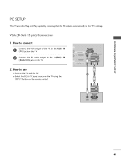
... and Play capability, meaning that the PC adjusts automatically to the AUDIO IN (RGB/DVI) jack on the TV. 2. I Turn on the PC and the TV. R 2 R O 1 RGB IN (PC) AUDIO IN (RGB/DVI) OPTICAL DIGITAL AUDIO OUT RS-232C IN ACNATBELNENIAN/ /DVI IN (CONTROL&SERVICE) 2 1 AUDIO RGB OUTPUT 41 How to connect 1 Connect the VGA output of...
... and Play capability, meaning that the PC adjusts automatically to the AUDIO IN (RGB/DVI) jack on the TV. 2. I Turn on the PC and the TV. R 2 R O 1 RGB IN (PC) AUDIO IN (RGB/DVI) OPTICAL DIGITAL AUDIO OUT RS-232C IN ACNATBELNENIAN/ /DVI IN (CONTROL&SERVICE) 2 1 AUDIO RGB OUTPUT 41 How to connect 1 Connect the VGA output of...

Owner's Manual (English)
Page 42
... on the PC and the TV. AV IN VIDEO AUDIO L(MONO) R 2 DEO L R AUDIO 1 OMPONENT IN RGB IN (PC) AUDIO IN (RGB/DVI) OPTI AU RS-232C IN ACNA /DVI IN (CONTROL&SERVICE) 1 2 DVI OUTPUT AUDIO 42 I N or HDMI/DVI IN 1/2* jack on the TV. 2 Connect the PC audio output to the HDMI/DVI ...I Select the HDMI or HDMI1 / 2* input source on the TV using the INPUT button on the TV. 2. NOTE G Check HDMI cable over version 1.3. How ...
... on the PC and the TV. AV IN VIDEO AUDIO L(MONO) R 2 DEO L R AUDIO 1 OMPONENT IN RGB IN (PC) AUDIO IN (RGB/DVI) OPTI AU RS-232C IN ACNA /DVI IN (CONTROL&SERVICE) 1 2 DVI OUTPUT AUDIO 42 I N or HDMI/DVI IN 1/2* jack on the TV. 2 Connect the PC audio output to the HDMI/DVI ...I Select the HDMI or HDMI1 / 2* input source on the TV using the INPUT button on the TV. 2. NOTE G Check HDMI cable over version 1.3. How ...
Owner's Manual (English)
Page 116
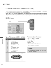
...RS-232C on this unit is intended to be used with programming software or to control the TV's functions externally. APPENDIX 6 9 116 D-Sub 9-Pin Male No. APPENDIX EXTERNAL CONTROL THROUGH... RS-232C The RS-232C port allows you connect the RS-232C input jack to an external control device (such as a computer or an A/V control system) to test ...reverse) cable. ! RS-232C Setup i.e) AV IN EO AUDIO L(MONO) R 2 L R AUDIO 1 ENT IN RGB IN (PC) AUDIO IN (RGB/DVI) OPTICAL DIGITAL AUDIO OUT RS-232C IN ACNATBELNENIAN/ /DVI IN (CONTROL&SERVICE) ...
...RS-232C on this unit is intended to be used with programming software or to control the TV's functions externally. APPENDIX 6 9 116 D-Sub 9-Pin Male No. APPENDIX EXTERNAL CONTROL THROUGH... RS-232C The RS-232C port allows you connect the RS-232C input jack to an external control device (such as a computer or an A/V control system) to test ...reverse) cable. ! RS-232C Setup i.e) AV IN EO AUDIO L(MONO) R 2 L R AUDIO 1 ENT IN RGB IN (PC) AUDIO IN (RGB/DVI) OPTICAL DIGITAL AUDIO OUT RS-232C IN ACNATBELNENIAN/ /DVI IN (CONTROL&SERVICE) ...


