
Owners Manual
Page 1
LCD TV PLASMA TV OWNER'S MANUAL LCD TV MODELS PLASMA TV MODEL 32LC5DC 32LC50C 42PX8DC 32LC5DCS 32LC50CS 42PG65C 32LC5DCB 32LC50CB 42PG60C 37LC5DC 32LX50C 37LC5DCB 32LX50CS 37LC5DC1 37LC50C 42LC5DC 37LC50CB 32LX5DC 42LB50C 32LX5DCS 42LC50C 42LB5DC Please read this information to your set . www.lgcommercial.com Record model number and serial number of the set . See the label attached on the back cover and quote this manual carefully before operating your dealer when you require service. Retain it for future reference.
LCD TV PLASMA TV OWNER'S MANUAL LCD TV MODELS PLASMA TV MODEL 32LC5DC 32LC50C 42PX8DC 32LC5DCS 32LC50CS 42PG65C 32LC5DCB 32LC50CB 42PG60C 37LC5DC 32LX50C 37LC5DCB 32LX50CS 37LC5DC1 37LC50C 42LC5DC 37LC50CB 32LX5DC 42LB50C 32LX5DCS 42LC50C 42LB5DC Please read this information to your set . www.lgcommercial.com Record model number and serial number of the set . See the label attached on the back cover and quote this manual carefully before operating your dealer when you require service. Retain it for future reference.

Owners Manual
Page 3
...Electric Code (U.S.A.). Reorient or relocate the receiving antenna. - NO USER SERVICEABLE PARTS INSIDE. NOTE TO CABLE/TV INSTALLER This reminder is intended to alert the user to correct the interference by one or more of important...frequency energy and, if not installed and used in a particular installation. Consult the dealer or an experienced radio/TV technician for a Class B digital device, pursuant to Part 15 of electric shock to operate this product in ...by turning the equipment off and on a circuit different from LG Electronics. CAUTION Do not attempt to rain or moisture.
...Electric Code (U.S.A.). Reorient or relocate the receiving antenna. - NO USER SERVICEABLE PARTS INSIDE. NOTE TO CABLE/TV INSTALLER This reminder is intended to alert the user to correct the interference by one or more of important...frequency energy and, if not installed and used in a particular installation. Consult the dealer or an experienced radio/TV technician for a Class B digital device, pursuant to Part 15 of electric shock to operate this product in ...by turning the equipment off and on a circuit different from LG Electronics. CAUTION Do not attempt to rain or moisture.

Owners Manual
Page 5
...the product, and do not drop onto the screen with an exact replacement part by an authorized servicer. on or over the apparatus (e.g. a TV with wet hands. The plug must be connected to a three-prong grouned AC outlet) If grounding methods are dangerous. Pay particular attention to ...a dedicated circuit; on shelves above the unit). 17 GROUNDING Ensure that appliances be certain. Do not overload wall outlets. Do not touch the TV with a three-prong grounded AC plug must remain readily operable. 19 Keep the product away from physical or mechanical abuse, such as vases, cups...
...the product, and do not drop onto the screen with an exact replacement part by an authorized servicer. on or over the apparatus (e.g. a TV with wet hands. The plug must be connected to a three-prong grouned AC outlet) If grounding methods are dangerous. Pay particular attention to ...a dedicated circuit; on shelves above the unit). 17 GROUNDING Ensure that appliances be certain. Do not overload wall outlets. Do not touch the TV with a three-prong grounded AC plug must remain readily operable. 19 Keep the product away from physical or mechanical abuse, such as vases, cups...
Owners Manual
Page 6
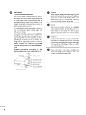
... the mast and supporting structure, grounding of the lead-in excessively dusty places. 24 If you smell smoke or other liquids directly on the TV as a bookcase. Do not press against voltage surges and built-up static charges. Do not cover the product with chemicals such as alcohol,...the product is proper ventilation. Do not install in wire to an antenna discharge unit, size of grounding conductors, location of the TV. 23 Ventilation Install your TV where there is turned off, unplugged and all cables have been removed. Section 810 of overhead power lines or other materials (e.g.) ...
... the mast and supporting structure, grounding of the lead-in excessively dusty places. 24 If you smell smoke or other liquids directly on the TV as a bookcase. Do not press against voltage surges and built-up static charges. Do not cover the product with chemicals such as alcohol,...the product is proper ventilation. Do not install in wire to an antenna discharge unit, size of grounding conductors, location of the TV. 23 Ventilation Install your TV where there is turned off, unplugged and all cables have been removed. Section 810 of overhead power lines or other materials (e.g.) ...

Owners Manual
Page 7
...21 DVD Setup 24 VCR Setup 26 Other A/V Source Setup 28 Digital Audio Output 28 PC Setup 29 WATCHING TV / CHANNEL CONTROL Remote Control Functions 32 Turning On TV 34 Channel Selection 34 Volume Adjustment 34 On-Screen Menus Selection 35 Channel Setup 36 - Setting up Your ...Password 74 Set Password 75 Lock System 75 Channel Blocking 76 External Input Blocking 76 Movie & TV Rating 77 - Add / Delete Channel ...
...21 DVD Setup 24 VCR Setup 26 Other A/V Source Setup 28 Digital Audio Output 28 PC Setup 29 WATCHING TV / CHANNEL CONTROL Remote Control Functions 32 Turning On TV 34 Channel Selection 34 Volume Adjustment 34 On-Screen Menus Selection 35 Channel Setup 36 - Setting up Your ...Password 74 Set Password 75 Lock System 75 Channel Blocking 76 External Input Blocking 76 Movie & TV Rating 77 - Add / Delete Channel ...

Owners Manual
Page 8
...15 pin cable) with the polishing cloth for the product exteri- PREPARATION ACCESSORIES Ensure that excessive pressure for all models. LCD TV PLASMA TV Owner's Manual http://www.lgusa.com www.lg.ca Copyright© 2007 LGE, All Rights Reserved. INPUT MULTI POWER TMVODE EXIT CC EZ PIP PIC EZ PIP CH ...SOUND TV RATSIOTB DVD - This is normal, there is turned on the screen, appearing as tiny red, green, or blue spots. Avoid touching the LCD screen or ...
...15 pin cable) with the polishing cloth for the product exteri- PREPARATION ACCESSORIES Ensure that excessive pressure for all models. LCD TV PLASMA TV Owner's Manual http://www.lgusa.com www.lg.ca Copyright© 2007 LGE, All Rights Reserved. INPUT MULTI POWER TMVODE EXIT CC EZ PIP PIC EZ PIP CH ...SOUND TV RATSIOTB DVD - This is normal, there is turned on the screen, appearing as tiny red, green, or blue spots. Avoid touching the LCD screen or ...

Owners Manual
Page 9
PREPARATION LCD TV model only Option Extras Protective Bracket and Bolt for Power Cord (This feature is not available for all models.) (Refer to P.13) D-sub 15 pin Cable Only 32/37/42LC5DC*, 32/37/42LC50C*, 42LB5DC, 42LB50C models Cable Management (Refer to p.13) Cable Holder (Refer to p.13) ... for fixing the Cable Holder (Refer to p.13) 4-Bolts for stand assembly (Refer to p.18) Only 32/37LC5DC*, 32/37LC50C* models x 2 M4xL22 Torx plus Star head screw (Refer to p.8) Plasma TV models only 75 ohm Round Cable D-sub 15 Pin Cable Only 42PG60C, 42PG65C models Protection cover (Refer to...
PREPARATION LCD TV model only Option Extras Protective Bracket and Bolt for Power Cord (This feature is not available for all models.) (Refer to P.13) D-sub 15 pin Cable Only 32/37/42LC5DC*, 32/37/42LC50C*, 42LB5DC, 42LB50C models Cable Management (Refer to p.13) Cable Holder (Refer to p.13) ... for fixing the Cable Holder (Refer to p.13) 4-Bolts for stand assembly (Refer to p.18) Only 32/37LC5DC*, 32/37LC50C* models x 2 M4xL22 Torx plus Star head screw (Refer to p.8) Plasma TV models only 75 ohm Round Cable D-sub 15 Pin Cable Only 42PG60C, 42PG65C models Protection cover (Refer to...

Owners Manual
Page 10
... a polishing cloth is switched on. Illuminates green when the TV is included with the four screws (provided as parts of the TV). PREPARATION FRONT PANEL CONTROLS ■ Here shown may be somewhat different from your TV. ■ If your product, use it). 32/37/42LC5DC*,32/37/42LC50C*, 42LB5DC, 42LB50C PREPARATION Remote Control Sensor Power...
... a polishing cloth is switched on. Illuminates green when the TV is included with the four screws (provided as parts of the TV). PREPARATION FRONT PANEL CONTROLS ■ Here shown may be somewhat different from your TV. ■ If your product, use it). 32/37/42LC5DC*,32/37/42LC50C*, 42LB5DC, 42LB50C PREPARATION Remote Control Sensor Power...
Owners Manual
Page 11
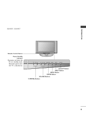
PREPARATION 32LX5DC*, 32LX50C* Remote Control Sensor Power/Standby Indicator Illuminates red when the TV is switched on. CH VOL ENTER MENU INPUT ON/OFF ON/OFF Button INPUT Button MENU Button ENTER Button VOLUME Buttons CHANNEL Buttons 9 Illuminates green when the TV is in standby mode.
PREPARATION 32LX5DC*, 32LX50C* Remote Control Sensor Power/Standby Indicator Illuminates red when the TV is switched on. CH VOL ENTER MENU INPUT ON/OFF ON/OFF Button INPUT Button MENU Button ENTER Button VOLUME Buttons CHANNEL Buttons 9 Illuminates green when the TV is in standby mode.

Owners Manual
Page 12
INPUT MENU ENTER VOL CH Remote Control Sensor Power/Standby Indicator Illuminates red when the TV is switched on . PREPARATION 42PX8DC PREPARATION INPUT ENTER This TV's stand is switched on . POWER Button INPUT Button MENU Button ENTER Button VOLUME Buttons CHANNEL Buttons 42PG60C, 42PG65C Stand (Only 42PG65C model) Remote Control Sensor ... INPUT MENU ENTER VOL CH INPUT MENU ENTER VOL CH INPUT Button MENU Button ENTER Button VOLUME (-,+) Buttons CHANNEL (E, D) Buttons 10 Illuminates green when the TV is in standby mode.
INPUT MENU ENTER VOL CH Remote Control Sensor Power/Standby Indicator Illuminates red when the TV is switched on . PREPARATION 42PX8DC PREPARATION INPUT ENTER This TV's stand is switched on . POWER Button INPUT Button MENU Button ENTER Button VOLUME Buttons CHANNEL Buttons 42PG60C, 42PG65C Stand (Only 42PG65C model) Remote Control Sensor ... INPUT MENU ENTER VOL CH INPUT MENU ENTER VOL CH INPUT Button MENU Button ENTER Button VOLUME (-,+) Buttons CHANNEL (E, D) Buttons 10 Illuminates green when the TV is in standby mode.

Owners Manual
Page 13
PREPARATION VIDEO L/MONO AUDIO R R AUDIO L/MONO VIDEO S-VIDEO R BACK PANEL INFORMATION ■ Here shown may be somewhat different from your TV. 32/37/42LC5DC*,32/37/42LC50C*, 42LB5DC, 42LB50C S-VIDEO 32LX5DC*, 32LX50C* 8 11 ANTE4NN2APINX8DC M.P.I. AV IN 2 11 AV IN 2 S-VIDEO ( ) 8 11 42PG60C, 42PG65C VIDEO L/MONO AUDIO R VIDEO L/MONO AUDIO R R 8 11 AV IN 2 8 AV IN 2 11
PREPARATION VIDEO L/MONO AUDIO R R AUDIO L/MONO VIDEO S-VIDEO R BACK PANEL INFORMATION ■ Here shown may be somewhat different from your TV. 32/37/42LC5DC*,32/37/42LC50C*, 42LB5DC, 42LB50C S-VIDEO 32LX5DC*, 32LX50C* 8 11 ANTE4NN2APINX8DC M.P.I. AV IN 2 11 AV IN 2 S-VIDEO ( ) 8 11 42PG60C, 42PG65C VIDEO L/MONO AUDIO R VIDEO L/MONO AUDIO R R 8 11 AV IN 2 8 AV IN 2 11

Owners Manual
Page 14
...L(MONO) R 9 8 1 HDMI/DVI IN, HDMI IN Connect a HDMI (DVI) connection to either input. 2 DIGITAL AUDIO OUT Connect digital audio from your TV. Caution: Never attempt to operate the TV on DC power. 12 ANTENNA IN Connect over-the air signals to these jacks. 10 RJP INTERFACE 11 Power Cord Socket For... operation with AC power. Note: In standby mode, these jacks. S-VIDEO Connect S-Video out from a PC. This part mainly use picture for the LCD TV models.
...L(MONO) R 9 8 1 HDMI/DVI IN, HDMI IN Connect a HDMI (DVI) connection to either input. 2 DIGITAL AUDIO OUT Connect digital audio from your TV. Caution: Never attempt to operate the TV on DC power. 12 ANTENNA IN Connect over-the air signals to these jacks. 10 RJP INTERFACE 11 Power Cord Socket For... operation with AC power. Note: In standby mode, these jacks. S-VIDEO Connect S-Video out from a PC. This part mainly use picture for the LCD TV models.

Owners Manual
Page 15
... the product. - If the product is not available for all models.) 1 Connect the cables as necessary. It will help prevent the power cable from your TV. (This feature is dropped, you may be injured or the product may be broken. PROTECTIVE BRACKET 2 Install the CABLE HOLDER as shown. 2 Install the CABLE...
... the product. - If the product is not available for all models.) 1 Connect the cables as necessary. It will help prevent the power cable from your TV. (This feature is dropped, you may be injured or the product may be broken. PROTECTIVE BRACKET 2 Install the CABLE HOLDER as shown. 2 Install the CABLE...

Owners Manual
Page 16
Secure the power cable with the PROTECTIVE BRACKET and the screw as necessary. PREPARATION PREPARATION BACK COVER FOR WIRE ARRANGEMENT ■ Here shown may be somewhat different from being removed by accident. 3 Install the CABLE HOLDER as shown. PROTECTIVE BRACKET BOLT CABLE HOLDER 14 To connect an additional equipment, see the EXTERNAL EQUIPMENT SETUP section. It will help prevent the power cable from your TV. (This feature is not available for all models.) 1 To separate the CABLE HOLDER, loosen the bolt installed the set. 2 Connect the cables as shown.
Secure the power cable with the PROTECTIVE BRACKET and the screw as necessary. PREPARATION PREPARATION BACK COVER FOR WIRE ARRANGEMENT ■ Here shown may be somewhat different from being removed by accident. 3 Install the CABLE HOLDER as shown. PROTECTIVE BRACKET BOLT CABLE HOLDER 14 To connect an additional equipment, see the EXTERNAL EQUIPMENT SETUP section. It will help prevent the power cable from your TV. (This feature is not available for all models.) 1 To separate the CABLE HOLDER, loosen the bolt installed the set. 2 Connect the cables as shown.

Owners Manual
Page 17
...How to remove the CABLE MANAGEMENT CLIP G First, press the cable management. NOTE G Do not hold the CABLE MANAGEMENT CLIP when moving the TV. - If your TV has CABLE HOLDER, fix it as shown and bundle the cables. 3 Install the CABLE MANAGEMENT as shown. To connect additional equipment, see the... EXTERNAL EQUIPMENT SETUP section. 2 Install the CABLE MANAGEMENT CLIP as shown. If the TV is dropped, you may be injured or the product may be...
...How to remove the CABLE MANAGEMENT CLIP G First, press the cable management. NOTE G Do not hold the CABLE MANAGEMENT CLIP when moving the TV. - If your TV has CABLE HOLDER, fix it as shown and bundle the cables. 3 Install the CABLE MANAGEMENT as shown. To connect additional equipment, see the... EXTERNAL EQUIPMENT SETUP section. 2 Install the CABLE MANAGEMENT CLIP as shown. If the TV is dropped, you may be injured or the product may be...

Owners Manual
Page 18
...176; (37LC5DC1, 42LC5DC, 42LC50C, 42PX8DC, 42LB5DC, 42LB50C, 42PG60C, 42PG65C models) 90° (32LX5DC/S, 32LX50C/S, 32LC5DC/S, 32LC50C/S, 37LC5DC, 37LC50C models) The TV can be conveniently swivelled on its stand 20°or 90° to the left or right to tie the rope so it becomes horizontal... between the wall and the product. We recommend that is not available for all models. Caution: Please make sure that the TV be pulled in a forward direction, potentially causing injury or damaging the product. Ensure the eye-bolts or brackets are tightened securely. ■...
...176; (37LC5DC1, 42LC5DC, 42LC50C, 42PX8DC, 42LB5DC, 42LB50C, 42PG60C, 42PG65C models) 90° (32LX5DC/S, 32LX50C/S, 32LC5DC/S, 32LC50C/S, 37LC5DC, 37LC50C models) The TV can be conveniently swivelled on its stand 20°or 90° to the left or right to tie the rope so it becomes horizontal... between the wall and the product. We recommend that is not available for all models. Caution: Please make sure that the TV be pulled in a forward direction, potentially causing injury or damaging the product. Ensure the eye-bolts or brackets are tightened securely. ■...

Owners Manual
Page 19
PREPARATION ATTACHING THE TV TO A DESK The TV must be securely attached to desk so it cannot be attached to the floor/wall per installation instructions.Tipping, shaking, or rocking the machine may cause injury/death. 17 M5 x L (table depth + 8~10 mm) ex) table depth-15mm: Bolts - M5 x 25 32/37/42LC5DC*, 32/37/42LC50C*, 42LB5DC, 42LB50C 32LX5DC*, 32LX50C* 4-Screws Stand Desk 42PX8DC 4-Screws Stand Desk Stand 2-Screws Desk WARNING G This apparatus must be pulled in a forward/backward direction, potentially causing injury or damaging the product. * Screws -
PREPARATION ATTACHING THE TV TO A DESK The TV must be securely attached to desk so it cannot be attached to the floor/wall per installation instructions.Tipping, shaking, or rocking the machine may cause injury/death. 17 M5 x L (table depth + 8~10 mm) ex) table depth-15mm: Bolts - M5 x 25 32/37/42LC5DC*, 32/37/42LC50C*, 42LB5DC, 42LB50C 32LX5DC*, 32LX50C* 4-Screws Stand Desk 42PX8DC 4-Screws Stand Desk Stand 2-Screws Desk WARNING G This apparatus must be pulled in a forward/backward direction, potentially causing injury or damaging the product. * Screws -

Owners Manual
Page 20
...Fix the 4 bolts securely using the holes in the back of the TV. After removing the stand, install the included protection cover over the hole for the stand. PREPARATION PREPARATION STAND INSTALLATION ( 32/37LC5DC*, 32/37LC50C* ) 1 Carefully place the product screen side down on a ...cushioned surface that will protect product and screen from damage. ( 42PG60C. 42PG65C ) 1 Carefully place the TV screen side down on a cushioned surface to...
...Fix the 4 bolts securely using the holes in the back of the TV. After removing the stand, install the included protection cover over the hole for the stand. PREPARATION PREPARATION STAND INSTALLATION ( 32/37LC5DC*, 32/37LC50C* ) 1 Carefully place the product screen side down on a ...cushioned surface that will protect product and screen from damage. ( 42PG60C. 42PG65C ) 1 Carefully place the TV screen side down on a cushioned surface to...

Owners Manual
Page 21
..., allow a clearance of 4inches on the wall mount used. For further information, refer to the VESA Wall Mounting Instruction Guide. A B Product LCD TV PLASMA TV Model 32LC5DC*, 32LC50C*, 32LX5DC*, 32LX50C* 32/37/42LC5DC*, 32/37/42LC50C*, 42LB5DC, 42LB50C 42PG60C, 42PG65C 42PX8DC VESA (A * B) 200 * 100 600 * 400 400 * 400 600 * 400 NOTE G Screw length needed depends...
..., allow a clearance of 4inches on the wall mount used. For further information, refer to the VESA Wall Mounting Instruction Guide. A B Product LCD TV PLASMA TV Model 32LC5DC*, 32LC50C*, 32LX5DC*, 32LX50C* 32/37/42LC5DC*, 32/37/42LC50C*, 42LB5DC, 42LB50C 42PG60C, 42PG65C 42PX8DC VESA (A * B) 200 * 100 600 * 400 400 * 400 600 * 400 NOTE G Screw length needed depends...

Owners Manual
Page 22
... picture quality in a poor signal area, please purchase a signal amplifier and install properly. ■ If the antenna needs to be split for two TV's, install a 2-Way Signal Splitter. ■ If the antenna is not installed properly, contact your dealer for outdoor antenna) Copper Wire Be careful not... to wall jack for assistance. For optimum picture quality, adjust antenna direction if needed. NOTE G The TV will let you know when the analog, cable, and digital channel scans are complete. 20 PREPARATION PREPARATION ANTENNA OR CABLE CONNECTION 1. Cable Cable...
... picture quality in a poor signal area, please purchase a signal amplifier and install properly. ■ If the antenna needs to be split for two TV's, install a 2-Way Signal Splitter. ■ If the antenna is not installed properly, contact your dealer for outdoor antenna) Copper Wire Be careful not... to wall jack for assistance. For optimum picture quality, adjust antenna direction if needed. NOTE G The TV will let you know when the analog, cable, and digital channel scans are complete. 20 PREPARATION PREPARATION ANTENNA OR CABLE CONNECTION 1. Cable Cable...


