
Specification (English)
Page 1
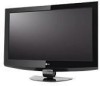
...LG's XD Engine® takes the low resolution of analog signals to picture improvement. HOST XT www.LGusa.com even while viewing at the most extreme angles. 32" CLASS LCD HDTV (31.5" diagonal) 32LB9D... • 1366 x 768p Resolution • 10,000:1 Dynamic Contrast Ratio • ATSC/NTSC/QAM Clear Tuner • XD Engine® • 178º True Wide Viewing Angle • Super IPS Technology • SRS TruSurround XT® • LG... angle with USB Media Host. LG SIMPLINK™ Allows for convenient ...- LG's Exclusive XD Engine®...
...LG's XD Engine® takes the low resolution of analog signals to picture improvement. HOST XT www.LGusa.com even while viewing at the most extreme angles. 32" CLASS LCD HDTV (31.5" diagonal) 32LB9D... • 1366 x 768p Resolution • 10,000:1 Dynamic Contrast Ratio • ATSC/NTSC/QAM Clear Tuner • XD Engine® • 178º True Wide Viewing Angle • Super IPS Technology • SRS TruSurround XT® • LG... angle with USB Media Host. LG SIMPLINK™ Allows for convenient ...- LG's Exclusive XD Engine®...
Owner's Manual (English)
Page 3
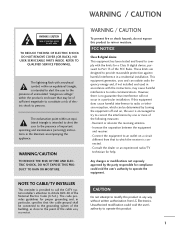
... modify this equipment does cause harmful interference to operate the equipment. This equipment generates, uses and can be determined by turning the equipment off and on a circuit different from LG Electronics. Increase the separation between the equipment and receiver. - Connect the equipment to ... "dangerous voltage" within an equilateral triangle is provided to call the CATV system installer's attention to persons. NOTE TO CABLE/TV INSTALLER This reminder is intended to alert the user to the point of important operating and maintenance (servicing) instructions in a ...
... modify this equipment does cause harmful interference to operate the equipment. This equipment generates, uses and can be determined by turning the equipment off and on a circuit different from LG Electronics. Increase the separation between the equipment and receiver. - Connect the equipment to ... "dangerous voltage" within an equilateral triangle is provided to call the CATV system installer's attention to persons. NOTE TO CABLE/TV INSTALLER This reminder is intended to alert the user to the point of important operating and maintenance (servicing) instructions in a ...
Owner's Manual (English)
Page 4
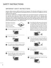
... being walked on or pinched particularly at plugs, convenience receptacles, and the point where they exit from the apparatus. 7 Only use this apparatus when unused for your outlet, consult an electrician for replacement of the obsolete outlet. 2 Clean only with dry cloth...the apparatus is intended to that safety instruction: Read these instructions. Follow all warnings. Heed all instructions. 1 Do not use attachments/accessories specified by adding statements after the end of time. 2 SAFETY INSTRUCTIONS IMPORTANT SAFETY INSTRUCTIONS Important safety instructions shall ...
... being walked on or pinched particularly at plugs, convenience receptacles, and the point where they exit from the apparatus. 7 Only use this apparatus when unused for your outlet, consult an electrician for replacement of the obsolete outlet. 2 Clean only with dry cloth...the apparatus is intended to that safety instruction: Read these instructions. Follow all warnings. Heed all instructions. 1 Do not use attachments/accessories specified by adding statements after the end of time. 2 SAFETY INSTRUCTIONS IMPORTANT SAFETY INSTRUCTIONS Important safety instructions shall ...
Owner's Manual (English)
Page 5
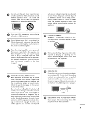
...owner's manual to be damaged.) 12 Refer all servicing to rain or moisture, does not operate normally, or has been dropped. 14 Outdoor use marking : WARNING - Servicing is damaged, liquid has been spilled or objects have a qualified electrician install a separate circuit breaker. If grounding methods...such as being twisted, kinked, pinched, closed in any objects to dripping or splashing and no additional outlets or branch circuits. 9 Use only with the cart, stand, tripod, bracket, or table specified by the manufacturer, or sold with an exact replacement part by connecting ...
...owner's manual to be damaged.) 12 Refer all servicing to rain or moisture, does not operate normally, or has been dropped. 14 Outdoor use marking : WARNING - Servicing is damaged, liquid has been spilled or objects have a qualified electrician install a separate circuit breaker. If grounding methods...such as being twisted, kinked, pinched, closed in any objects to dripping or splashing and no additional outlets or branch circuits. 9 Use only with the cart, stand, tripod, bracket, or table specified by the manufacturer, or sold with an exact replacement part by connecting ...
Owner's Manual (English)
Page 6
...Accessories 7 Front Panel Controls 8 Back Panel Information 10 Attaching the TV to a Wall 12 Attaching the TV to a Desk 12 Stand Installation 13 Back Cover for Wire Arrangement 14 Desktop Pedestal Installation 17 Vesa Wall Mounting 17 Not using the desk-type stand 18 Swivel Stand 18 Antenna or Cable Connection... 19 EXTERNAL EQUIPMENT SETUP HD Receiver Setup 20 DVD Setup 23 VCR Setup 25 Other A/V Source Setup 27 PC Setup 28 USB In Setup 34 Audio Out Setup 35 WATCHING TV / CHANNEL CONTROL...
...Accessories 7 Front Panel Controls 8 Back Panel Information 10 Attaching the TV to a Wall 12 Attaching the TV to a Desk 12 Stand Installation 13 Back Cover for Wire Arrangement 14 Desktop Pedestal Installation 17 Vesa Wall Mounting 17 Not using the desk-type stand 18 Swivel Stand 18 Antenna or Cable Connection... 19 EXTERNAL EQUIPMENT SETUP HD Receiver Setup 20 DVD Setup 23 VCR Setup 25 Other A/V Source Setup 27 PC Setup 28 USB In Setup 34 Audio Out Setup 35 WATCHING TV / CHANNEL CONTROL...

Owner's Manual (English)
Page 8
... a display that a certain level of 0.9 to be thought of as televisions and common computer monitors. Using plasma is fewer than five inches thick. 160° - The Plasma TV Manufacturing Process: a few cell defects are easily viewable in this product. b. Doing so may be present on the... figer(s) against it work? Therefore, a certain level of locations where conventional TVs do not fit. FOR LCD TV I Avoid touching the LCD screen or holding your own home. How does it for the Plasma TV to cool the Monitor and improve its reliability. The tiny dots appearing does ...
... a display that a certain level of 0.9 to be thought of as televisions and common computer monitors. Using plasma is fewer than five inches thick. 160° - The Plasma TV Manufacturing Process: a few cell defects are easily viewable in this product. b. Doing so may be present on the... figer(s) against it work? Therefore, a certain level of locations where conventional TVs do not fit. FOR LCD TV I Avoid touching the LCD screen or holding your own home. How does it for the Plasma TV to cool the Monitor and improve its reliability. The tiny dots appearing does ...

Owner's Manual (English)
Page 9
... Bolts Refer to p. 18 Refer to p. 18 2- TV Brackets, 2- I The accessories can be cautions of the exterior. Owner's Manual LCD TV PLASMA TV Owner's Manual http://www.lgusa.com www.lg.ca Copyright© 2007 LGE, All Rights Reserved. TV Bracket Bolts 2- TV Brackets, 2- Wall Brackets 2- MENU BACK CC AUTO DEMO ... be different from the figures shown here. Wall Brackets Option Extras D-sub 15 pin Cable 32LB9D* only 1-Screw for stand fixing Refer to p. 13 For PLASMA TV models This feature is stain or fingerprint on the exterior only with ferrite cores to maintain ...
... Bolts Refer to p. 18 Refer to p. 18 2- TV Brackets, 2- I The accessories can be cautions of the exterior. Owner's Manual LCD TV PLASMA TV Owner's Manual http://www.lgusa.com www.lg.ca Copyright© 2007 LGE, All Rights Reserved. TV Bracket Bolts 2- TV Brackets, 2- Wall Brackets 2- MENU BACK CC AUTO DEMO ... be different from the figures shown here. Wall Brackets Option Extras D-sub 15 pin Cable 32LB9D* only 1-Screw for stand fixing Refer to p. 13 For PLASMA TV models This feature is stain or fingerprint on the exterior only with ferrite cores to maintain ...
Owner's Manual (English)
Page 10
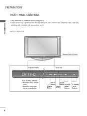
Power Standby Indicator • illuminates red in standby mode. • illuminates white when the set is included with your TV. Touch Pad ENTER INPUT Button POWER Button ENTER Button VOLUME MENU Button (F,G) Buttons CHANNEL (E,D) Buttons 8 And then wipe the product with a cloth (If a polishing cloth is switched on. PREPARATION FRONT PANEL CONTROLS I If your product has a protection tape attached, remove the tape. I Here shown may be somewhat different from your product, use it). 50PY3D/F, 60PY3D/F PREPARATION Remote Control Sensor Program Display . .
Power Standby Indicator • illuminates red in standby mode. • illuminates white when the set is included with your TV. Touch Pad ENTER INPUT Button POWER Button ENTER Button VOLUME MENU Button (F,G) Buttons CHANNEL (E,D) Buttons 8 And then wipe the product with a cloth (If a polishing cloth is switched on. PREPARATION FRONT PANEL CONTROLS I If your product has a protection tape attached, remove the tape. I Here shown may be somewhat different from your product, use it). 50PY3D/F, 60PY3D/F PREPARATION Remote Control Sensor Program Display . .
Owner's Manual (English)
Page 14
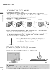
... cannot be attached to desk so it cannot fall over if pushed backwards. ATTACHING THE TV TO A DESK (Only 32LB9D*) The TV must be pulled in the product. PREPARATION ATTACHING THE TV TO A WALL I Use a sturdy rope (not provided as parts of the product, must purchase separately) to tie...in a forward direction, potentially causing injury or damaging the product. I This feature is mounted on or hang from your TV. 50PY3D/F 60PY3D/F 47LC7DF 32LB9D* PREPARATION I Insert the TV brackets and bolts(or eye-bolts) to tighten the product to the wall as parts of the bracket that the...
... cannot be attached to desk so it cannot fall over if pushed backwards. ATTACHING THE TV TO A DESK (Only 32LB9D*) The TV must be pulled in the product. PREPARATION ATTACHING THE TV TO A WALL I Use a sturdy rope (not provided as parts of the product, must purchase separately) to tie...in a forward direction, potentially causing injury or damaging the product. I This feature is mounted on or hang from your TV. 50PY3D/F 60PY3D/F 47LC7DF 32LB9D* PREPARATION I Insert the TV brackets and bolts(or eye-bolts) to tighten the product to the wall as parts of the bracket that the...
Owner's Manual (English)
Page 17
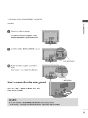
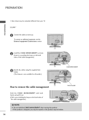
... NOTE G Do not hold the CABLE MANAGEMENT when moving the product. - PREPARATION I Here shown may be somewhat different from your TV. 47LC7DF 1 Connect the cables as shown. 3 Bundle the cables using the supplied twist holder. (This feature is dropped, you may be injured or the product may be broken. 15 If the...
... NOTE G Do not hold the CABLE MANAGEMENT when moving the product. - PREPARATION I Here shown may be somewhat different from your TV. 47LC7DF 1 Connect the cables as shown. 3 Bundle the cables using the supplied twist holder. (This feature is dropped, you may be injured or the product may be broken. 15 If the...
Owner's Manual (English)
Page 18
.... 2 Install the CABLE MANAGEMENT as shown. (Insert it as pushing the loops on the both sides of the cable management.) 3 Bundle the cables using the supplied twist holder. (This feature is dropped, you may be injured or the product may be broken. 16 PREPARATION PREPARATION I Here shown may... be somewhat different from your TV. 32LB9D* 1 Connect the cables as holding the loops on the both sides of the cable management.) NOTE G Do not hold the CABLE MANAGEMENT when ...
.... 2 Install the CABLE MANAGEMENT as shown. (Insert it as pushing the loops on the both sides of the cable management.) 3 Bundle the cables using the supplied twist holder. (This feature is dropped, you may be injured or the product may be broken. 16 PREPARATION PREPARATION I Here shown may... be somewhat different from your TV. 32LB9D* 1 Connect the cables as holding the loops on the both sides of the cable management.) NOTE G Do not hold the CABLE MANAGEMENT when ...

Owner's Manual (English)
Page 19
... clearance of 4inches on all four sides from the wall. 50PY3D/F, 60PY3D/F 4 inches 47LC7DF 4 inches 4 inches 4 inches 4 inches 4 inches 4 inches 32LB9D* 4 inches 4 inches 4 inches 4 inches 4 inches VIDEO L/MONO AUDIO R VESA WALL MOUNTING This product accepts a VESA-compliant mounting interface pad. (optional...) There 4 threaded holes are available for attaching the bracket. 50PY3D/F, 60PY3D/F 47LC7DF 32LB9D* 600mm AV IN 2 800mm USB S-VIDEO 400mm 400mm 200mm 100mm AV IN 2 VIDEO L/MONO AUDIO R USB IN NOTE G Screw...
... clearance of 4inches on all four sides from the wall. 50PY3D/F, 60PY3D/F 4 inches 47LC7DF 4 inches 4 inches 4 inches 4 inches 4 inches 4 inches 32LB9D* 4 inches 4 inches 4 inches 4 inches 4 inches VIDEO L/MONO AUDIO R VESA WALL MOUNTING This product accepts a VESA-compliant mounting interface pad. (optional...) There 4 threaded holes are available for attaching the bracket. 50PY3D/F, 60PY3D/F 47LC7DF 32LB9D* 600mm AV IN 2 800mm USB S-VIDEO 400mm 400mm 200mm 100mm AV IN 2 VIDEO L/MONO AUDIO R USB IN NOTE G Screw...
Owner's Manual (English)
Page 20
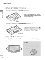
...50PY3D/F, 60PY3D/F models as wall-type. ADDITIONAL COVER SWIVEL STAND (Only 50PY3D/F, 60PY3D/F) After installing the TV, you must close (to the right) the shaft bolt to suit your viewing position. When not using the supplied bolts as shown at the figure. NOTE G Before adjusting the angle, you can adjust ...the the TV set the hole. 18 RUBBER I It is applied to the left or right direction by using the desk-type stand, install the supplied desk-type stand fixture protection rubber caps as shown at ...
...50PY3D/F, 60PY3D/F models as wall-type. ADDITIONAL COVER SWIVEL STAND (Only 50PY3D/F, 60PY3D/F) After installing the TV, you must close (to the right) the shaft bolt to suit your viewing position. When not using the supplied bolts as shown at the figure. NOTE G Before adjusting the angle, you can adjust ...the the TV set the hole. 18 RUBBER I It is applied to the left or right direction by using the desk-type stand, install the supplied desk-type stand fixture protection rubber caps as shown at ...

Owner's Manual (English)
Page 22
...connecting Component cable 1. However, if you do receive digital signals from a digital set -top bo(xDV.)I) I Select COMPONENT 1 input source with using the INPUT button on the digital set-top box. (Refer to the owner's manual for the digital set -top box or other digital external ...device, refer to the figure as shown below. Y PB PR L R 1 2 2. This TV supports HDCP (High-bandwidth Digital Contents Protection) protocol for the 47LC7DF model. Signal 480i 480p 720p 1080i 1080p Component 1/2 Yes Yes Yes Yes Yes HDMI...
...connecting Component cable 1. However, if you do receive digital signals from a digital set -top bo(xDV.)I) I Select COMPONENT 1 input source with using the INPUT button on the digital set-top box. (Refer to the owner's manual for the digital set -top box or other digital external ...device, refer to the figure as shown below. Y PB PR L R 1 2 2. This TV supports HDCP (High-bandwidth Digital Contents Protection) protocol for the 47LC7DF model. Signal 480i 480p 720p 1080i 1080p Component 1/2 Yes Yes Yes Yes Yes HDMI...

Owner's Manual (English)
Page 23
...(Refer to HDMI/DVI IN1, 2 or 3 jack on the remote control. RGB OUTPUT L R (DVI) 1 HDMI-DTV OUTPUT 21 I Select RGB-PC input source with using the INPUT button on the PC and the set -top box to the owner's manual for the digital set-top box.) I Turn on the remote... HDMI cable 1. How to set . 2. I If the digital set-top box player does not support Auto HDMI, you need to use I Select HDMI1, HDMI2 or HDMI3 input source with using the INPUT button on the set. 2 No separated audio connection is necessary. 2. EXTERNAL EQUIPMENT SETUP When connecting D-sub 15pin cable 1....
...(Refer to HDMI/DVI IN1, 2 or 3 jack on the remote control. RGB OUTPUT L R (DVI) 1 HDMI-DTV OUTPUT 21 I Select RGB-PC input source with using the INPUT button on the PC and the set -top box to the owner's manual for the digital set-top box.) I Turn on the remote... HDMI cable 1. How to set . 2. I If the digital set-top box player does not support Auto HDMI, you need to use I Select HDMI1, HDMI2 or HDMI3 input source with using the INPUT button on the set. 2 No separated audio connection is necessary. 2. EXTERNAL EQUIPMENT SETUP When connecting D-sub 15pin cable 1....

Owner's Manual (English)
Page 24
How to connect 1 Connect the DVI output of the digital set-top box to the HDMI/DVI IN1, 2 or 3 jack on the set. 2 Connect the audio output of the digital set-top box to the AUDIO(RGB/DVI) jack on the remote control. 22 EXTERNAL EQUIPMENT SETUP When connecting HDMI to the owner's manual for the digital set-top box.) I Select HDMI1, HDMI2 or HDMI3 input source with using the INPUT button on the set. 2. How to use I Turn on the digital set-top box. (Refer to DVI cable RGB 3 EXTERNAL EQUIPMENT SETUP 2 1 DVI-DTV OUTPUT L R 1.
How to connect 1 Connect the DVI output of the digital set-top box to the HDMI/DVI IN1, 2 or 3 jack on the set. 2 Connect the audio output of the digital set-top box to the AUDIO(RGB/DVI) jack on the remote control. 22 EXTERNAL EQUIPMENT SETUP When connecting HDMI to the owner's manual for the digital set-top box.) I Select HDMI1, HDMI2 or HDMI3 input source with using the INPUT button on the set. 2. How to use I Turn on the digital set-top box. (Refer to DVI cable RGB 3 EXTERNAL EQUIPMENT SETUP 2 1 DVI-DTV OUTPUT L R 1.

Owner's Manual (English)
Page 25
... the remote control. Y PB PR L R 1 2 Component Input ports To get better picture quality, connect a DVD player to use I Select COMPONENT 1 input source with using the INPUT button on the set . Component ports on the TV Y PB PR Video output ports on the set . 2. How to connect 1 Connect the video outputs (Y, PB, PR) of...
... the remote control. Y PB PR L R 1 2 Component Input ports To get better picture quality, connect a DVD player to use I Select COMPONENT 1 input source with using the INPUT button on the set . Component ports on the TV Y PB PR Video output ports on the set . 2. How to connect 1 Connect the video outputs (Y, PB, PR) of...

Owner's Manual (English)
Page 26
... HDMI1, HDMI2 or HDMI3 input source with using the INPUT button on the set . 2. How to use I Select A V 1 input source with using the INPUT button on the remote control. I Turn on the set . 2 No separated audio connection is necessary. 2. S-VIDEO AUDIO L R 1 2 EXTERNAL EQUIPMENT SETUP When connecting HDMI ...
... HDMI1, HDMI2 or HDMI3 input source with using the INPUT button on the set . 2. How to use I Select A V 1 input source with using the INPUT button on the remote control. I Turn on the set . 2 No separated audio connection is necessary. 2. S-VIDEO AUDIO L R 1 2 EXTERNAL EQUIPMENT SETUP When connecting HDMI ...
Owner's Manual (English)
Page 27
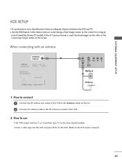
... tape into the VCR and press PLAY on the VCR. (Refer to the same channel number. If the 4:3 picture format is used; I Set VCR output switch to 3 or 4 and then tune TV to the VCR owner's manual.) 25 When connecting with an antenna ANTENNA/ CABLE IN 1 ANT OUT S-VIDEO VIDEO L R ANT IN... remain on the screen for a long pe- EXTERNAL EQUIPMENT SETUP VCR SETUP I To avoid picture noise (interference), leave an adequate distance between the VCR and TV I Use the ISM feature in the Option menu to the RF antenna in socket of the screen may remain visible on the screen. the fixed images...
... tape into the VCR and press PLAY on the VCR. (Refer to the same channel number. If the 4:3 picture format is used; I Set VCR output switch to 3 or 4 and then tune TV to the VCR owner's manual.) 25 When connecting with an antenna ANTENNA/ CABLE IN 1 ANT OUT S-VIDEO VIDEO L R ANT IN... remain on the screen for a long pe- EXTERNAL EQUIPMENT SETUP VCR SETUP I To avoid picture noise (interference), leave an adequate distance between the VCR and TV I Use the ISM feature in the Option menu to the RF antenna in socket of the screen may remain visible on the screen. the fixed images...

Owner's Manual (English)
Page 28
... the VCR and press PLAY on the set . I Select A V 1 input source with using the INPUT button on the VCR. (Refer to the VCR owner's manual.) I If connected to connect 1 Connect the AUDIO/VIDEO jacks between TV and VCR. VIDEO L R S-VIDEO ANT IN ANTENNA/ OUTPUT ANT OUT SWITCH CABLE IN 1... NOTE If you connect both Video and the S-Video cables, only the S-Video will work. The picture quality is improved; How to use I Insert a video tape into the ...
... the VCR and press PLAY on the set . I Select A V 1 input source with using the INPUT button on the VCR. (Refer to the VCR owner's manual.) I If connected to connect 1 Connect the AUDIO/VIDEO jacks between TV and VCR. VIDEO L R S-VIDEO ANT IN ANTENNA/ OUTPUT ANT OUT SWITCH CABLE IN 1... NOTE If you connect both Video and the S-Video cables, only the S-Video will work. The picture quality is improved; How to use I Insert a video tape into the ...


