
Owners Manual
Page 5
Contents 2 Warning 3~4 Safety instructions 7 Accessories / Optional Extras 8 Controls 9 Connection Options 10~1i Remote Control Key Function 12 13 14 15 16~ ! 7 18~ ! 9 20-21 22 22 23 24--26 Attaching the TV to a wall Desktop Pedestal Installation Basic ...
Contents 2 Warning 3~4 Safety instructions 7 Accessories / Optional Extras 8 Controls 9 Connection Options 10~1i Remote Control Key Function 12 13 14 15 16~ ! 7 18~ ! 9 20-21 22 22 23 24--26 Attaching the TV to a wall Desktop Pedestal Installation Basic ...
Owners Manual
Page 6
Contents 41 41 42 42 43 44 45 46 47~48 Manual Clock Setup Auto Clock Setup On!Off Timer Setup Sleep Timer Auto Off Aspect Ratio Control Caption!Text Caption Option Parental Lock Setup 49~53 54~55 56 57~58 59~60 6i 62 External Control Device Setup IR Codes Programming the Remote Programming Codes Troubleshooting Checklist Maintenance Product Specifications 6
Contents 41 41 42 42 43 44 45 46 47~48 Manual Clock Setup Auto Clock Setup On!Off Timer Setup Sleep Timer Auto Off Aspect Ratio Control Caption!Text Caption Option Parental Lock Setup 49~53 54~55 56 57~58 59~60 6i 62 External Control Device Setup IR Codes Programming the Remote Programming Codes Troubleshooting Checklist Maintenance Product Specifications 6
Owners Manual
Page 7
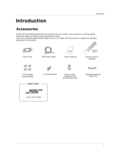
Power Cord 75_ Round Cable Owners Manual Remote Control / Batteries 2oTV brackets 2-Wall brackets 2-TV Bracket BoiLs Option Extras Twister Holder Arrange the wires with your product, if any accessory is missing, please contact the dealer from where you purchased the product. int n Introduction Ensure that the following a_essories are included with the twister holden Cable Management (Refer p.14) D-sub 15 pin Cabte 7 User must use shield signat interface cable (D*sub 15 pin cable) with ferrite cores to maintain the standard compliance for the 3roduct.
Power Cord 75_ Round Cable Owners Manual Remote Control / Batteries 2oTV brackets 2-Wall brackets 2-TV Bracket BoiLs Option Extras Twister Holder Arrange the wires with your product, if any accessory is missing, please contact the dealer from where you purchased the product. int n Introduction Ensure that the following a_essories are included with the twister holden Cable Management (Refer p.14) D-sub 15 pin Cabte 7 User must use shield signat interface cable (D*sub 15 pin cable) with ferrite cores to maintain the standard compliance for the 3roduct.

Owners Manual
Page 8
Introduction - CHANNEL (A, T) Buttons -- VOLUME (_i,!_) Buttons -- This is switched on. This picture shown below may be somewhat different from your TV, Remote Control Sensor Power/Standby Indicator t illuminates red in standby mode. • illuminates green when _e set is a simplified representation of front panel - ENTER Button MENU Button INPUT Button Oil (Power) Button 8
Introduction - CHANNEL (A, T) Buttons -- VOLUME (_i,!_) Buttons -- This is switched on. This picture shown below may be somewhat different from your TV, Remote Control Sensor Power/Standby Indicator t illuminates red in standby mode. • illuminates green when _e set is a simplified representation of front panel - ENTER Button MENU Button INPUT Button Oil (Power) Button 8

Owners Manual
Page 9
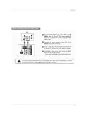
... a PC to operate the TV on a PC, @ Power Cord Socket For operation with AC power, Caution: Never attempt to the appro° pnate input port. @ Remote Control Port Connect your TV. video/audio device to these Connect a second TV or monitor. @AV (Audio/Video) IN 1 Connect audio/video output from an... device. @COMPONENT IN Connect a component jacks. S-VIDEO Input Provides better picture quality than the video, input, VIDEO Input Connects the video signai from your wired remote controL.
... a PC to operate the TV on a PC, @ Power Cord Socket For operation with AC power, Caution: Never attempt to the appro° pnate input port. @ Remote Control Port Connect your TV. video/audio device to these Connect a second TV or monitor. @AV (Audio/Video) IN 1 Connect audio/video output from an... device. @COMPONENT IN Connect a component jacks. S-VIDEO Input Provides better picture quality than the video, input, VIDEO Input Connects the video signai from your wired remote controL.

Owners Manual
Page 10
... onoscreen menus and adjust the system set- (Up/Down/Left Right) tings to the default settings brightness mode source. e it turns to you r preference. Introduction Remote Control Key Functions TV INPUT In AV 1-2, Component 1-2, RGB-PC, HDMI1/DVI or HDMt2 input sources, screen returns to the last channel viewed.
... onoscreen menus and adjust the system set- (Up/Down/Left Right) tings to the default settings brightness mode source. e it turns to you r preference. Introduction Remote Control Key Functions TV INPUT In AV 1-2, Component 1-2, RGB-PC, HDMI1/DVI or HDMt2 input sources, screen returns to the last channel viewed.

Owners Manual
Page 11
...buttons EXiT CC MENU SAP TIMER Ctear all on the viewing environment.(red) _ p.33 Setect the appropriate type of sound for the remote to TV viewing from any menu. Select the amount of the screen (blue) VCRiDVD Control video cassette recorders or DVD players. ...COMP2 Directly, select Componen_ input. COMP1 Directly; RGB-PC Directly; Introduction T% DVD, VCR Selects the remote operating mode: TV, VCR, DVD. Select other operating modes, for type of program.(green) _ p.38 Adjust the screen position, size, and...
...buttons EXiT CC MENU SAP TIMER Ctear all on the viewing environment.(red) _ p.33 Setect the appropriate type of sound for the remote to TV viewing from any menu. Select the amount of the screen (blue) VCRiDVD Control video cassette recorders or DVD players. ...COMP2 Directly, select Componen_ input. COMP1 Directly; RGB-PC Directly; Introduction T% DVD, VCR Selects the remote operating mode: TV, VCR, DVD. Select other operating modes, for type of program.(green) _ p.38 Adjust the screen position, size, and...

Owners Manual
Page 16
... button on the screen. Installation - If the 4:3 picture format is used; the fixed images on the sides of the screen may remain visible on the remote controL. o If connected to the VCR owner's manuaL; Audio LeR = white, and Audio Right = red; Insert a video Lape into the VCR and press PLAY on...
... button on the screen. Installation - If the 4:3 picture format is used; the fixed images on the sides of the screen may remain visible on the remote controL. o If connected to the VCR owner's manuaL; Audio LeR = white, and Audio Right = red; Insert a video Lape into the VCR and press PLAY on...
Owners Manual
Page 17
... button on the set . The picture quality is improved; lnsL_flation VCFI O Connect the S-VIDEO output of the VCR to the AUDIO input jacks on the remote control o If connected to AV IN2 select AV2 input source. compared to normal composite (RCA cable) input, Connect the audio outputs of the VCR to...
... button on the set . The picture quality is improved; lnsL_flation VCFI O Connect the S-VIDEO output of the VCR to the AUDIO input jacks on the remote control o If connected to AV IN2 select AV2 input source. compared to normal composite (RCA cable) input, Connect the audio outputs of the VCR to...

Owners Manual
Page 18
If connected to the DVD player's manua_ for operating instructions Turn on the set . Select AM1 input source with using the INPUT button o_ the remote control. - Refer to AM IN2, select A'_ 2 input source. Installation DVD O Connect the S-VIDE© output of the DVD to the AUDIO input jacks on the set . O Connect the audio outputs of the DVD to the S-VIDEO input on the DVD p ayer, _nsert a DVD.
If connected to the DVD player's manua_ for operating instructions Turn on the set . Select AM1 input source with using the INPUT button o_ the remote control. - Refer to AM IN2, select A'_ 2 input source. Installation DVD O Connect the S-VIDE© output of the DVD to the AUDIO input jacks on the set . O Connect the audio outputs of the DVD to the S-VIDEO input on the DVD p ayer, _nsert a DVD.
Owners Manual
Page 19
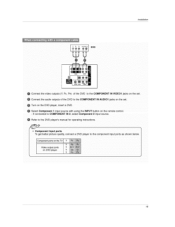
... IN VIDEO1 jacks on the set O Turn on the DVD player, m_ert a DVD Select Corn portent 1 input source with using the INPUT button on the remote control -
... IN VIDEO1 jacks on the set O Turn on the DVD player, m_ert a DVD Select Corn portent 1 input source with using the INPUT button on the remote control -
Owners Manual
Page 20
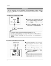
... 2 jack on the set ,top box,) 20 priately. Installation This TV can receive the video and audio signal simultaneously using the INPUT button on the remote control.
... 2 jack on the set ,top box,) 20 priately. Installation This TV can receive the video and audio signal simultaneously using the INPUT button on the remote control.
Owners Manual
Page 21
... best picture quality, adjust the output resolution of the set-top box to the AUDIO IN (RGB!DVI) jack on the set Turn on the remote control.
... best picture quality, adjust the output resolution of the set-top box to the AUDIO IN (RGB!DVI) jack on the set Turn on the remote control.

Owners Manual
Page 22
Refer to AM IN1 input, select AV1 input source. Q Operate the corresponding external equipment. RGB, HDMtl/DVl connected. Installation Connect the AUDIO!VIDEO jacks between TV and external equipment. and HDMI2 sources are - If connected to external equipment operating guide. The TV has a special signal output capability which allows you to hook up a second TV or monitor. 22 Match the iack co$ors (Video = yellow, Audio Left = white, and Audio Right = red), Select AV2 input source with using the INPUT button on the remote control -
Refer to AM IN1 input, select AV1 input source. Q Operate the corresponding external equipment. RGB, HDMtl/DVl connected. Installation Connect the AUDIO!VIDEO jacks between TV and external equipment. and HDMI2 sources are - If connected to external equipment operating guide. The TV has a special signal output capability which allows you to hook up a second TV or monitor. 22 Match the iack co$ors (Video = yellow, Audio Left = white, and Audio Right = red), Select AV2 input source with using the INPUT button on the remote control -

Owners Manual
Page 24
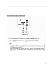
Connect the audio ou_uts of the PC to the AUDIO JN (RGBiDVI) jack on the set . PC Connect the DVI output of the PC to the HDM_ IN 1 (DVI) jack on the remote control 24 Turn on the PC and the se[ Select HDMH/DMI input source with using the INPUT button on the set . Installation This TV provides Plug and Play capability, meaning that the PC adjusts automatically to the TV's settings. !
Connect the audio ou_uts of the PC to the AUDIO JN (RGBiDVI) jack on the set . PC Connect the DVI output of the PC to the HDM_ IN 1 (DVI) jack on the remote control 24 Turn on the PC and the se[ Select HDMH/DMI input source with using the INPUT button on the set . Installation This TV provides Plug and Play capability, meaning that the PC adjusts automatically to the TV's settings. !

Owners Manual
Page 27
...TV on, press the _/I, INPUT, CH A / f button on the TV or press the POWER, TV INPUT, INPUT, CH A / 'V, Number (0 ~ 9) button on the remote control. If you want to adjust the volume 2. You can be shown on °screen menus wNI be shown in the selected language. Press the... buttons to standby mode. 1. First select your desired language From this moment, the TV switches to select your language. press the POWER button on the remote control. 2. The TV reverts to select a channel number. - The menus can cancel this function by using the TV; Press the CH A I f button...
...TV on, press the _/I, INPUT, CH A / f button on the TV or press the POWER, TV INPUT, INPUT, CH A / 'V, Number (0 ~ 9) button on the remote control. If you want to adjust the volume 2. You can be shown on °screen menus wNI be shown in the selected language. Press the... buttons to standby mode. 1. First select your desired language From this moment, the TV switches to select your language. press the POWER button on the remote control. 2. The TV reverts to select a channel number. - The menus can cancel this function by using the TV; Press the CH A I f button...

Owners Manual
Page 30
One is "Custom List" and the other is highlighted and then you can add or delete the channel by toggling each channel on the remote control when a channel is "Favorite List" in the channel list. There are displayed in gray color: Once a channel is highlighted you can add or delete ...
One is "Custom List" and the other is highlighted and then you can add or delete the channel by toggling each channel on the remote control when a channel is "Favorite List" in the channel list. There are displayed in gray color: Once a channel is highlighted you can add or delete ...
Owners Manual
Page 51
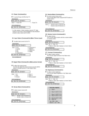
... presents status about each functiom 02. Volume Control (Command2:f) I_ To adjust volume, You can also adjust the screen format using the MUTE button on remote control, Transmission ilk]Jell ][_t ID][ ][D_][Cr] [ Data 0 : Volume mute on (Volume off) 1 : Volume mute off ) Acknowledaement [[all ][Set tD][ ][Datal[Cr] Data 0 ...Elect screen mute on/off, TransmLssion [[kl[d][ l[Set tD][ ][Data][Cr] ] Data 0 : Screen mute off (Picture on) 1 : Screen mute on (Picture off (VoIume on remote control, with the volume buttons Transmission [[k][f][ ][Set IDI[ ][Datal[Cr ] Data Min:O-
... presents status about each functiom 02. Volume Control (Command2:f) I_ To adjust volume, You can also adjust the screen format using the MUTE button on remote control, Transmission ilk]Jell ][_t ID][ ][D_][Cr] [ Data 0 : Volume mute on (Volume off) 1 : Volume mute off ) Acknowledaement [[all ][Set tD][ ][Datal[Cr] Data 0 ...Elect screen mute on/off, TransmLssion [[kl[d][ l[Set tD][ ][Data][Cr] ] Data 0 : Screen mute off (Picture on) 1 : Screen mute on (Picture off (VoIume on remote control, with the volume buttons Transmission [[k][f][ ][Set IDI[ ][Datal[Cr ] Data Min:O-

Owners Manual
Page 52
... • Refer to 'Real data mapping'. Transmission [[k][u][ ][Set ID][ ][Data][Cr] ] Data 0: Medium 1: Cool 2: Warm 3: User Acknowledqement [[u][ ][Set ID][ ][OK][Data][x] ] Remote Control Lock Mode (Command2:m) • To lock the remote control and the front panel controls on [[I [k][i][ l[Set Ig][ l[gatal[Cr] J Data Min:0~Max:64 + Refer to 'Real data mapping'. Sharpness...
... • Refer to 'Real data mapping'. Transmission [[k][u][ ][Set ID][ ][Data][Cr] ] Data 0: Medium 1: Cool 2: Warm 3: User Acknowledqement [[u][ ][Set ID][ ][OK][Data][x] ] Remote Control Lock Mode (Command2:m) • To lock the remote control and the front panel controls on [[I [k][i][ l[Set Ig][ l[gatal[Cr] J Data Min:0~Max:64 + Refer to 'Real data mapping'. Sharpness...

Owners Manual
Page 53
... using physical channel, NTSC cable 'xx' data: don't care major and minor channel number in case digital channel tuning. 3. Key (Command: m c) I_ To send IR remote key code Transmission I[m][c][ ][Set ID][ ][gata][Cr] I Data Key code: Refer to following physical/major/minor Transmission number I[m][a][ ][Set Ig][ ][gata0][ ][gatal][ ][Dala2][ Igata3][ ][Data4I...
... using physical channel, NTSC cable 'xx' data: don't care major and minor channel number in case digital channel tuning. 3. Key (Command: m c) I_ To send IR remote key code Transmission I[m][c][ ][Set ID][ ][gata][Cr] I Data Key code: Refer to following physical/major/minor Transmission number I[m][a][ ][Set Ig][ ][gata0][ ][gatal][ ][Dala2][ Igata3][ ][Data4I...


