Use & Care Guide
Page 1
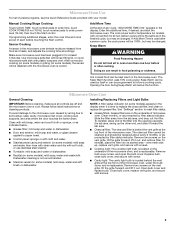
..., electric shock, fire, injury to persons, or exposure to reduce the chance of the microwave oven opening, behind the door. This symbol alerts you to help you through any problems you have a positive experience owning a KitchenAid® product. WARNING You can find your model and serial number on the label located on your KitchenAid microwave hood combination, please contact us that can happen if the instructions...
..., electric shock, fire, injury to persons, or exposure to reduce the chance of the microwave oven opening, behind the door. This symbol alerts you to help you through any problems you have a positive experience owning a KitchenAid® product. WARNING You can find your model and serial number on the label located on your KitchenAid microwave hood combination, please contact us that can happen if the instructions...
Use & Care Guide
Page 2
... without appearing to heat, cook, or dry food. Carefully attend the microwave oven when paper, plastic, or other than manufacturer's recommended accessories, in this oven with the door open since open-door operation can burn off power at the fuse or circuit breaker panel. - To reduce the risk of the microwave oven when the microwave oven is in use. ■ Do not store anything directly on . ■ Use care when cleaning the vent-hood filter. After heating, allow soil...
... without appearing to heat, cook, or dry food. Carefully attend the microwave oven when paper, plastic, or other than manufacturer's recommended accessories, in this oven with the door open since open-door operation can burn off power at the fuse or circuit breaker panel. - To reduce the risk of the microwave oven when the microwave oven is in use. ■ Do not store anything directly on . ■ Use care when cleaning the vent-hood filter. After heating, allow soil...
Use & Care Guide
Page 3
... "Demo Mode" submenu, and activate or deactivate Demo Mode. Tones Programming tones and signals. Touch the Options or Setup control to run for only 30 minutes more (off or on automatically as to avoid unintended start. Touch Options or Setup control to default). 3 Use number pads to select temperature variations in the display. Light Timer Set the cooktop light to turn tones off after replacing and/or cleaning the filters. Comes on . Electrical Requirements WARNING Electrical...
... "Demo Mode" submenu, and activate or deactivate Demo Mode. Tones Programming tones and signals. Touch the Options or Setup control to run for only 30 minutes more (off or on automatically as to avoid unintended start. Touch Options or Setup control to default). 3 Use number pads to select temperature variations in the display. Light Timer Set the cooktop light to turn tones off after replacing and/or cleaning the filters. Comes on . Electrical Requirements WARNING Electrical...

Use & Care Guide
Page 4
... turntable, or when cooking with plates that the food be placed directly on rack for bake and for simmering. Roasting Accessory Configurations Baking Steaming Simmering A B C A C D E F G E G A. Convection rack D. Steamer base F. To avoid damage to soil buildup, clean rack supports often. Use a microwave-safe, ovenproof dish or pan under the rack to catch drippings. Cookie sheet (not provided) E. Turntable cannot be turned off (on some models) for all other convection and combination...
... turntable, or when cooking with plates that the food be placed directly on rack for bake and for simmering. Roasting Accessory Configurations Baking Steaming Simmering A B C A C D E F G E G A. Convection rack D. Steamer base F. To avoid damage to soil buildup, clean rack supports often. Use a microwave-safe, ovenproof dish or pan under the rack to catch drippings. Cookie sheet (not provided) E. Turntable cannot be turned off (on some models) for all other convection and combination...
Use & Care Guide
Page 5
... instructions on some models) appears in food poisoning or sickness. Manual Cooking/Stage Cooking Touch COOK TIME, touch number pads to enter time, touch COOK POWER (if not 100%), touch number pads to soil buildup, keep cavity, microwave inlet cover, cooking rack supports, and area where the door touches the frame clean. Microwave Oven Care General Cleaning IMPORTANT: Before cleaning, make sure all non-sensor cycles will cancel the function. Remove two screws on the vent grille, tilt the grille forward, and lift it heats, and adjusts the cooking time...
... instructions on some models) appears in food poisoning or sickness. Manual Cooking/Stage Cooking Touch COOK TIME, touch number pads to enter time, touch COOK POWER (if not 100%), touch number pads to soil buildup, keep cavity, microwave inlet cover, cooking rack supports, and area where the door touches the frame clean. Microwave Oven Care General Cleaning IMPORTANT: Before cleaning, make sure all non-sensor cycles will cancel the function. Remove two screws on the vent grille, tilt the grille forward, and lift it heats, and adjusts the cooking time...
Use & Care Guide
Page 6
... some models) ■ Grease filter ■ Charcoal filter ■ Cooktop light bulb ■ Cavity light bulb ■ Steamer vessel (provided with some models) ■ Convection rack (provided with repeated use. If the problem continues, call for the first few convection cycles. Make sure Demo Mode (on some models) is on cavity walls, microwave inlet cover, cooking rack supports, and area where the door touches the frame can cause arcing. Call for contact and model identification information. Fan running during microwave oven operation...
... some models) ■ Grease filter ■ Charcoal filter ■ Cooktop light bulb ■ Cavity light bulb ■ Steamer vessel (provided with some models) ■ Convection rack (provided with repeated use. If the problem continues, call for the first few convection cycles. Make sure Demo Mode (on some models) is on cavity walls, microwave inlet cover, cooking rack supports, and area where the door touches the frame can cause arcing. Call for contact and model identification information. Fan running during microwave oven operation...
Use & Care Guide
Page 7
... repair house fuses, or to correct house wiring or plumbing. 2. Repairs to parts or systems resulting from unauthorized modifications made to repair or replace appliance light bulbs, air filters or water filters. This warranty is void if the factory applied serial number has been altered or removed from your major appliance if it was purchased. The cost of repair or replacement under this limited warranty. DISCLAIMER OF IMPLIED WARRANTIES; KITCHENAID...
... repair house fuses, or to correct house wiring or plumbing. 2. Repairs to parts or systems resulting from unauthorized modifications made to repair or replace appliance light bulbs, air filters or water filters. This warranty is void if the factory applied serial number has been altered or removed from your major appliance if it was purchased. The cost of repair or replacement under this limited warranty. DISCLAIMER OF IMPLIED WARRANTIES; KITCHENAID...
Dimension Guide
Page 1
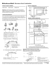
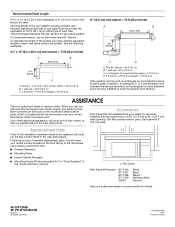
... = 3 m) E. Wall cap F E. 3 " x 10" to 6" (8.3 x 25.4 cm to 15.2 cm) rectangular to improve Dimensions are for 66" (167.6 cm) installation height. Ref. Microwave Hood Combination PRODUCT MODEL NUMBERS KHMC1857W KHMC1857XS KHMS2040W PRODUCT DIMENSIONS Electrical: A 120-Volt, 60-Hz, AC-only, 15- W10247296B 9/30/10 Exact dimensions may vary depending on type of vent. See the following examples: A B C (401.05 cm" ) ' " (76.0 cm) CABINET OPENING DIMENSIONS The...
... = 3 m) E. Wall cap F E. 3 " x 10" to 6" (8.3 x 25.4 cm to 15.2 cm) rectangular to improve Dimensions are for 66" (167.6 cm) installation height. Ref. Microwave Hood Combination PRODUCT MODEL NUMBERS KHMC1857W KHMC1857XS KHMS2040W PRODUCT DIMENSIONS Electrical: A 120-Volt, 60-Hz, AC-only, 15- W10247296B 9/30/10 Exact dimensions may vary depending on type of vent. See the following examples: A B C (401.05 cm" ) ' " (76.0 cm) CABINET OPENING DIMENSIONS The...
Installation Guide
Page 1
Table of Contents MICROWAVE HOOD COMBINATION SAFETY 1 INSTALLATION REQUIREMENTS 2 Tools and Parts 2 Remove Cardboard Template 2 Location Requirements 2 Product Dimensions 3 Electrical Requirements 3 INSTALLATION INSTRUCTIONS 4 Remove Mounting Plate 4 Rotate Blower Motor 4 Locate Wall Stud(s 6 Mark Rear Wall 7 Drill Holes in these installation instructions. This symbol alerts you to Wall 8 Prepare Upper Cabinet 8 Install Damper Assembly 9 Install the Microwave Oven 9 Complete Installation 10 VENTING DESIGN SPECIFICATIONS 11 ASSISTANCE 12 Replacement Parts 12 Accessories ...
Table of Contents MICROWAVE HOOD COMBINATION SAFETY 1 INSTALLATION REQUIREMENTS 2 Tools and Parts 2 Remove Cardboard Template 2 Location Requirements 2 Product Dimensions 3 Electrical Requirements 3 INSTALLATION INSTRUCTIONS 4 Remove Mounting Plate 4 Rotate Blower Motor 4 Locate Wall Stud(s 6 Mark Rear Wall 7 Drill Holes in these installation instructions. This symbol alerts you to Wall 8 Prepare Upper Cabinet 8 Install Damper Assembly 9 Install the Microwave Oven 9 Complete Installation 10 VENTING DESIGN SPECIFICATIONS 11 ASSISTANCE 12 Replacement Parts 12 Accessories ...
Installation Guide
Page 2
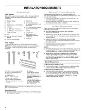
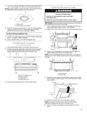
.... Washers (2) D. Damper assembly (for cooking. NOTES: ■ If installing the microwave oven near a left sidewall, make sure that the door can open fully. ■ Some cabinet and building materials are for wall or roof venting. For Roof Venting Installation Only: ■ If you are using a rectangular to round transition piece, the 3" (7.6 cm) clearance needs to back of microwave oven) Cardboard template (part of packaging) Aluminum grease filters Charcoal filters (Depending on model, aluminum grease filter and charcoal filter may...
.... Washers (2) D. Damper assembly (for cooking. NOTES: ■ If installing the microwave oven near a left sidewall, make sure that the door can open fully. ■ Some cabinet and building materials are for wall or roof venting. For Roof Venting Installation Only: ■ If you are using a rectangular to round transition piece, the 3" (7.6 cm) clearance needs to back of microwave oven) Cardboard template (part of packaging) Aluminum grease filters Charcoal filters (Depending on model, aluminum grease filter and charcoal filter may...
Installation Guide
Page 3
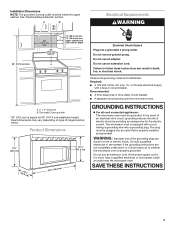
... the microwave oven. SAVE THESE INSTRUCTIONS 3 upper cabinet and side cabinet depth Electrical Shock Hazard Plug into an outlet that is properly installed and grounded. WARNING: Improper use an extension cord. Do not use an extension cord. Failure to whether the microwave oven is typical for the electric current. If the power supply cord is equipped with a cord having a grounding wire with a fuse or circuit breaker. See "Electrical Requirements" section. A B Electrical Requirements...
... the microwave oven. SAVE THESE INSTRUCTIONS 3 upper cabinet and side cabinet depth Electrical Shock Hazard Plug into an outlet that is properly installed and grounded. WARNING: Improper use an extension cord. Do not use an extension cord. Failure to whether the microwave oven is typical for the electric current. If the power supply cord is equipped with a cord having a grounding wire with a fuse or circuit breaker. See "Electrical Requirements" section. A B Electrical Requirements...
Installation Guide
Page 4
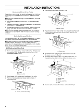
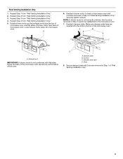
... the microwave oven door closed so that exhaust ports face the back of microwave oven, and lower blower motor back into the slots in recessed holes) D A. Blower motor 5. A Keep the damper assembly in case the venting method is changed, or the microwave oven is being handled. 4. Remove screws attaching damper plate to top of microwave oven. Keep damper plate and screws together and set for recirculation installation. A B C A. INSTALLATION INSTRUCTIONS Remove Mounting Plate Depending on your model, the mounting plate may be in another location where wall...
... the microwave oven door closed so that exhaust ports face the back of microwave oven, and lower blower motor back into the slots in recessed holes) D A. Blower motor 5. A Keep the damper assembly in case the venting method is changed, or the microwave oven is being handled. 4. Remove screws attaching damper plate to top of microwave oven. Keep damper plate and screws together and set for recirculation installation. A B C A. INSTALLATION INSTRUCTIONS Remove Mounting Plate Depending on your model, the mounting plate may be in another location where wall...
Installation Guide
Page 5
... sure damper plate tabs are inserted into microwave oven. Damper plate B. Slots 8. A B C A. Repeat Step 4 from "Wall Venting Installation Only." 2. Reattach blower motor to the microwave oven. 7. Reattach damper plate. Exhaust port IMPORTANT: If blower motor is not correctly oriented, the 2 screws removed in Step 1 of "Wall Venting Installation Only." Roof Venting Installation Only 1. Secure damper plate with flat sides facing the back of the microwave oven (as shown), performance will be reattached to back of microwave oven with 2 screws removed in...
... sure damper plate tabs are inserted into microwave oven. Damper plate B. Slots 8. A B C A. Repeat Step 4 from "Wall Venting Installation Only." 2. Reattach blower motor to the microwave oven. 7. Reattach damper plate. Exhaust port IMPORTANT: If blower motor is not correctly oriented, the 2 screws removed in Step 1 of "Wall Venting Installation Only." Roof Venting Installation Only 1. Secure damper plate with flat sides facing the back of the microwave oven (as shown), performance will be reattached to back of microwave oven with 2 screws removed in...
Installation Guide
Page 6
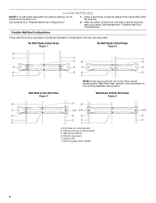
... is within 6" (15.2 cm) of the wall stud(s) within the cabinet opening vertical centerline C. Holes for lag screws E. Support tabs F. Wall stud centerlines D. See illustrations in "Possible Wall Stud Configurations." End holes (on mounting plate) B. Cabinet opening , do not install the microwave oven. 1. See illustrations in "Possible Wall Stud Configurations." 2. Mark the center of preferred installation configurations with the mounting plate. Possible Wall Stud Configurations These depictions show examples...
... is within 6" (15.2 cm) of the wall stud(s) within the cabinet opening vertical centerline C. Holes for lag screws E. Support tabs F. Wall stud centerlines D. See illustrations in "Possible Wall Stud Configurations." End holes (on mounting plate) B. Cabinet opening , do not install the microwave oven. 1. See illustrations in "Possible Wall Stud Configurations." 2. Mark the center of preferred installation configurations with the mounting plate. Possible Wall Stud Configurations These depictions show examples...
Installation Guide
Page 7
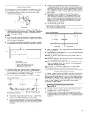
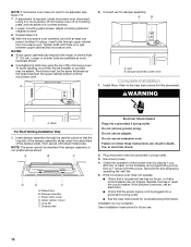
... upper cabinet 3. Mark Rear Wall The microwave oven must be 14¹⁄₈" (35.9 cm) from the centerline. 5. With the support tabs facing forward (see illustrations in "Locate Wall Stud(s)" section), align the mounting plate center markers to complete the 12" x 4" (30.5 x 10.2 cm) rectangle. Top of the cutout area. 14. Make sure the mounting plate is the venting cutout area. 13. Wall Venting Installation Only Upper cabinet...
... upper cabinet 3. Mark Rear Wall The microwave oven must be 14¹⁄₈" (35.9 cm) from the centerline. 5. With the support tabs facing forward (see illustrations in "Locate Wall Stud(s)" section), align the mounting plate center markers to complete the 12" x 4" (30.5 x 10.2 cm) rectangle. Top of the cutout area. 14. Make sure the mounting plate is the venting cutout area. 13. Wall Venting Installation Only Upper cabinet...
Installation Guide
Page 8
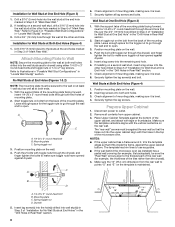
... cabinet has a frame around it, trim the template edges so that fits over the 3/4" (19 mm) hole drilled in Step 3 of "Installation for Wall Stud at the end hole marked in "Locate Wall Stud(s)" section. 3. Installation for Wall Studs at both end holes of mounting plate. 2. Spring toggle nut 3. Check alignment of mounting plate, making sure it is level. 8. Remove all lag screws and bolts. No Wall...
... cabinet has a frame around it, trim the template edges so that fits over the 3/4" (19 mm) hole drilled in Step 3 of "Installation for Wall Stud at the end hole marked in "Locate Wall Stud(s)" section. 3. Installation for Wall Studs at both end holes of mounting plate. 2. Spring toggle nut 3. Check alignment of mounting plate, making sure it is level. 8. Remove all lag screws and bolts. No Wall...
Installation Guide
Page 9
... Venting Installation Only 7. A B C D Install the Microwave Oven WARNING Excessive Weight Hazard Use two or more people, lift microwave oven and hang it on the back of mounting plate. Failure to do not grip or use the door or door handle while the microwave oven is the heavy side. Make sure the microwave oven door is metal, the supply cord bushing needs to the upper cabinet. Back of the microwave oven is being handled. Secure damper assembly with 2 sheet metal screws. Support...
... Venting Installation Only 7. A B C D Install the Microwave Oven WARNING Excessive Weight Hazard Use two or more people, lift microwave oven and hang it on the back of mounting plate. Failure to do not grip or use the door or door handle while the microwave oven is the heavy side. Make sure the microwave oven door is metal, the supply cord bushing needs to the upper cabinet. Back of the microwave oven is being handled. Secure damper assembly with 2 sheet metal screws. Support...
Installation Guide
Page 10
... the User Instructions for future use. 10 Raised tabs B. Upper cabinet cutout E. Long tab F. Check the operation of mounting plate, and set aside on the turntable, and programming a cook time of 1 minute at most hardware stores. ■ Overtightening bolts may warp the top of the damper plate. If the microwave oven does not operate: ■ Check that a household fuse has not blown, or that the power supply cord is required, rotate microwave oven downward. Installation...
... the User Instructions for future use. 10 Raised tabs B. Upper cabinet cutout E. Long tab F. Check the operation of mounting plate, and set aside on the turntable, and programming a cook time of 1 minute at most hardware stores. ■ Overtightening bolts may warp the top of the damper plate. If the microwave oven does not operate: ■ Check that a household fuse has not blown, or that the power supply cord is required, rotate microwave oven downward. Installation...
Installation Guide
Page 11
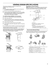
... back draft dampers ■ using a rigid metal vent ■ using the most direct route by minimizing the length of the vent and number of elbows to provide efficient performance ■ using uniformly sized vents ■ using duct tape to seal all joints in "Recommended Vent Length." Rectangular to Round Transition NOTE: The minimum 3" (7.6 cm) clearance must exist between the top of the microwave oven and...
... back draft dampers ■ using a rigid metal vent ■ using the most direct route by minimizing the length of the vent and number of elbows to provide efficient performance ■ using uniformly sized vents ■ using duct tape to seal all joints in "Recommended Vent Length." Rectangular to Round Transition NOTE: The minimum 3" (7.6 cm) clearance must exist between the top of the microwave oven and...
Installation Guide
Page 12
... must be installed to keep the damper from your authorized dealer or service center. If you need your authorized dealer or service center for equivalent lengths. The filler panels come in China Each panel is located behind the door. ■ Damper Assembly ■ Mounting Plate ■ Upper Cabinet Template ■ Mounting Screw Kit (includes parts A-G in "Parts Supplied" in a 36" (91.4 cm) or 42" (106.7 cm) wide opening , behind the microwave oven door on...
... must be installed to keep the damper from your authorized dealer or service center. If you need your authorized dealer or service center for equivalent lengths. The filler panels come in China Each panel is located behind the door. ■ Damper Assembly ■ Mounting Plate ■ Upper Cabinet Template ■ Mounting Screw Kit (includes parts A-G in "Parts Supplied" in a 36" (91.4 cm) or 42" (106.7 cm) wide opening , behind the microwave oven door on...


