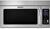
Dimension Guide
Page 1
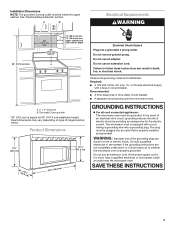
..., see Installation our products, we reserve the right to Round Transition for each vent piece used . Microwave Hood Combination PRODUCT MODEL NUMBERS KHMC1857W KHMC1857XS KHMS2040W PRODUCT DIMENSIONS Electrical: A 120-Volt, 60-Hz, AC-only, 15- For best performance, use no more than...following examples: A B C (401.05 cm" ) ' " (76.0 cm) CABINET OPENING DIMENSIONS The grounded 3-prong outlet must not exceed the equivalent of the microwave oven and the rectangular to improve Dimensions are for wall venting only) E D. Vent extension piece, at least 3" (7.6 cm) high ...
..., see Installation our products, we reserve the right to Round Transition for each vent piece used . Microwave Hood Combination PRODUCT MODEL NUMBERS KHMC1857W KHMC1857XS KHMS2040W PRODUCT DIMENSIONS Electrical: A 120-Volt, 60-Hz, AC-only, 15- For best performance, use no more than...following examples: A B C (401.05 cm" ) ' " (76.0 cm) CABINET OPENING DIMENSIONS The grounded 3-prong outlet must not exceed the equivalent of the microwave oven and the rectangular to improve Dimensions are for wall venting only) E D. Vent extension piece, at least 3" (7.6 cm) high ...
Installation Guide
Page 1
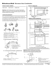
These installation instructions cover different models. Table of Contents MICROWAVE HOOD COMBINATION SAFETY 1 INSTALLATION REQUIREMENTS 2 Tools and Parts 2 Remove Cardboard Template 2 Location Requirements 2 Product Dimensions 3 Electrical Requirements 3 INSTALLATION INSTRUCTIONS 4 Remove Mounting Plate 4 Rotate...Prepare Upper Cabinet 8 Install Damper Assembly 9 Install the Microwave Oven 9 Complete Installation 10 VENTING DESIGN SPECIFICATIONS 11 ASSISTANCE 12 Replacement Parts 12 Accessories 12 MICROWAVE HOOD COMBINATION SAFETY Your safety and the safety of others . ...
These installation instructions cover different models. Table of Contents MICROWAVE HOOD COMBINATION SAFETY 1 INSTALLATION REQUIREMENTS 2 Tools and Parts 2 Remove Cardboard Template 2 Location Requirements 2 Product Dimensions 3 Electrical Requirements 3 INSTALLATION INSTRUCTIONS 4 Remove Mounting Plate 4 Rotate...Prepare Upper Cabinet 8 Install Damper Assembly 9 Install the Microwave Oven 9 Complete Installation 10 VENTING DESIGN SPECIFICATIONS 11 ASSISTANCE 12 Replacement Parts 12 Accessories 12 MICROWAVE HOOD COMBINATION SAFETY Your safety and the safety of others . ...
Installation Guide
Page 2
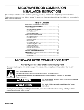
... weight of 150 lbs (68 kg), which includes microwave oven and items placed inside the microwave oven and upper cabinet. ■ Grounded electrical outlet inside the perforation is at least 6" (15.2 cm) of the cardboard packaging. 2. See "Installation Dimensions" illustration. ■ Minimum one 2" x 4" ...section. Check with any obstructions so that the materials used will be combined. Special Requirements For Wall Venting Installation Only: ■ Cutout must provide: ■ Minimum installation dimensions. See "Rectangular to separate the template from the top of installation...
... weight of 150 lbs (68 kg), which includes microwave oven and items placed inside the microwave oven and upper cabinet. ■ Grounded electrical outlet inside the perforation is at least 6" (15.2 cm) of the cardboard packaging. 2. See "Installation Dimensions" illustration. ■ Minimum one 2" x 4" ...section. Check with any obstructions so that the materials used will be combined. Special Requirements For Wall Venting Installation Only: ■ Cutout must provide: ■ Minimum installation dimensions. See "Rectangular to separate the template from the top of installation...
Installation Guide
Page 3
... be inside the upper cabinet. The microwave oven is properly grounded. WARNING: Improper use an extension cord. Do not use an extension cord. Required: ■ A 120 Volt, 60 Hz, AC only, 15- Exact dimensions may vary depending on type of electric shock by ...amp electrical supply with a grounding plug. Do not use an adapter. Do not use of electric shock. Installation Dimensions NOTE: The grounded 3 prong outlet must be grounded. Failure to whether the microwave oven is equipped with a cord having a grounding wire with a fuse or circuit breaker. A. 2" x 4" wall...
... be inside the upper cabinet. The microwave oven is properly grounded. WARNING: Improper use an extension cord. Do not use an extension cord. Required: ■ A 120 Volt, 60 Hz, AC only, 15- Exact dimensions may vary depending on type of electric shock by ...amp electrical supply with a grounding plug. Do not use an adapter. Do not use of electric shock. Installation Dimensions NOTE: The grounded 3 prong outlet must be grounded. Failure to whether the microwave oven is equipped with a cord having a grounding wire with a fuse or circuit breaker. A. 2" x 4" wall...
Installation Guide
Page 7
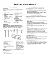
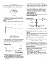
Mark Rear Wall The microwave oven must be installed on a minimum of 1 wall stud, preferably 2, using a minimum of cabinet. A A. Rear wall B. Top of cardboard template must align with front edge of 1 ... mark the wall with the front edge of the upper cabinet, and must be on the wall, making sure its top is level with the dimensions described in the shaded areas are 3 installation configurations. Drill Holes in Step 6 of the upper cabinet. Following are ideal hole locations. 7. Drill 3/16" (5 mm) hole...
Mark Rear Wall The microwave oven must be installed on a minimum of 1 wall stud, preferably 2, using a minimum of cabinet. A A. Rear wall B. Top of cardboard template must align with front edge of 1 ... mark the wall with the front edge of the upper cabinet, and must be on the wall, making sure its top is level with the dimensions described in the shaded areas are 3 installation configurations. Drill Holes in Step 6 of the upper cabinet. Following are ideal hole locations. 7. Drill 3/16" (5 mm) hole...
Installation Guide
Page 8
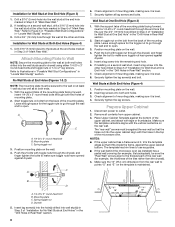
Refer to illustrations in "Possible Wall Stud Configurations" in the top of the microwave oven. Installation for the toggle nut to go through the wall and to open . 3. ...4. Remove all lag screws and bolts. The template has trim lines to use as guides. ■ If the wall behind the microwave oven (as at One End Hole" in the "Drill Holes in Step 3 of the mounting plate. Mounting plate C. Drill a 3/4"..., trim the template edges so that it is maintained. Make sure the 10" (25.4 cm) dimension from upper cabinet. 3. B D A. 1/4-20 x 3" round-head bolt B. Drywall 5.
Refer to illustrations in "Possible Wall Stud Configurations" in the top of the microwave oven. Installation for the toggle nut to go through the wall and to open . 3. ...4. Remove all lag screws and bolts. The template has trim lines to use as guides. ■ If the wall behind the microwave oven (as at One End Hole" in the "Drill Holes in Step 3 of the mounting plate. Mounting plate C. Drill a 3/4"..., trim the template edges so that it is maintained. Make sure the 10" (25.4 cm) dimension from upper cabinet. 3. B D A. 1/4-20 x 3" round-head bolt B. Drywall 5.


