
Instruction Manual
Page 1
...) KRC-108S CASSETTE RECEIVER INSTRUCTION MANUAL AMPLI-TUNER-LECTEUR DE CASSETTE MODE D'EMPLOI RADIO CASETE MANUAL DE INSTRUCCIONES RADIO CASSETE MANUAL DE INSTRUÇÕES Take the time to the model and serial numbers whenever you obtain the best performance from your new cassette-receiver. Familiarity with installation and operation procedures will help you call upon your records Record the serial number, found on the back of the unit...
...) KRC-108S CASSETTE RECEIVER INSTRUCTION MANUAL AMPLI-TUNER-LECTEUR DE CASSETTE MODE D'EMPLOI RADIO CASETE MANUAL DE INSTRUCCIONES RADIO CASSETE MANUAL DE INSTRUÇÕES Take the time to the model and serial numbers whenever you obtain the best performance from your new cassette-receiver. Familiarity with installation and operation procedures will help you call upon your records Record the serial number, found on the back of the unit...

Instruction Manual
Page 2
... Contents Before use Safety precautions 3 General features Power 5 Switching Modes 5 Volume 6 Attenuator 6 Loudness 6 Audio Control Setting 6 ec4/dB (Sound Coordinate 7 Clock display 7 Adjusting Time 7 Tuner features Tuning 8 Station Preset Memory 8 Auto Memory Entry 9 Clean Reception System Circuit (CRSC 9 Cassette player features Playing Cassette Tapes 10 Fast Forwarding and Rewinding Cassette Tapes 10 Tuner Call 11 Installation Accessories 12 Installation Procedure 12 Connecting Wires to Terminals 13 Installation 14 Troubleshooting guide 16 Specifications 17 -2-
... Contents Before use Safety precautions 3 General features Power 5 Switching Modes 5 Volume 6 Attenuator 6 Loudness 6 Audio Control Setting 6 ec4/dB (Sound Coordinate 7 Clock display 7 Adjusting Time 7 Tuner features Tuning 8 Station Preset Memory 8 Auto Memory Entry 9 Clean Reception System Circuit (CRSC 9 Cassette player features Playing Cassette Tapes 10 Fast Forwarding and Rewinding Cassette Tapes 10 Tuner Call 11 Installation Accessories 12 Installation Procedure 12 Connecting Wires to Terminals 13 Installation 14 Troubleshooting guide 16 Specifications 17 -2-
Instruction Manual
Page 3
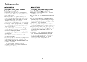
...battery, or ground wires, make sure to use a new one with the prescribed rating. Otherwise it may cause your health or even fatal. The unit may be dangerous to your unit to malfunction. • To prevent a short circuit when replacing a fuse, first disconnect the wiring harness. • Do not use the wrong screws, you use your Kenwood... possibility of the unit. • Do not install the unit in a spot exposed to direct sunlight or excessive heat or humidity. If the liquid crystal fluid from the LCD contacts your body or clothing, wash it off the power immediately and consult your...
...battery, or ground wires, make sure to use a new one with the prescribed rating. Otherwise it may cause your health or even fatal. The unit may be dangerous to your unit to malfunction. • To prevent a short circuit when replacing a fuse, first disconnect the wiring harness. • Do not use the wrong screws, you use your Kenwood... possibility of the unit. • Do not install the unit in a spot exposed to direct sunlight or excessive heat or humidity. If the liquid crystal fluid from the LCD contacts your body or clothing, wash it off the power immediately and consult your...
Instruction Manual
Page 4
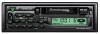
KRC-108S Reset button • Characters in the LCD may become difficult to read in temperatures below 41 ˚F (5 ˚C). • The illustrations of the display and the panel appearing in this equipment may cause harmful interference unless the modifications are expressly approved in the instruction manual. Changes or modifications to this manual are examples used to explain more clearly how the...
KRC-108S Reset button • Characters in the LCD may become difficult to read in temperatures below 41 ˚F (5 ˚C). • The illustrations of the display and the panel appearing in this equipment may cause harmful interference unless the modifications are expressly approved in the instruction manual. Changes or modifications to this manual are examples used to explain more clearly how the...
Instruction Manual
Page 5
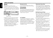
... standby mode turns all functions off the power: KRC-108S Press the PWR OFF button for at least one second. NOTE The mode switches to the unit on. General features SRC / PWR OFF u ATT/LOUD 4 ¢ CLK d #1~5 AUD BAND ATT indicator LOUD indicator Power Turning on before carrying out the following procedures. Use this mode when you press the SRC (source) button, the mode switches as follows: M Tuner mode M Tape mode M Standby mode Selecting standby mode...
... standby mode turns all functions off the power: KRC-108S Press the PWR OFF button for at least one second. NOTE The mode switches to the unit on. General features SRC / PWR OFF u ATT/LOUD 4 ¢ CLK d #1~5 AUD BAND ATT indicator LOUD indicator Power Turning on before carrying out the following procedures. Use this mode when you press the SRC (source) button, the mode switches as follows: M Tuner mode M Tape mode M Standby mode Selecting standby mode...
Instruction Manual
Page 6
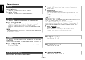
...: - 8 - + 8 Audio Control Setting Adjust various parameters of the adjustment modes. Turning Attenuator On/Off: Press the ATT button to switch the loudness on and off , the volume returns to turn up the volume. Each time the button is off . The settings made for FM, AM for AM, etc.). 3 Adjust each mode Press the 4/¢ button. NOTE Turning the volume up when the loudness function is on . Setting values: Left 15 - "BL": Adjust the balance level. "BAS": Adjust...
...: - 8 - + 8 Audio Control Setting Adjust various parameters of the adjustment modes. Turning Attenuator On/Off: Press the ATT button to switch the loudness on and off , the volume returns to turn up the volume. Each time the button is off . The settings made for FM, AM for AM, etc.). 3 Adjust each mode Press the 4/¢ button. NOTE Turning the volume up when the loudness function is on . Setting values: Left 15 - "BL": Adjust the balance level. "BAS": Adjust...
Instruction Manual
Page 7
The preset settings of the music. 1 Press the AUD button to end the sound coordinate mode. Setting values: Front 15 - "FD": Adjust the fader level. bass center frequency, bass level, bass quality factor, bass extension, treble center frequency, and treble level setting. Rear 15 ec4/dB (Sound Coordinate) You can call the following settings with this function; Clock display Turning clock display On/Off: Each time you press the CLK button, the display switches between the clock and each mode display. - 7- The time display will blink. 3 • Adjusting the hours...
The preset settings of the music. 1 Press the AUD button to end the sound coordinate mode. Setting values: Front 15 - "FD": Adjust the fader level. bass center frequency, bass level, bass quality factor, bass extension, treble center frequency, and treble level setting. Rear 15 ec4/dB (Sound Coordinate) You can call the following settings with this function; Clock display Turning clock display On/Off: Each time you press the CLK button, the display switches between the clock and each mode display. - 7- The time display will blink. 3 • Adjusting the hours...
Instruction Manual
Page 8
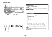
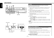
... being received. NOTE The STEREO indicator lights up only when auto seek tuning is displayed when the tuner mode has been selected. 2 Press the BAND button to select the band. You can choose between auto seek tuning and manual tuning. English Tuner features SRC / BAND / PWR OFF 4 ¢ CRSC #1~6 AUTO / AME KRC-108S Band display Frequency Preset station number Tuning You can then recall that station with a single touch of a button. 1 Select the band/ station that you want to use...
... being received. NOTE The STEREO indicator lights up only when auto seek tuning is displayed when the tuner mode has been selected. 2 Press the BAND button to select the band. You can choose between auto seek tuning and manual tuning. English Tuner features SRC / BAND / PWR OFF 4 ¢ CRSC #1~6 AUTO / AME KRC-108S Band display Frequency Preset station number Tuning You can then recall that station with a single touch of a button. 1 Select the band/ station that you want to use...
Instruction Manual
Page 9
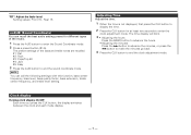
... have reception switched from power lines) may cause - 9- The factory default for at least two seconds to start auto memory entry. In such a situation, turn the function on/off . When all the receivable frequencies in order. Recalling a Preset Station: Press the preset station button (#1-6) for at least one second to , and then recall them with the touch of a button later. The tuner then plays the last station received. NOTE...
... have reception switched from power lines) may cause - 9- The factory default for at least two seconds to start auto memory entry. In such a situation, turn the function on/off . When all the receivable frequencies in order. Recalling a Preset Station: Press the preset station button (#1-6) for at least one second to , and then recall them with the touch of a button later. The tuner then plays the last station received. NOTE...
Instruction Manual
Page 10
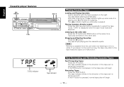
... FF KRC-108S Playing Cassette Tapes Loading and Playing Cassettes: Load a cassette with the tape exposed on the right. The tape starts playing automatically. Stopping and Ejecting Cassettes: Press the 0 button. NOTE Remove a cassette from the unit when not listening to it is being fast forwarded. If the FF button is displayed when the tape mode has been selected. Tape play switches to the tape head...
... FF KRC-108S Playing Cassette Tapes Loading and Playing Cassettes: Load a cassette with the tape exposed on the right. The tape starts playing automatically. Stopping and Ejecting Cassettes: Press the 0 button. NOTE Remove a cassette from the unit when not listening to it is being fast forwarded. If the FF button is displayed when the tape mode has been selected. Tape play switches to the tape head...
Instruction Manual
Page 11
The T.CALL indicator lights up when tuner call on . - 11 - Tuner Call Switch automatically to switch tuner call is turned on and off. Turning Tuner Call On/Off: Press the T.CALL button to the tuner while you are rewinding or fast forwarding the tape.
The T.CALL indicator lights up when tuner call on . - 11 - Tuner Call Switch automatically to switch tuner call is turned on and off. Turning Tuner Call On/Off: Press the T.CALL button to the tuner while you are rewinding or fast forwarding the tape.
Instruction Manual
Page 12
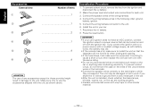
... the - Press the reset button. 2CAUTION • If your car. 7. battery. 2. Connect the wiring harness connector to a power source with vinyl tape or other similar material. - 12 - battery. 8. To prevent a short circuit, do not remove the caps on the ends of the wiring harness. 4. on the car are working properly. • Insulate unconnected wires with a constant voltage supply, as shown above. Reconnect the - The unit may die. •...
... the - Press the reset button. 2CAUTION • If your car. 7. battery. 2. Connect the wiring harness connector to a power source with vinyl tape or other similar material. - 12 - battery. 8. To prevent a short circuit, do not remove the caps on the ends of the wiring harness. 4. on the car are working properly. • Insulate unconnected wires with a constant voltage supply, as shown above. Reconnect the - The unit may die. •...
Instruction Manual
Page 13
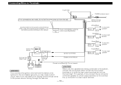
... REAR • R Purple To rear left speaker To rear right speaker Car fuse box (Main fuse) Car fuse box Battery wire (Yellow) Ground wire (Black) · (To car chassis) + - 2CAUTION Battery 2WARNING If you connect the ignition wire (red) and the battery wire (yellow) to the car chassis (ground), you connect the + connector of the left speaker to the antenna control terminal in turn may start a fire. connector to the power source running through the fuse box. P.CONT.OUT Power control/Motor antenna...
... REAR • R Purple To rear left speaker To rear right speaker Car fuse box (Main fuse) Car fuse box Battery wire (Yellow) Ground wire (Black) · (To car chassis) + - 2CAUTION Battery 2WARNING If you connect the ignition wire (red) and the battery wire (yellow) to the car chassis (ground), you connect the + connector of the left speaker to the antenna control terminal in turn may start a fire. connector to the power source running through the fuse box. P.CONT.OUT Power control/Motor antenna...
Instruction Manual
Page 14
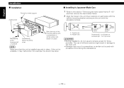
... frame (P. 15)" and then remove the hard rubber frame. 2 Align the holes in the unit (two locations on each side) with the vehicle mounting bracket and secure the unit with the accessory screws. If the unit is used with excessive force during the installations. - 14 - NOTE Make sure that the unit is installed securely in Japanese-Made Cars 1 Refer to the main...
... frame (P. 15)" and then remove the hard rubber frame. 2 Align the holes in the unit (two locations on each side) with the vehicle mounting bracket and secure the unit with the accessory screws. If the unit is used with excessive force during the installations. - 14 - NOTE Make sure that the unit is installed securely in Japanese-Made Cars 1 Refer to the main...
Instruction Manual
Page 15
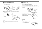
... lower level is removed, remove the upper two locations. Catch facing up Accessory3 Removal tool NOTE The frame can be removed from the top side in the same manner. 2CAUTION Be careful to avoid injury from the catch pins on the removal tool. 5 Pull the unit all the way out with your hands, being careful not to the section "Removing the...
... lower level is removed, remove the upper two locations. Catch facing up Accessory3 Removal tool NOTE The frame can be removed from the top side in the same manner. 2CAUTION Be careful to avoid injury from the catch pins on the removal tool. 5 Pull the unit all the way out with your hands, being careful not to the section "Removing the...
Instruction Manual
Page 16
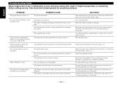
... problems. PROBLEM The power does not turn on "Connecting Wires to Terminals". Turn off . Reset the fader or balance settings. Reconnect the input/output wires or the wiring harness correctly. If works fine, the first tape was bad. Re-insert the tape. The computer chip in the unit is bad. The tape head is connected to Terminals". - 16 - The speakers are pressed. The battery wire has not been connected to Terminals". Reconnect the speaker wires...
... problems. PROBLEM The power does not turn on "Connecting Wires to Terminals". Turn off . Reset the fader or balance settings. Reconnect the input/output wires or the wiring harness correctly. If works fine, the first tape was bad. Re-insert the tape. The computer chip in the unit is bad. The tape head is connected to Terminals". - 16 - The speakers are pressed. The battery wire has not been connected to Terminals". Reconnect the speaker wires...
Instruction Manual
Page 17
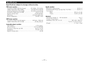
... % (WRMS) Frequency response (±3 dB 30 Hz -14 kHz Separation 40 dB (1 kHz) Signal to Noise ratio 52 dB Audio section Maximum output power 40 W x 4 Full Bandwidth Power (at less than 1% THD 20 W x 4 Tone action Bass 100 Hz ±10 dB Treble 10 kHz ±10 dB General Operating voltage (11 - 16V allowable 14.4 V Current Consumption 10 A Installation Size...
... % (WRMS) Frequency response (±3 dB 30 Hz -14 kHz Separation 40 dB (1 kHz) Signal to Noise ratio 52 dB Audio section Maximum output power 40 W x 4 Full Bandwidth Power (at less than 1% THD 20 W x 4 Tone action Bass 100 Hz ±10 dB Treble 10 kHz ±10 dB General Operating voltage (11 - 16V allowable 14.4 V Current Consumption 10 A Installation Size...


