Instructions
Page 2
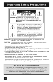
... THIS UNIT. 1. Avoid damaging the AC plug and power cord. 3. Important Safety Precautions CAUTION RISK OF ELECTRIC SHOCK DO NOT OPEN CAUTION: To reduce the risk of trouble, unplug the unit and call a service technician. No user serviceable parts inside. Operate only from the AC outlet and antenna for a long period of time, be of sufficient magnitude to environmental considerations. Avoid...
... THIS UNIT. 1. Avoid damaging the AC plug and power cord. 3. Important Safety Precautions CAUTION RISK OF ELECTRIC SHOCK DO NOT OPEN CAUTION: To reduce the risk of trouble, unplug the unit and call a service technician. No user serviceable parts inside. Operate only from the AC outlet and antenna for a long period of time, be of sufficient magnitude to environmental considerations. Avoid...
Instructions
Page 5
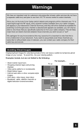
... temporary ghost image on TV off XYZ XYZ 5 Once you run the Auto Tuner Setup (which detects and programs all be marked as available, you will only be able to view those that this , mix your viewing pattern. We apologize for scanning. To avoid this is not a malfunction of time can contact your cable company for their JVC TV remote control to note that you...
... temporary ghost image on TV off XYZ XYZ 5 Once you run the Auto Tuner Setup (which detects and programs all be marked as available, you will only be able to view those that this , mix your viewing pattern. We apologize for scanning. To avoid this is not a malfunction of time can contact your cable company for their JVC TV remote control to note that you...
Instructions
Page 7
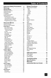
... TV 8 Using the stand 8 TV Models 9 TV Remote Control 10 Getting Started 11 The Remote Control 11 Connecting Your Devices 12 Interactive Plug In Menu 24 Programming your remote 27 Onscreen Menus 31 Using the Guide 31 Onscreen Menu System 32 Initial Setup 34 Auto Tuner Setup 34 Channel Summary 35 Channel Label 36 V-Chip 37 Set Lock Code 43 Language 44 Closed Caption 45 Auto Shut Off 47 XDS ID 47 Noise Muting 48 Front Panel Lock 48 V1 Smart Input 49 Video Input...
... TV 8 Using the stand 8 TV Models 9 TV Remote Control 10 Getting Started 11 The Remote Control 11 Connecting Your Devices 12 Interactive Plug In Menu 24 Programming your remote 27 Onscreen Menus 31 Using the Guide 31 Onscreen Menu System 32 Initial Setup 34 Auto Tuner Setup 34 Channel Summary 35 Channel Label 36 V-Chip 37 Set Lock Code 43 Language 44 Closed Caption 45 Auto Shut Off 47 XDS ID 47 Noise Muting 48 Front Panel Lock 48 V1 Smart Input 49 Video Input...
Instructions
Page 8
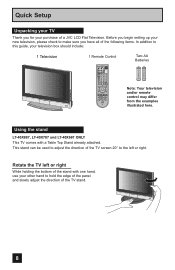
... right. Using the stand LT-40X887, LT-40X787 and LT-40X667 ONLY This TV comes with one hand, use your other hand to the left or right While holding the bottom of the stand with a Table Top Stand already attached. NATURAL SOUND CINEMA LIGHT MUTING CH GUIDE VOL OK VOL MENU BACK CH VCR CHANNEL VCR DVD PREV NEXT POWER TV VCR REW PLAY FF REC STOP PAUSE OPEN CLOSE STILL...
... right. Using the stand LT-40X887, LT-40X787 and LT-40X667 ONLY This TV comes with one hand, use your other hand to the left or right While holding the bottom of the stand with a Table Top Stand already attached. NATURAL SOUND CINEMA LIGHT MUTING CH GUIDE VOL OK VOL MENU BACK CH VCR CHANNEL VCR DVD PREV NEXT POWER TV VCR REW PLAY FF REC STOP PAUSE OPEN CLOSE STILL...
Instructions
Page 9
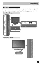
...L INPUT 1 FOR HDMI 1 AUDIOAUODIUOTOUT Side Panel Diagram POWER INPUT MENU + CHANNEL - + VOLUME - Rear Panel Diagram INPUT 3 INPUT 2 PC IN (D-SUB) Y Pr Pb VIDEO R - AUDIO - L AUDAIUODIOOUOTUT T FOR HDMI 1 INPUT 1 INPUT 2 NPUT 3 PC IN (D-SUB) Y Pr Pb VIDEO R - L Y Pr Pb S-VIDEO VIDEO OVER R - POWER 9 AUDIO - AUDIO - AUDIO - AUDIO - AUDIO - AUDIO - AUDIO - L AUDIO INPUT R L R - Quick Setup TV Models Before you in understanding how to connect your television to another device, please refer to set up your specific TV and remote...
...L INPUT 1 FOR HDMI 1 AUDIOAUODIUOTOUT Side Panel Diagram POWER INPUT MENU + CHANNEL - + VOLUME - Rear Panel Diagram INPUT 3 INPUT 2 PC IN (D-SUB) Y Pr Pb VIDEO R - AUDIO - L AUDAIUODIOOUOTUT T FOR HDMI 1 INPUT 1 INPUT 2 NPUT 3 PC IN (D-SUB) Y Pr Pb VIDEO R - L Y Pr Pb S-VIDEO VIDEO OVER R - POWER 9 AUDIO - AUDIO - AUDIO - AUDIO - AUDIO - AUDIO - AUDIO - L AUDIO INPUT R L R - Quick Setup TV Models Before you in understanding how to connect your television to another device, please refer to set up your specific TV and remote...
Instructions
Page 10
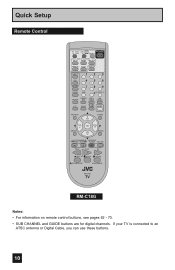
... TV is connected to an ATSC antenna or Digital Cable, you can use these buttons. 10 Quick Setup Remote Control TV CATV VCR DVD POWER ASPECT MULTI SCREEN SPLIT INDEX SELECT FREEZE SWAP DISPLAY INPUT 12 3 D/A 45 6 ML/MTS 78 9 SLEEP TUNE 0 RETURN+/TV THEATER VIDEO SUB FAVORITE PRO STATUS CHANNEL C.C. NATURAL SOUND CINEMA LIGHT MUTING CH GUIDE VOL OK VOL MENU BACK CH VCR CHANNEL VCR DVD PREV NEXT POWER TV VCR REW PLAY FF REC STOP PAUSE OPEN CLOSE...
... TV is connected to an ATSC antenna or Digital Cable, you can use these buttons. 10 Quick Setup Remote Control TV CATV VCR DVD POWER ASPECT MULTI SCREEN SPLIT INDEX SELECT FREEZE SWAP DISPLAY INPUT 12 3 D/A 45 6 ML/MTS 78 9 SLEEP TUNE 0 RETURN+/TV THEATER VIDEO SUB FAVORITE PRO STATUS CHANNEL C.C. NATURAL SOUND CINEMA LIGHT MUTING CH GUIDE VOL OK VOL MENU BACK CH VCR CHANNEL VCR DVD PREV NEXT POWER TV VCR REW PLAY FF REC STOP PAUSE OPEN CLOSE...
Instructions
Page 11
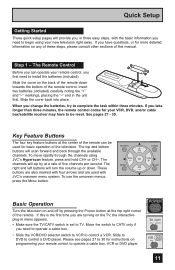
..., the remote control codes for more detailed information on programming your new television right away. MUTING CH GUIDE VOL OK VOL MENU BACK CH VCR CHANNEL VCR DVD Basic Operation Turn the television on and off by at the center of this is set to control a VCR. Slide to DVD to operate a cable box, VCR or DVD player. Step 1 - Move the switch to CATV only if you need to be used with the...
..., the remote control codes for more detailed information on programming your new television right away. MUTING CH GUIDE VOL OK VOL MENU BACK CH VCR CHANNEL VCR DVD Basic Operation Turn the television on and off by at the center of this is set to control a VCR. Slide to DVD to operate a cable box, VCR or DVD player. Step 1 - Move the switch to CATV only if you need to be used with the...
Instructions
Page 14
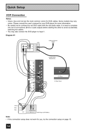
... work for DVD cables. Diagram #1 IN OUT V LR VCR IN OUT Cable or Antenna Output OR INPUT 3 INPUT 2 Y Pr Pb VIDEO R - AUDIO - L S-VIDEO VIDEO OVER R - Quick Setup VCR Connection Notes: • Green, blue and red are the most common colors for you, try the connection setup on page 15. 14 L Y Pr Pb S-VIDEO VIDEO OVER R - Please consult the user's manual for your DVD player for more information. • Be careful not to Input 1. It is best to complete one set...
... work for DVD cables. Diagram #1 IN OUT V LR VCR IN OUT Cable or Antenna Output OR INPUT 3 INPUT 2 Y Pr Pb VIDEO R - AUDIO - L S-VIDEO VIDEO OVER R - Quick Setup VCR Connection Notes: • Green, blue and red are the most common colors for you, try the connection setup on page 15. 14 L Y Pr Pb S-VIDEO VIDEO OVER R - Please consult the user's manual for your DVD player for more information. • Be careful not to Input 1. It is best to complete one set...
Instructions
Page 17
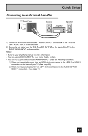
... Speaker A UDIOAUODIUOT OUT 1) Connect a white cable from the LEFT AUDIO OUTPUT on the back of the TV to the LEFT AUDIO INPUT on the amplifier. 2) Connect a red cable from the RIGHT AUDIO OUTPUT on the back of your TV. (See page 20). 2) When you have analog sound from an HDMI device connected to the HDMI 1 or HDMI 2 connection on the back of the TV to an External Amplifier TV Rear Panel R - AUDIO - Notes: • Refer to your amplifier's manual...
... Speaker A UDIOAUODIUOT OUT 1) Connect a white cable from the LEFT AUDIO OUTPUT on the back of the TV to the LEFT AUDIO INPUT on the amplifier. 2) Connect a red cable from the RIGHT AUDIO OUTPUT on the back of your TV. (See page 20). 2) When you have analog sound from an HDMI device connected to the HDMI 1 or HDMI 2 connection on the back of the TV to an External Amplifier TV Rear Panel R - AUDIO - Notes: • Refer to your amplifier's manual...
Instructions
Page 18
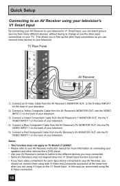
... AV Receiver's MONITOR OUT, into the VIDEO INPUT-1 on the back of your television. 3) Connect a Green Component Cable from the AV Receiver's Y MONITOR OUT, into the Y VIDEO INPUT-1 on the back of your television. 4) Connect a Blue Component Cable from the AV Receiver's PB MONITOR OUT, into the Pb VIDEO INPUT-1 on the back of your television. 5) Connect a Red Component Cable from many different devices, without having to change or use the other devices like a DVD player. • Use your AV Receiver's remote to switch...
... AV Receiver's MONITOR OUT, into the VIDEO INPUT-1 on the back of your television. 3) Connect a Green Component Cable from the AV Receiver's Y MONITOR OUT, into the Y VIDEO INPUT-1 on the back of your television. 4) Connect a Blue Component Cable from the AV Receiver's PB MONITOR OUT, into the Pb VIDEO INPUT-1 on the back of your television. 5) Connect a Red Component Cable from many different devices, without having to change or use the other devices like a DVD player. • Use your AV Receiver's remote to switch...
Instructions
Page 19
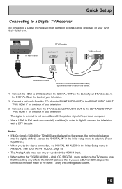
... slightly shifted. ANALOG / DIGITAL" menu setting on your television. • The digital-in terminal is not compatible with the picture signal of a personal computer. • Use a HDMI to DVI cable (commercially available) in the Initial Setup menu to ANALOG. Quick Setup Connecting to a Digital TV Receiver By connecting a Digital TV Receiver, high definition pictures can only be used with the HDMI 1 input. • When setting the "DIGITAL AUDIO - TV Rear Panel DTV Decoder DIGITAL OUT AUDIO OUT L R FOR HDMI 1 TV Rear Panel R AUDIO INPUT L S-VIDEO VIDEO REC OUT HDMI to DVI...
... slightly shifted. ANALOG / DIGITAL" menu setting on your television. • The digital-in terminal is not compatible with the picture signal of a personal computer. • Use a HDMI to DVI cable (commercially available) in the Initial Setup menu to ANALOG. Quick Setup Connecting to a Digital TV Receiver By connecting a Digital TV Receiver, high definition pictures can only be used with the HDMI 1 input. • When setting the "DIGITAL AUDIO - TV Rear Panel DTV Decoder DIGITAL OUT AUDIO OUT L R FOR HDMI 1 TV Rear Panel R AUDIO INPUT L S-VIDEO VIDEO REC OUT HDMI to DVI...
Instructions
Page 20
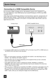
... connection, set -top box, DVD player, A/V receiver or an audio and/or video monitor, such as a set DIGITAL-IN1 AUDIO in the Initial Setup menu to a HDMI Compatible Device By connecting a HDMI compatible device, high definition pictures can be some distortion for a short time until the signal becomes stable. • When you are viewing the images from the other device conected to the "FOR HDMI 1" jacks, while you have connected when it , and blocks the analog audio signal...
... connection, set -top box, DVD player, A/V receiver or an audio and/or video monitor, such as a set DIGITAL-IN1 AUDIO in the Initial Setup menu to a HDMI Compatible Device By connecting a HDMI compatible device, high definition pictures can be some distortion for a short time until the signal becomes stable. • When you are viewing the images from the other device conected to the "FOR HDMI 1" jacks, while you have connected when it , and blocks the analog audio signal...
Instructions
Page 25
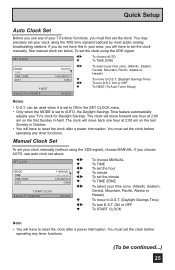
... the MODE is set to ON in October. • You will have to reset the clock after a power interruption. You may precisely set your clock using the XDS signal), choose MANUAL. See manual clock set above. ON or OFF To NEXT (To Auto Tuner Setup) SELECT OPERATE MENU EXIT Notes: • D.S.T. You must first set the clock. Quick Setup Auto Clock Set Before you use any of your TV's timer functions, you must set...
... the MODE is set to ON in October. • You will have to reset the clock after a power interruption. You may precisely set your clock using the XDS signal), choose MANUAL. See manual clock set above. ON or OFF To NEXT (To Auto Tuner Setup) SELECT OPERATE MENU EXIT Notes: • D.S.T. You must first set the clock. Quick Setup Auto Clock Set Before you use any of your TV's timer functions, you must set...
Instructions
Page 33
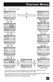
... OPERATE (2/3) MENU EXIT PICTURE ADJUST 02 INITIAL SETUP PREVIOUS AUTO TUNER SETUP CHANNEL SUMMARY V-CHIP SET LOCK CODE NEXT PAGE SELECT OPERATE (4/5) MENU EXIT INITIAL SETUP 04 INITIAL SETUP PREVIOUS LANGUAGE ENG. FRAN. CLOSED CAPTION AUTO SHUT OFF OFF XDS ID ON NEXT PAGE SELECT OPERATE (3/5) MENU EXIT INITIAL SETUP 03 INITIAL SETUP PREVIOUS NOISE MUTING FRONT PANEL LOCK V1 SMART INPUT VIDEO INPUT LABEL POSITION ADJUSTMENT POWER INDICATOR NEXT PAGE SELECT OPERATE ON OFF ON LOW (2/5) MENU EXIT INITIAL SETUP 02 PICTURE ADJUST PREVIOUS DIGITAL...
... OPERATE (2/3) MENU EXIT PICTURE ADJUST 02 INITIAL SETUP PREVIOUS AUTO TUNER SETUP CHANNEL SUMMARY V-CHIP SET LOCK CODE NEXT PAGE SELECT OPERATE (4/5) MENU EXIT INITIAL SETUP 04 INITIAL SETUP PREVIOUS LANGUAGE ENG. FRAN. CLOSED CAPTION AUTO SHUT OFF OFF XDS ID ON NEXT PAGE SELECT OPERATE (3/5) MENU EXIT INITIAL SETUP 03 INITIAL SETUP PREVIOUS NOISE MUTING FRONT PANEL LOCK V1 SMART INPUT VIDEO INPUT LABEL POSITION ADJUSTMENT POWER INDICATOR NEXT PAGE SELECT OPERATE ON OFF ON LOW (2/5) MENU EXIT INITIAL SETUP 02 PICTURE ADJUST PREVIOUS DIGITAL...
Instructions
Page 36
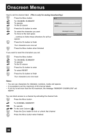
...; Press the MENU button To CHANNEL SUMMARY To operate To the ID column Press the OK button to enter To select RESET Press the OK button to finish Your characters are now set more than the 40 maximum, the message "MEMORY OVERFLOW" will appear. You can use characters for: Alphabet, numbers, marks and spaces. • It is only for analog broadcasting.) π...
...; Press the MENU button To CHANNEL SUMMARY To operate To the ID column Press the OK button to enter To select RESET Press the OK button to finish Your characters are now set more than the 40 maximum, the message "MEMORY OVERFLOW" will appear. You can use characters for: Alphabet, numbers, marks and spaces. • It is only for analog broadcasting.) π...
Instructions
Page 45
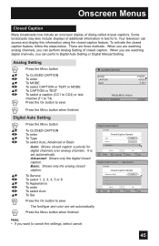
... font/type and color are watching digital channels, you are set automatically. Your television can perform Analog Setting of dialog called closed captions. To Service To select 1, 2, 3, 4, 5 or 6 To Appearance To enter To select Auto To Set Preview Closed Caption Sample Type Service Appearance AUTO 1 Cancel Select Set BACK Operate Back MENU Exit Digital Closed Caption > Appearance Preview Closed Caption Sample Appearance Mode Font Colors Opacities Cancel Select Operate Auto Set BACK Back MENU Exit Press the OK button to cancel the settings, select...
... font/type and color are watching digital channels, you are set automatically. Your television can perform Analog Setting of dialog called closed captions. To Service To select 1, 2, 3, 4, 5 or 6 To Appearance To enter To select Auto To Set Preview Closed Caption Sample Type Service Appearance AUTO 1 Cancel Select Set BACK Operate Back MENU Exit Digital Closed Caption > Appearance Preview Closed Caption Sample Appearance Mode Font Colors Opacities Cancel Select Operate Auto Set BACK Back MENU Exit Press the OK button to cancel the settings, select...
Instructions
Page 46
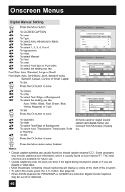
... found on closed caption channel CC1. The other channels are available for digital closed caption and digital menus are licensed from Monotype Imaging Inc. See page 68. • When ZOOM aspects like Auto, White, Black, Red, Green, Blue, Yellow, Magenta or Cyan To Set Press the OK button to save Digital Closed Caption > Appearance Preview Closed Caption Sample Appearance ModeText Manual White Font Edge White Colors Background Black Opacities Cancel Set Cancel Set Select BACK Operate Back MENU Exit...
... found on closed caption channel CC1. The other channels are available for digital closed caption and digital menus are licensed from Monotype Imaging Inc. See page 68. • When ZOOM aspects like Auto, White, Black, Red, Green, Blue, Yellow, Magenta or Cyan To Set Press the OK button to save Digital Closed Caption > Appearance Preview Closed Caption Sample Appearance ModeText Manual White Font Edge White Colors Background Black Opacities Cancel Set Cancel Set Select BACK Operate Back MENU Exit...
Instructions
Page 66
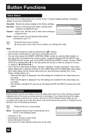
Resets the picture display to video when viewing in the following cases: • Turning on the side panel and choose a mode by using the MENU button on film (such as an SD signal. Each video status setting has a separate memory for each input connected to "AUTO" in a dimly lit room. When an HD signal is displayed: Your HD settings are recalled for the video status you are using . - When an SD signal is displayed: Your SD...
Resets the picture display to video when viewing in the following cases: • Turning on the side panel and choose a mode by using the MENU button on film (such as an SD signal. Each video status setting has a separate memory for each input connected to "AUTO" in a dimly lit room. When an HD signal is displayed: Your HD settings are recalled for the video status you are using . - When an SD signal is displayed: Your SD...
Instructions
Page 75
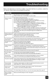
... antenna connection. See page 67. Remote control is not operating properly or at all • Check to a coaxial cable connection which is damaged, replace it , and blocks the analog audio signal coming into the wall outlet again and operating the television. • The power was interrupted and the clock was set improperly. There are lines across the picture • There could be set . Stereo or bilingual programs can not output audio using...
... antenna connection. See page 67. Remote control is not operating properly or at all • Check to a coaxial cable connection which is damaged, replace it , and blocks the analog audio signal coming into the wall outlet again and operating the television. • The power was interrupted and the clock was set improperly. There are lines across the picture • There could be set . Stereo or bilingual programs can not output audio using...
Instructions
Page 77
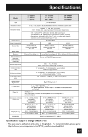
Specifications Model Type Reception Format Reception Range Power Source Power Consumption Screen Size Audio Output Speakers Antenna Terminal (VHF/UHF, ATSC/DIGITAL CABLE IN) External Input Jacks Component Input Jack S-Video Input Jacks Audio Output Jacks (FIX) Optical Output Digital Audio PC Input Jack Digital-In Dimensions (inch/cm) W X H X D Weight (lbs / kg) Accessories LT-32X887 LT-32X787 LT-32X667 LT-37X887 LT-37X787 LT-37XM57 LCD Flat Television LT-40X887 LT-40X787 LT-40X667 NTSC, BTSC System (Multi-Channel Sound) ATSC Terrestrial, Digital Cable VHF 2 to 13, UHF 14 to 69 at ATSC,...
Specifications Model Type Reception Format Reception Range Power Source Power Consumption Screen Size Audio Output Speakers Antenna Terminal (VHF/UHF, ATSC/DIGITAL CABLE IN) External Input Jacks Component Input Jack S-Video Input Jacks Audio Output Jacks (FIX) Optical Output Digital Audio PC Input Jack Digital-In Dimensions (inch/cm) W X H X D Weight (lbs / kg) Accessories LT-32X887 LT-32X787 LT-32X667 LT-37X887 LT-37X787 LT-37XM57 LCD Flat Television LT-40X887 LT-40X787 LT-40X667 NTSC, BTSC System (Multi-Channel Sound) ATSC Terrestrial, Digital Cable VHF 2 to 13, UHF 14 to 69 at ATSC,...


