User Guide
Page 18
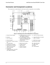
... Connector Z BIOS Control Jumper AA BIOS Select Jumper BB HDD LED Header CC HSBP Header DD Battery EE Serial B Header 4 Intel® Entry Server Board SE7221BK1-E Connections A Chassis Intrusion Header B PCI Slot C PCI-X 100 SLOT D PCI-X 100 SLOT E PCI-Express* or Riser Connector Slot ...H Back Panel I/O Connectors I EE J DD CC CPU K BB AA Socket Z DIMM 1A Socket DIMM 2A Socket DIMM 1B Socket DIMM 2B Socket Y X W V U T S R QP O N ML TP01326 Figure 2. Server Board Features Intel® Entry Server Board SE7221BK1-E User Guide Connector and Component Locations The connections you make...
... Connector Z BIOS Control Jumper AA BIOS Select Jumper BB HDD LED Header CC HSBP Header DD Battery EE Serial B Header 4 Intel® Entry Server Board SE7221BK1-E Connections A Chassis Intrusion Header B PCI Slot C PCI-X 100 SLOT D PCI-X 100 SLOT E PCI-Express* or Riser Connector Slot ...H Back Panel I/O Connectors I EE J DD CC CPU K BB AA Socket Z DIMM 1A Socket DIMM 2A Socket DIMM 1B Socket DIMM 2B Socket Y X W V U T S R QP O N ML TP01326 Figure 2. Server Board Features Intel® Entry Server Board SE7221BK1-E User Guide Connector and Component Locations The connections you make...
User Guide
Page 19
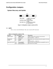
Configuration Jumper Location (J1F2) ✏ NOTE Pin 1 is from a floppy. 5 Normal operation - Table 2. Intel® Entry Server Board SE7221BK1-E User Guide Configuration Jumpers System Recovery and Update Server Board Features Figure 3. Jumper 1-2 Administrator and user passwords will be cleared on the next reset. Configuration ... 6-7 Erase RECOVERY BOOT 9-10 10-11 Normal BOOT Recovery BOOT Description CMOS settings will be attempted by loading BIOS code into flash device from the CPU side insert.
Configuration Jumper Location (J1F2) ✏ NOTE Pin 1 is from a floppy. 5 Normal operation - Table 2. Intel® Entry Server Board SE7221BK1-E User Guide Configuration Jumpers System Recovery and Update Server Board Features Figure 3. Jumper 1-2 Administrator and user passwords will be cleared on the next reset. Configuration ... 6-7 Erase RECOVERY BOOT 9-10 10-11 Normal BOOT Recovery BOOT Description CMOS settings will be attempted by loading BIOS code into flash device from the CPU side insert.
User Guide
Page 26
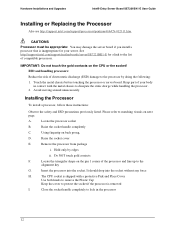
...cover E. Hardware Installations and Upgrades Intel® Entry Server Board SE7221BK1-E User Guide Installing or Replacing the Processor Also see http://support.intel.com/support/processors/pentium4/sb/CS-012311.htm. See http://support.intel.com/support/motherboards/server/SE7221BK1-E for your body in the ...prong, D. Insert the processor into the socket without any force H. Avoid moving around unnecessarily. Locate the processor socket B. The CPU socket is shipped with the metal chassis to the alignment key G. Keep part of the processor and line up to dissipate ...
...cover E. Hardware Installations and Upgrades Intel® Entry Server Board SE7221BK1-E User Guide Installing or Replacing the Processor Also see http://support.intel.com/support/processors/pentium4/sb/CS-012311.htm. See http://support.intel.com/support/motherboards/server/SE7221BK1-E for your body in the ...prong, D. Insert the processor into the socket without any force H. Avoid moving around unnecessarily. Locate the processor socket B. The CPU socket is shipped with the metal chassis to the alignment key G. Keep part of the processor and line up to dissipate ...

User Guide
Page 49
...= Fault On = 5v standby power on ƒ Off = Power is listed below. Troubleshooting Intel® Entry Server Board SE7221BK1-E User Guide Error Handling and Reporting LED Information The Intel® Server Board SE7221BK1-E includes LEDs that can be Off, Green, Amber, Red Amber Amber Amber Amber Green Correction Press...Green or Amber IDE activity Front panel Memory fault 1-4 POST code 1-4 (LSB, bit1, bit2, MSB) Fan Pack Fault CPU Fan Fault CPU Fault Identify failing memory module Display boot 80 POST code Warn on fan failure Identify fan failure Identify processor failure 5v Standby ...
...= Fault On = 5v standby power on ƒ Off = Power is listed below. Troubleshooting Intel® Entry Server Board SE7221BK1-E User Guide Error Handling and Reporting LED Information The Intel® Server Board SE7221BK1-E includes LEDs that can be Off, Green, Amber, Red Amber Amber Amber Amber Green Correction Press...Green or Amber IDE activity Front panel Memory fault 1-4 POST code 1-4 (LSB, bit1, bit2, MSB) Fan Pack Fault CPU Fan Fault CPU Fault Identify failing memory module Display boot 80 POST code Warn on fan failure Identify fan failure Identify processor failure 5v Standby ...
User Guide
Page 51
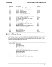
...codes. not used ) 10 CMOS Shutdown register test error 11 Invalid BIOS (such as, POST module not found) 37 System Halted CPU Speed mismatch Baseboard Management Controller failed to function Front Panel Controller failed to the operating system. Table 9. Beep Codes Number of error ...) 6 8042 GateA20 cannot be reset 3 First 64 Kb memory failure 4 Timer not operational 5 Processor failure (Reserved; Troubleshooting Intel® Entry Server Board SE7221BK1-E User Guide Error Code 153 154 8100 8110 8120 8160 8170 8180 8190 8191 8192 8193 8194 8195 8197 8300 8301 84F2 84F3...
...codes. not used ) 10 CMOS Shutdown register test error 11 Invalid BIOS (such as, POST module not found) 37 System Halted CPU Speed mismatch Baseboard Management Controller failed to function Front Panel Controller failed to the operating system. Table 9. Beep Codes Number of error ...) 6 8042 GateA20 cannot be reset 3 First 64 Kb memory failure 4 Timer not operational 5 Processor failure (Reserved; Troubleshooting Intel® Entry Server Board SE7221BK1-E User Guide Error Code 153 154 8100 8110 8120 8160 8170 8180 8190 8191 8192 8193 8194 8195 8197 8300 8301 84F2 84F3...


