User Guide
Page 3
... and replace components on using the utilities that are responsible for troubleshooting, upgrading, and repairing this chapter for step-bystep instructions and diagrams for your server: Processor, memory DIMMs, hard drive, floppy drive, CDROM or DVDROM drive, operating system. See http://support.intel.com/support/motherboards/server/se7221bk1-e/spec.htm for a link to reset the password or CMOS. This includes how to navigate through the BIOS Setup screens, how to perform a BIOS update, and how to the Technical Product Specification...
... and replace components on using the utilities that are responsible for troubleshooting, upgrading, and repairing this chapter for step-bystep instructions and diagrams for your server: Processor, memory DIMMs, hard drive, floppy drive, CDROM or DVDROM drive, operating system. See http://support.intel.com/support/motherboards/server/se7221bk1-e/spec.htm for a link to reset the password or CMOS. This includes how to navigate through the BIOS Setup screens, how to perform a BIOS update, and how to the Technical Product Specification...
User Guide
Page 4
...: http://support.intel.com/support/motherboards/server/SE7221BK1-E ƒ In-depth technical information about this product, including the BIOS settings and chipset information in the Intel® Entry Server Board SE7221BK1-E Technical Product Specification. ƒ The latest product information ƒ Accessories or other Intel® server products ƒ Hardware (peripheral boards, adapter cards) and operating systems that have been tested with this product ƒ Chassis that...
...: http://support.intel.com/support/motherboards/server/SE7221BK1-E ƒ In-depth technical information about this product, including the BIOS settings and chipset information in the Intel® Entry Server Board SE7221BK1-E Technical Product Specification. ƒ The latest product information ƒ Accessories or other Intel® server products ƒ Hardware (peripheral boards, adapter cards) and operating systems that have been tested with this product ƒ Chassis that...
User Guide
Page 7
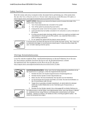
.... SAFETY STEPS: Whenever you remove the chassis covers to access the inside of the instructions. Also, there may be sharp pins and edges on some electrostatic discharge (ESD) protection by pressing the power button. 3. Do not operate the system with care. Intel® Entry Server Board SE7221BK1-E User Guide Preface Safety Cautions Read all cables connected to I /O Anschlüssen oder Ports ab. 5. Schalten Sie...
.... SAFETY STEPS: Whenever you remove the chassis covers to access the inside of the instructions. Also, there may be sharp pins and edges on some electrostatic discharge (ESD) protection by pressing the power button. 3. Do not operate the system with care. Intel® Entry Server Board SE7221BK1-E User Guide Preface Safety Cautions Read all cables connected to I /O Anschlüssen oder Ports ab. 5. Schalten Sie...
User Guide
Page 11
... Intel® Entry Server Board SE7221BK1-E User Guide 1 Server Board Features 1 Connector and Component Locations 4 Configuration Jumpers...5 System Recovery and Update 5 Back Panel Connectors ...6 Hardware Requirements...7 2 Hardware Installations and Upgrades 9 Before You Begin ...9 Tools and Supplies Needed 9 Installing and Removing Memory 10 Installing DIMMs ...10 Removing DIMMs ...11 Installing or Replacing the Processor 12 Installing the Processor 12 Removing the Processor 15 Installing a PCI, PCI-X, or PCI-Express* Card 16 Replacing the Backup Battery 17 3 Server Utilities...
... Intel® Entry Server Board SE7221BK1-E User Guide 1 Server Board Features 1 Connector and Component Locations 4 Configuration Jumpers...5 System Recovery and Update 5 Back Panel Connectors ...6 Hardware Requirements...7 2 Hardware Installations and Upgrades 9 Before You Begin ...9 Tools and Supplies Needed 9 Installing and Removing Memory 10 Installing DIMMs ...10 Removing DIMMs ...11 Installing or Replacing the Processor 12 Installing the Processor 12 Removing the Processor 15 Installing a PCI, PCI-X, or PCI-Express* Card 16 Replacing the Backup Battery 17 3 Server Utilities...

User Guide
Page 16
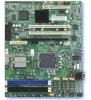
... LAN Connect (PLC) device for an Intel® Pentium® 4 processor with an 800 MHz system bus. Server Board Features Feature Processors Memory Description Support for 10/100/1000 Mbps Ethernet LAN connectivity Expansion Capabilities Four independent PCI buses 1. Server Board Features Intel® Entry Server Board SE7221BK1-E User Guide Table 1. One PCI 2.3 32-bit/33 MHz, 5 V connector supporting full length PCI add-in an LGA775 package with Intel® Hyper-Threading Technology in cards and one processor fan 2 Chipset...
... LAN Connect (PLC) device for an Intel® Pentium® 4 processor with an 800 MHz system bus. Server Board Features Feature Processors Memory Description Support for 10/100/1000 Mbps Ethernet LAN connectivity Expansion Capabilities Four independent PCI buses 1. Server Board Features Intel® Entry Server Board SE7221BK1-E User Guide Table 1. One PCI 2.3 32-bit/33 MHz, 5 V connector supporting full length PCI add-in an LGA775 package with Intel® Hyper-Threading Technology in cards and one processor fan 2 Chipset...
User Guide
Page 18
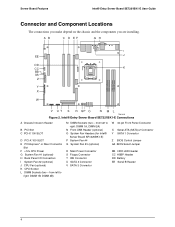
... U SATA 4 Connector V SATA 3 Connector W 34-pin Front Panel Connector X Serial ATA (SATA) 2 Connector Y SATA 1 Connector Z BIOS Control Jumper AA BIOS Select Jumper BB HDD LED Header CC HSBP Header DD Battery EE Serial B Header 4 from left to right: DIMM 1B, DIMM 2B) M DIMM Sockets (two - AB C D EF GH I System Fan #2 (optional) J CPU Fan (optional) K CPU Socket L DIMM Sockets (two - Server Board Features Intel® Entry Server Board SE7221BK1-E User Guide Connector and Component Locations The connections you make depend on the chassis and the components you are installing.
... U SATA 4 Connector V SATA 3 Connector W 34-pin Front Panel Connector X Serial ATA (SATA) 2 Connector Y SATA 1 Connector Z BIOS Control Jumper AA BIOS Select Jumper BB HDD LED Header CC HSBP Header DD Battery EE Serial B Header 4 from left to right: DIMM 1B, DIMM 2B) M DIMM Sockets (two - AB C D EF GH I System Fan #2 (optional) J CPU Fan (optional) K CPU Socket L DIMM Sockets (two - Server Board Features Intel® Entry Server Board SE7221BK1-E User Guide Connector and Component Locations The connections you make depend on the chassis and the components you are installing.
User Guide
Page 19
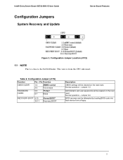
...Pin - Jumper 5-6 BIOS recovery can be attempted by loading BIOS code into flash device from the CPU side insert. This view is close to the SATA Header. Pin Function CMOS CLEAR 1-2 MBMC control 2-3 Force erase PASSWORD CLEAR 5-6 Protect 6-7 Erase RECOVERY BOOT 9-10 10-11 Normal BOOT Recovery BOOT Description CMOS settings will be cleared on the next reset. Normal operation - Table 2. Intel® Entry Server Board SE7221BK1-E User Guide Configuration Jumpers System Recovery and Update Server Board Features Figure 3. Jumper 1-2 Administrator and user passwords...
...Pin - Jumper 5-6 BIOS recovery can be attempted by loading BIOS code into flash device from the CPU side insert. This view is close to the SATA Header. Pin Function CMOS CLEAR 1-2 MBMC control 2-3 Force erase PASSWORD CLEAR 5-6 Protect 6-7 Erase RECOVERY BOOT 9-10 10-11 Normal BOOT Recovery BOOT Description CMOS settings will be cleared on the next reset. Normal operation - Table 2. Intel® Entry Server Board SE7221BK1-E User Guide Configuration Jumpers System Recovery and Update Server Board Features Figure 3. Jumper 1-2 Administrator and user passwords...
User Guide
Page 21
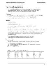
... under http://support.intel.com/support/motherboards/server/SE7221BK1-E. Processor One 2.8 GHz or greater Intel® Pentium® 4 processor in a 2x4 connector for +12v auxiliary power to Processor ƒ Split 12v rails to accurately configure memory settings for an 800 MHz system bus. For a complete list of supported memory DIMMs, see the links under the determined frequency. Power Supply The Power Supply must meet the requirements outlined below. Intel® Entry Server Board SE7221BK1-E User Guide Server Board Features...
... under http://support.intel.com/support/motherboards/server/SE7221BK1-E. Processor One 2.8 GHz or greater Intel® Pentium® 4 processor in a 2x4 connector for +12v auxiliary power to Processor ƒ Split 12v rails to accurately configure memory settings for an 800 MHz system bus. For a complete list of supported memory DIMMs, see the links under the determined frequency. Power Supply The Power Supply must meet the requirements outlined below. Intel® Entry Server Board SE7221BK1-E User Guide Server Board Features...

User Guide
Page 31
... settings stored in CMOS RAM in card. 4. WARNING There is a danger of approved devices. Discard used batteries according to pinch or damage the electrical connections when installing and removing the Bracket Assembly. 1. Be very carful not to manufacturer's instructions. Tilting card while forcing into the riser connector. Eksplosionsfare ved fejlagtig håndtering. Intel® Entry Server Board SE7221BK1-E User Guide Hardware Installations and Upgrades Rack-mount chassis add-in procedure The PCI...
... settings stored in CMOS RAM in card. 4. WARNING There is a danger of approved devices. Discard used batteries according to pinch or damage the electrical connections when installing and removing the Bracket Assembly. 1. Be very carful not to manufacturer's instructions. Tilting card while forcing into the riser connector. Eksplosionsfare ved fejlagtig håndtering. Intel® Entry Server Board SE7221BK1-E User Guide Hardware Installations and Upgrades Rack-mount chassis add-in procedure The PCI...
User Guide
Page 36
... they were before F10 was pressed without affecting any existing values. Intel® Entry Server Board SE7221BK1-E User Guide Server Utilities Key Option Description F10 Save Changes and Pressing F10 causes the following : ƒ On-board BIOS, ATA-100 RAID BIOS, and PXE option ROMs for the devices that a BIOS error occurs during the BIOS update process, see the message: Press Key if you can restore your settings from the "Load Custom Default" option. 22
... they were before F10 was pressed without affecting any existing values. Intel® Entry Server Board SE7221BK1-E User Guide Server Utilities Key Option Description F10 Save Changes and Pressing F10 causes the following : ƒ On-board BIOS, ATA-100 RAID BIOS, and PXE option ROMs for the devices that a BIOS error occurs during the BIOS update process, see the message: Press Key if you can restore your settings from the "Load Custom Default" option. 22

User Guide
Page 38
...-line Updates An Online Update is in case of operation (only for Windows version) /k - Program Boot Block n - The AMI FLASH update suite and Intel On-line updates preserve the existing BIOS image on the primary partition. The BIOS updates are updated. don't check ROM ID /pbnc - Enter Setup by pressing the F2 key during POST is completed. Rolling the BIOS also provides the ability to roll back to defaults using the F9 key...
...-line Updates An Online Update is in case of operation (only for Windows version) /k - Program Boot Block n - The AMI FLASH update suite and Intel On-line updates preserve the existing BIOS image on the primary partition. The BIOS updates are updated. don't check ROM ID /pbnc - Enter Setup by pressing the F2 key during POST is completed. Rolling the BIOS also provides the ability to roll back to defaults using the F9 key...
User Guide
Page 41
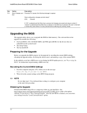
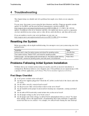
...-for assistance. Firmware upgrades include updates for components you have installed in boards sharing the same interrupt. 27 Resetting the System Before proceeding with a specific software application, see http://support.intel.com/support/motherboards/server/SE7221BK1-E for example, two add-in your system using the system. Clear system memory. Check the AC cable(s) on . Restart POST, and reload the operating system. Hardware failure is with in-depth troubleshooting, first attempt...
...-for assistance. Firmware upgrades include updates for components you have installed in boards sharing the same interrupt. 27 Resetting the System Before proceeding with a specific software application, see http://support.intel.com/support/motherboards/server/SE7221BK1-E for example, two add-in your system using the system. Clear system memory. Check the AC cable(s) on . Restart POST, and reload the operating system. Hardware failure is with in-depth troubleshooting, first attempt...
User Guide
Page 42
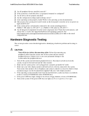
... http://support.intel.com/support/motherboards/server/SE7221BK1-E for the keyboard and the video monitor. 2. Hardware Diagnostic Testing This section provides a more detailed approach to the system and plugged into a properly grounded AC outlet. 3. Disconnect each device from the hard disk drive, make sure there is no diskette in drive A and no CD-ROM disk in Setup correct? ‰ Is the operating system properly loaded? Intel® Entry Server Board SE7221BK1-E User Guide Troubleshooting...
... http://support.intel.com/support/motherboards/server/SE7221BK1-E for the keyboard and the video monitor. 2. Hardware Diagnostic Testing This section provides a more detailed approach to the system and plugged into a properly grounded AC outlet. 3. Disconnect each device from the hard disk drive, make sure there is no diskette in drive A and no CD-ROM disk in Setup correct? ‰ Is the operating system properly loaded? Intel® Entry Server Board SE7221BK1-E User Guide Troubleshooting...

User Guide
Page 44
... the video monitor properly adjusted? ‰ Is the video monitor signal cable properly installed? ‰ Does this video monitor work correctly if plugged into a different system? 30 If you are installed only below mounting holes. Intel® Entry Server Board SE7221BK1-E User Guide Troubleshooting ‰ Some ATX power supplies have a power switch on Screen Check the following : ‰ Are the brightness and contrast controls properly adjusted on the bottom of the power supply, next to the fan...
... the video monitor properly adjusted? ‰ Is the video monitor signal cable properly installed? ‰ Does this video monitor work correctly if plugged into a different system? 30 If you are installed only below mounting holes. Intel® Entry Server Board SE7221BK1-E User Guide Troubleshooting ‰ Some ATX power supplies have a power switch on Screen Check the following : ‰ Are the brightness and contrast controls properly adjusted on the bottom of the power supply, next to the fan...

User Guide
Page 45
... plugged in response to "Disabled." Diskette Drive Activity Light Does Not Light Check the following : ‰ Are the CD-ROM/DVD-ROM drive's power and signal cables properly installed? ‰ Are all relevant switches and jumpers on the diskette drive set to the server board? ‰ Are there any of possible system component failure. Use the server management subsystem to check the fan status. ‰ Have your fans speeded up in diskette controller...
... plugged in response to "Disabled." Diskette Drive Activity Light Does Not Light Check the following : ‰ Are the CD-ROM/DVD-ROM drive's power and signal cables properly installed? ‰ Are all relevant switches and jumpers on the diskette drive set to the server board? ‰ Are there any of possible system component failure. Use the server management subsystem to check the fan status. ‰ Have your fans speeded up in diskette controller...
User Guide
Page 46
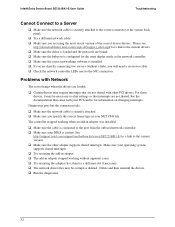
... are using the most recent version of the correct device drivers. Intel® Entry Server Board SE7221BK1-E User Guide Troubleshooting Cannot Connect to a Server ‰ Make sure the network cable is securely attached to the correct connector at the system back panel. ‰ Try a different network cable. ‰ Make sure you specify the correct frame type in your NET.CFG file. See the documentation that came with other adapter supports...
... are using the most recent version of the correct device drivers. Intel® Entry Server Board SE7221BK1-E User Guide Troubleshooting Cannot Connect to a Server ‰ Make sure the network cable is securely attached to the correct connector at the system back panel. ‰ Try a different network cable. ‰ Make sure you specify the correct frame type in your NET.CFG file. See the documentation that came with other adapter supports...

User Guide
Page 47
... user commands. 33 This means some parts of voltage spikes include a flickering video display, unexpected system reboots, and the system not responding to boot. Troubleshooting Intel® Entry Server Board SE7221BK1-E User Guide System Boots When Installing PCI Card System Server Management features require full-time "standby" power. Problems With Newly Installed Application Software Problems that occur after the system hardware and software have turned the system power off the server power by file corruption or changes...
... user commands. 33 This means some parts of voltage spikes include a flickering video display, unexpected system reboots, and the system not responding to boot. Troubleshooting Intel® Entry Server Board SE7221BK1-E User Guide System Boots When Installing PCI Card System Server Management features require full-time "standby" power. Problems With Newly Installed Application Software Problems that occur after the system hardware and software have turned the system power off the server power by file corruption or changes...
User Guide
Page 48
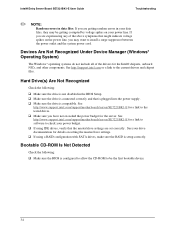
... Board SE7221BK1-E User Guide Troubleshooting ✏ NOTE: Random errors in data files: If you are getting corrupted by voltage spikes on the power line, you may want to the current drivers and chipset files. See http://www.support.intel.com/support/motherboards/server/SE7221BK1-E for a link to be getting random errors in the BIOS Setup. ‰ Make sure the drive is connected correctly and that is plugged into the power supply. ‰ Make sure the drive...
... Board SE7221BK1-E User Guide Troubleshooting ✏ NOTE: Random errors in data files: If you are getting corrupted by voltage spikes on the power line, you may want to the current drivers and chipset files. See http://www.support.intel.com/support/motherboards/server/SE7221BK1-E for a link to be getting random errors in the BIOS Setup. ‰ Make sure the drive is connected correctly and that is plugged into the power supply. ‰ Make sure the drive...

User Guide
Page 50
... CMOS Memory Size different 112 CMOS Time Not Set 140 Refresh Timer Test Failed 141 Display Memory Test Failed 142 CMOS Display Type Wrong 147 Unknown BIOS error. Error code = 14B (this is required to continue booting. Based upon the data bit availability to display Progress Code, a progress code can choose to continue. Intel® Entry Server Board SE7221BK1-E User Guide Troubleshooting BIOS Event Log The BIOS will continue booting with degraded state. User may be customized to replace faulty part...
... CMOS Memory Size different 112 CMOS Time Not Set 140 Refresh Timer Test Failed 141 Display Memory Test Failed 142 CMOS Display Type Wrong 147 Unknown BIOS error. Error code = 14B (this is required to continue booting. Based upon the data bit availability to display Progress Code, a progress code can choose to continue. Intel® Entry Server Board SE7221BK1-E User Guide Troubleshooting BIOS Event Log The BIOS will continue booting with degraded state. User may be customized to replace faulty part...
User Guide
Page 51
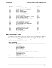
... error conditions are different Front Side Bus Speed ismatch. ATAPI Incompatible Processor Failed BIST Processor Internal Error (IERR) Processor Thermal Trip Error Processor Unable to Apply BIOS Update Processor L2 Cache Failed BIOS does not support current stepping for Processor Watchdog Timer failed on last boot 12:1 Core to inform users of Beeps Description 1 Refresh failure 2 Parity cannot be toggled (memory failure or not present) 7 Exception interrupt error 8 Display memory R/W error 9 (Reserved; ATAPI Incompatible Secondary Slave Drive - The beep code...
... error conditions are different Front Side Bus Speed ismatch. ATAPI Incompatible Processor Failed BIST Processor Internal Error (IERR) Processor Thermal Trip Error Processor Unable to Apply BIOS Update Processor L2 Cache Failed BIOS does not support current stepping for Processor Watchdog Timer failed on last boot 12:1 Core to inform users of Beeps Description 1 Refresh failure 2 Parity cannot be toggled (memory failure or not present) 7 Exception interrupt error 8 Display memory R/W error 9 (Reserved; ATAPI Incompatible Secondary Slave Drive - The beep code...


