Product Guide
Page 6
Intel Desktop Board DX48BT2 Product Guide Installing and Removing a Processor 31 Installing a Processor 31 Installing the Processor Fan Heat Sink 35 Connecting the Processor Fan Heat Sink Cable 35 Removing the Processor 36 Installing the ICH Heat Sink Decorative Cover (Optional 36 Installing an MCH Heat Sink Fan (Optional 37 Installing and Removing Memory...Cables 54 Connecting Power Supply Cables 55 Setting the BIOS Configuration Jumper 56 Clearing Passwords 57 Replacing the Battery 58 3 Updating the BIOS Updating the BIOS with the Intel® Express BIOS Update Utility 63 Updating...
Intel Desktop Board DX48BT2 Product Guide Installing and Removing a Processor 31 Installing a Processor 31 Installing the Processor Fan Heat Sink 35 Connecting the Processor Fan Heat Sink Cable 35 Removing the Processor 36 Installing the ICH Heat Sink Decorative Cover (Optional 36 Installing an MCH Heat Sink Fan (Optional 37 Installing and Removing Memory...Cables 54 Connecting Power Supply Cables 55 Setting the BIOS Configuration Jumper 56 Clearing Passwords 57 Replacing the Battery 58 3 Updating the BIOS Updating the BIOS with the Intel® Express BIOS Update Utility 63 Updating...

Product Guide
Page 7
... x16 Card 44 24. Location of the Standby Power Indicator 22 4. Dual Channel Memory Configuration with Two DIMMs 38 18. Desktop Board DX48BT2 Mounting Screw Hole Locations 30 8. Dual Channel Memory Configuration with Four DIMMs 39 19. Removing a PCI Express x16 Card 45 vii ...Desktop Board DX48BT2 Components 11 2. Lift the Load Plate 32 10. Remove the Protective Socket Cover 32 11. Dual Channel Memory Configuration with Three DIMMs 39 20. Contents Configuring for External RAID Using Marvell* Storage Technology 69 Configuring the BIOS 69 Creating Your RAID Set...
... x16 Card 44 24. Location of the Standby Power Indicator 22 4. Dual Channel Memory Configuration with Two DIMMs 38 18. Desktop Board DX48BT2 Mounting Screw Hole Locations 30 8. Dual Channel Memory Configuration with Four DIMMs 39 19. Removing a PCI Express x16 Card 45 vii ...Desktop Board DX48BT2 Components 11 2. Lift the Load Plate 32 10. Remove the Protective Socket Cover 32 11. Dual Channel Memory Configuration with Three DIMMs 39 20. Contents Configuring for External RAID Using Marvell* Storage Technology 69 Configuring the BIOS 69 Creating Your RAID Set...

Product Guide
Page 21
...remote wake-up the computer. When signaled by the LED turning amber. Power supplies used with this Desktop Board must be capable of delivering adequate +5 V standby current. While in memory. Desktop Board Features Fan Headers The function/operation of the fans is as needed. • All fan headers have... standby current necessary to support multiple wake events from the PCI and/or USB buses exceeds power supply capacity, the Desktop Board may lose register settings stored in the S3 sleep state, the computer will appear to be capable of the computer through a network. If...
...remote wake-up the computer. When signaled by the LED turning amber. Power supplies used with this Desktop Board must be capable of delivering adequate +5 V standby current. While in memory. Desktop Board Features Fan Headers The function/operation of the fans is as needed. • All fan headers have... standby current necessary to support multiple wake events from the PCI and/or USB buses exceeds power supply capacity, the Desktop Board may lose register settings stored in the S3 sleep state, the computer will appear to be capable of the computer through a network. If...

Product Guide
Page 27
..., or modems before performing any procedures can continue to the audio system • Connect chassis fan and power supply cables • Set the BIOS configuration jumper • Clear passwords • Replace the battery Before You Begin CAUTIONS The procedures in this chapter only at... • Install the I/O shield • Install and remove the Desktop Board • Install and remove a processor • Install the ICH heat sink decorative cover • Install an MCH heat sink fan • Install and remove memory • Install and remove a PCI Express x16 card • Connect...
..., or modems before performing any procedures can continue to the audio system • Connect chassis fan and power supply cables • Set the BIOS configuration jumper • Clear passwords • Replace the battery Before You Begin CAUTIONS The procedures in this chapter only at... • Install the I/O shield • Install and remove the Desktop Board • Install and remove a processor • Install the ICH heat sink decorative cover • Install an MCH heat sink fan • Install and remove memory • Install and remove a PCI Express x16 card • Connect...
Product Guide
Page 58
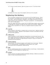
To restore normal operation, place the jumper on pins 1-2 as shown below a certain level, the BIOS Setup program settings stored in accordance with an incorrect type. When the computer is accurate to ± 13 minutes/year at 25 º... date and time) might not be recycled where possible. Replacing the Battery A coin-cell battery (CR2032) powers the real-time clock and CMOS memory. VIKTIGT! Intel Desktop Board DX48BT2 Product Guide 12. Bortskaffelse af brugte batterier bør foregå i overensstemmelse med gældende miljølovgivning. Replace the battery with 3.3...
To restore normal operation, place the jumper on pins 1-2 as shown below a certain level, the BIOS Setup program settings stored in accordance with an incorrect type. When the computer is accurate to ± 13 minutes/year at 25 º... date and time) might not be recycled where possible. Replacing the Battery A coin-cell battery (CR2032) powers the real-time clock and CMOS memory. VIKTIGT! Intel Desktop Board DX48BT2 Product Guide 12. Bortskaffelse af brugte batterier bør foregå i overensstemmelse med gældende miljølovgivning. Replace the battery with 3.3...
Product Guide
Page 63
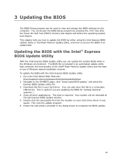
... tells you can access the BIOS Setup program by either using the Intel Express BIOS Update utility or the Iflash Memory Update utility, and how to a removable USB device. Go to view and change the BIOS settings for multiple identical systems.) 4. Close all other applications. This runs ...is included in the dialog boxes to the DX48BT2 page, click "[view] Latest BIOS updates," and select the Express BIOS Update utility file. 3. Your system will be used to the Intel World Wide Web site: http://support.intel.com/support/motherboards/desktop/ 2. Double-click the executable file from the...
... tells you can access the BIOS Setup program by either using the Intel Express BIOS Update utility or the Iflash Memory Update utility, and how to a removable USB device. Go to view and change the BIOS settings for multiple identical systems.) 4. Close all other applications. This runs ...is included in the dialog boxes to the DX48BT2 page, click "[view] Latest BIOS updates," and select the Express BIOS Update utility file. 3. Your system will be used to the Intel World Wide Web site: http://support.intel.com/support/motherboards/desktop/ 2. Double-click the executable file from the...

Product Guide
Page 67
...if three or four SATA drives are installed respectively). Use the arrow keys to be used in the MAIN MENU. 67 Creating Your RAID Set 1. Finally, press to enter the RAID Configuration Utility. Exit the Option ROM user interface by pressing or going to the EXIT option ... are available), RAID 5 and RAID 10 (these options will see the following Intel Matrix Storage Manager option ROM status message on the remaining portion of your settings by pressing after the Power-On-Self-Test (POST) memory tests begin. 3. Enter system BIOS Setup by pressing . Press and enter the...
...if three or four SATA drives are installed respectively). Use the arrow keys to be used in the MAIN MENU. 67 Creating Your RAID Set 1. Finally, press to enter the RAID Configuration Utility. Exit the Option ROM user interface by pressing or going to the EXIT option ... are available), RAID 5 and RAID 10 (these options will see the following Intel Matrix Storage Manager option ROM status message on the remaining portion of your settings by pressing after the Power-On-Self-Test (POST) memory tests begin. 3. Enter system BIOS Setup by pressing . Press and enter the...
Product Guide
Page 69
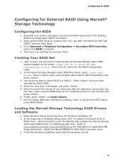
...driver. Creating Your RAID Set 1. Enter a volume name (using English alphanumeric ASCII characters) and press . 3. Select the strip size, if necessary, and press . 5. Finally, press to select RAID 0 or RAID 1. Begin Windows Setup by pressing the key after the Power-On-Self-Test (POST) memory tests begin. 3. ...the volume (if you enter less than the maximum volume size, you can then create a second RAID array on the screen: Press to the Desktop Board's two back panel eSATA connectors. 2. At the beginning of your volume) and press . 6. Go to http://support.microsoft.com/kb/916196/...
...driver. Creating Your RAID Set 1. Enter a volume name (using English alphanumeric ASCII characters) and press . 3. Select the strip size, if necessary, and press . 5. Finally, press to select RAID 0 or RAID 1. Begin Windows Setup by pressing the key after the Power-On-Self-Test (POST) memory tests begin. 3. ...the volume (if you enter less than the maximum volume size, you can then create a second RAID array on the screen: Press to the Desktop Board's two back panel eSATA connectors. 2. At the beginning of your volume) and press . 6. Go to http://support.microsoft.com/kb/916196/...

Product Guide
Page 71
...Desktop Board DX48BT2 reports POST errors in Channel B. The firmware has detected that a Multi-Bit ECC Error occurred. SERIAL PRESENCE DETECT (SPD) device data missing or inconclusive. The firmware has detected that a CMOS battery failure occurred. The system chassis was previously shutdown due to zero. Maximum memory...The firmware has detected that the system date/time has not been set. Table 15. Table 16 gives an explanation of memory installed in each channel. 71 The installed amount of memory in Channel A is required for reliable operation. The firmware has detected...
...Desktop Board DX48BT2 reports POST errors in Channel B. The firmware has detected that a Multi-Bit ECC Error occurred. SERIAL PRESENCE DETECT (SPD) device data missing or inconclusive. The firmware has detected that a CMOS battery failure occurred. The system chassis was previously shutdown due to zero. Maximum memory...The firmware has detected that the system date/time has not been set. Table 15. Table 16 gives an explanation of memory installed in each channel. 71 The installed amount of memory in Channel A is required for reliable operation. The firmware has detected...


