Product Guide
Page 3
..., such as Information Technology Equipment (I.T.E.) for use in personal computers (PC) for installation in this product for Intel® Desktop Board DX48BT2. The suitability of product features 2 Installing and Replacing Desktop Board Components: instructions on how to install the Desktop Board and other hardware components 3 Updating the BIOS: instructions on how to update the BIOS 4 Configuring for RAID: information about configuring your system for RAID A Error Messages and Indicators: information about BIOS error messages and beep codes B Regulatory Compliance...
..., such as Information Technology Equipment (I.T.E.) for use in personal computers (PC) for installation in this product for Intel® Desktop Board DX48BT2. The suitability of product features 2 Installing and Replacing Desktop Board Components: instructions on how to install the Desktop Board and other hardware components 3 Updating the BIOS: instructions on how to update the BIOS 4 Configuring for RAID: information about configuring your system for RAID A Error Messages and Indicators: information about BIOS error messages and beep codes B Regulatory Compliance...

Product Guide
Page 5
... Hardware Monitoring and Fan Speed Control 19 Intel® Precision Cooling Technology 19 Chassis Intrusion 19 Power Management 20 Software Support 20 ACPI 20 Hardware Support 20 Power Connectors 20 Fan Headers 21 LAN Wake Capabilities 21 Instantly Available PC Technology 21 +5 V Standby Power Indicator 22 Wake from USB 23 PME# Signal Wake-up Support 23 WAKE# Signal Wake-up Support 23 ENERGY STAR* Capable 23 Onboard Power Button 24 Onboard VR and CPU LEDs 25 Speaker...25 Battery ...26 Real-Time Clock 26 2 Installing and Replacing Desktop Board Components...
... Hardware Monitoring and Fan Speed Control 19 Intel® Precision Cooling Technology 19 Chassis Intrusion 19 Power Management 20 Software Support 20 ACPI 20 Hardware Support 20 Power Connectors 20 Fan Headers 21 LAN Wake Capabilities 21 Instantly Available PC Technology 21 +5 V Standby Power Indicator 22 Wake from USB 23 PME# Signal Wake-up Support 23 WAKE# Signal Wake-up Support 23 ENERGY STAR* Capable 23 Onboard Power Button 24 Onboard VR and CPU LEDs 25 Speaker...25 Battery ...26 Real-Time Clock 26 2 Installing and Replacing Desktop Board Components...
Product Guide
Page 6
... Removing a PCI Express x16 Card 45 Connecting the IDE Cable 46 Connecting the Serial ATA (SATA) Cables 47 Connecting to the Internal Headers and Connectors 48 Front Panel Audio Header 49 HD Audio Link Header 49 Consumer IR (CIR) Headers 49 Chassis Intrusion Header 50 IEEE 1394a Header 51 USB 2.0 Headers 51 Front Panel Header 52 Alternate Front Panel Power LED Header 52 S/PDIF Connector 52 Connecting to the Flexible Audio System 53 Connecting Chassis Fan and Power Supply Cables 54 Connecting Chassis Fan Cables 54 Connecting Power Supply Cables 55 Setting the BIOS Configuration...
... Removing a PCI Express x16 Card 45 Connecting the IDE Cable 46 Connecting the Serial ATA (SATA) Cables 47 Connecting to the Internal Headers and Connectors 48 Front Panel Audio Header 49 HD Audio Link Header 49 Consumer IR (CIR) Headers 49 Chassis Intrusion Header 50 IEEE 1394a Header 51 USB 2.0 Headers 51 Front Panel Header 52 Alternate Front Panel Power LED Header 52 S/PDIF Connector 52 Connecting to the Flexible Audio System 53 Connecting Chassis Fan and Power Supply Cables 54 Connecting Chassis Fan Cables 54 Connecting Power Supply Cables 55 Setting the BIOS Configuration...

Product Guide
Page 7
...84 Chassis and Component Certifications 85 Figures 1. Installing PCI Express x16 Graphics Cards 43 23. LAN Connector LEDs 16 3. Removing a PCI Express x16 Card 45 vii Onboard Power Button 24 5. Remove the Protective Socket Cover 32 11. Connecting the Processor Fan Heat Sink Cable to the Processor Fan Header ..........35 15. Lift the Load Plate 32 10. Dual Channel Memory Configuration with Three DIMMs 39 20. Desktop Board DX48BT2 Components 11 2. Contents Configuring for External RAID Using Marvell* Storage Technology 69 Configuring the BIOS 69 Creating Your RAID Set...
...84 Chassis and Component Certifications 85 Figures 1. Installing PCI Express x16 Graphics Cards 43 23. LAN Connector LEDs 16 3. Removing a PCI Express x16 Card 45 vii Onboard Power Button 24 5. Remove the Protective Socket Cover 32 11. Connecting the Processor Fan Heat Sink Cable to the Processor Fan Header ..........35 15. Lift the Load Plate 32 10. Dual Channel Memory Configuration with Three DIMMs 39 20. Desktop Board DX48BT2 Components 11 2. Contents Configuring for External RAID Using Marvell* Storage Technology 69 Configuring the BIOS 69 Creating Your RAID Set...
Product Guide
Page 8
.... Internal Headers and Connectors 48 28. Removing the Battery 62 33. Feature Summary 9 2. Safety Standards 73 18. Connecting the IDE Cable 46 26. China RoHS Environmentally Friendly Use Period Mark 80 20. Location of the BIOS Configuration Jumper Block 56 32. Back Panel CIR Header Emitter (Output) Header Signal Names 50 8. Intel Desktop Board DX48BT2 Product Guide 25. Jumper Settings for the BIOS Setup Program Modes 57 15. Connecting Power Supply Cables 55 31. LAN Connector LEDs 16 4. Beep Codes 71 16. BIOS Error Messages 71 17. USB 2.0 Header...
.... Internal Headers and Connectors 48 28. Removing the Battery 62 33. Feature Summary 9 2. Safety Standards 73 18. Connecting the IDE Cable 46 26. China RoHS Environmentally Friendly Use Period Mark 80 20. Location of the BIOS Configuration Jumper Block 56 32. Back Panel CIR Header Emitter (Output) Header Signal Names 50 8. Intel Desktop Board DX48BT2 Product Guide 25. Jumper Settings for the BIOS Setup Program Modes 57 15. Connecting Power Supply Cables 55 31. LAN Connector LEDs 16 4. Beep Codes 71 16. BIOS Error Messages 71 17. USB 2.0 Header...

Product Guide
Page 9
...supporting Intel® Matrix Storage Technology Support for Multiple PCI Express* graphics cards • Independent multi-streaming 8-channel (7.1) audio and 2-channel audio subsystem, featuring: ― Intel® High Definition Audio interface ― IDT* STAC9274D audio codec • HD Audio Link header • HD Audio front panel header • Onboard 3-pin S/PDIF connector • ADAT* optical interface support from a back panel S/PDIF optical port • Two PCI Express 2.0 x16 ports • One PCI Express 1.1 x4 port (routed to a x16 connector) • Two PCI* bus connectors...
...supporting Intel® Matrix Storage Technology Support for Multiple PCI Express* graphics cards • Independent multi-streaming 8-channel (7.1) audio and 2-channel audio subsystem, featuring: ― Intel® High Definition Audio interface ― IDT* STAC9274D audio codec • HD Audio Link header • HD Audio front panel header • Onboard 3-pin S/PDIF connector • ADAT* optical interface support from a back panel S/PDIF optical port • Two PCI Express 2.0 x16 ports • One PCI Express 1.1 x4 port (routed to a x16 connector) • Two PCI* bus connectors...

Product Guide
Page 10
... Advanced Configuration and Power Interface (ACPI) • Suspend to RAM (STR) • Wake on USB, PCI, PCI Express, LAN, CIR, and front panel • ENERGY STAR* capable Hardware Management Hardware monitor with: • Four fan sensing inputs used to monitor fan activity • Intel® Precision Cooling Technology fan speed control • Voltage sensing to detect out of range values Related Links: For more information about Desktop Board DX48BT2, including the Technical Product Specification (TPS), BIOS updates, and device drivers...
... Advanced Configuration and Power Interface (ACPI) • Suspend to RAM (STR) • Wake on USB, PCI, PCI Express, LAN, CIR, and front panel • ENERGY STAR* capable Hardware Management Hardware monitor with: • Four fan sensing inputs used to monitor fan activity • Intel® Precision Cooling Technology fan speed control • Voltage sensing to detect out of range values Related Links: For more information about Desktop Board DX48BT2, including the Technical Product Specification (TPS), BIOS updates, and device drivers...
Product Guide
Page 13
The processor connects to the Desktop Board through the LGA775 socket. Related Links: Go to the following links for Desktop Board DX48BT2, http://www.intel.com/go /findCPU • Audio software and utilities http://www.intel.com/design/motherbd • LAN software and drivers http://www.intel.com/design/motherbd Processor CAUTION Failure to use an appropriate power supply and/or not connecting the 12 V (2 x 2 pin) power connector to the Desktop Board may result in damage to the board, or...
The processor connects to the Desktop Board through the LGA775 socket. Related Links: Go to the following links for Desktop Board DX48BT2, http://www.intel.com/go /findCPU • Audio software and utilities http://www.intel.com/design/motherbd • LAN software and drivers http://www.intel.com/design/motherbd Processor CAUTION Failure to use an appropriate power supply and/or not connecting the 12 V (2 x 2 pin) power connector to the Desktop Board may result in damage to the board, or...
Product Guide
Page 15
... subsystem has the following headers and connectors: • Back panel audio connectors, including an S/PDIF optical port • High Definition (HD) Audio front panel header that provides mic in and line out signals for front panel audio connectors • HD Audio Link header used for HDMI video cards • S/PDIF connector that can be used for HDMI video cards that do not work with DMI interconnect The MCH provides interfaces to the processor, memory, PCI Express bus, and the DMI...
... subsystem has the following headers and connectors: • Back panel audio connectors, including an S/PDIF optical port • High Definition (HD) Audio front panel header that provides mic in and line out signals for front panel audio connectors • HD Audio Link header used for HDMI video cards • S/PDIF connector that can be used for HDMI video cards that do not work with DMI interconnect The MCH provides interfaces to the processor, memory, PCI Express bus, and the DMI...

Product Guide
Page 16
.../CD protocol engine • LAN connect interface between ICH9R and the LAN controller • PCI bus power management Related Links: Go to the following link for information about LAN software and drivers: http://support.intel.com/support/motherboards/desktop Two LEDs are built into the RJ-45 LAN connector located on the back panel (see Figure 2). LAN Connector LEDs Table 3 describes the LED states when the board is powered up and the LAN subsystem is occurring 10...
.../CD protocol engine • LAN connect interface between ICH9R and the LAN controller • PCI bus power management Related Links: Go to the following link for information about LAN software and drivers: http://support.intel.com/support/motherboards/desktop Two LEDs are built into the RJ-45 LAN connector located on the back panel (see Figure 2). LAN Connector LEDs Table 3 describes the LED states when the board is powered up and the LAN subsystem is occurring 10...

Product Guide
Page 17
... at USB 1.1 speeds. Enhanced IDE Interface The board's IDE interface handles the exchange of Independent Drives) levels: • RAID 0 - data striping and data mirroring • RAID 5 - data striping • RAID 1 - data mirroring • RAID 0+1 (or RAID 10) - Disabling Hi-Speed USB in the BIOS reverts all USB 2.0 ports to two onboard headers) via a discrete controller. distributed parity For information on configuring your system for RAID using Intel® Matrix Storage Technology see Chapter 4. USB 2.0 ports are backward compatible with USB 1.1 devices. USB 2.0 support...
... at USB 1.1 speeds. Enhanced IDE Interface The board's IDE interface handles the exchange of Independent Drives) levels: • RAID 0 - data striping and data mirroring • RAID 5 - data striping • RAID 1 - data mirroring • RAID 0+1 (or RAID 10) - Disabling Hi-Speed USB in the BIOS reverts all USB 2.0 ports to two onboard headers) via a discrete controller. distributed parity For information on configuring your system for RAID using Intel® Matrix Storage Technology see Chapter 4. USB 2.0 ports are backward compatible with USB 1.1 devices. USB 2.0 support...
Product Guide
Page 18
... device for booting the computer, with the following restrictions: • The supervisor password gives unrestricted access to run the BIOS Setup program after installing a Serial ATA or IDE device. The BIOS is set , you install a PCI/PCI Express add-in card. Intel Desktop Board DX48BT2 Product Guide Expandability Desktop Board DX48BT2 provides the following expansion capability: • Two PCI Express 2.0 x16 ports • One PCI Express 1.1 x4 port (routed to access Setup. Security Passwords The BIOS includes security features that add-in Chapter 3. Setup options are set...
... device for booting the computer, with the following restrictions: • The supervisor password gives unrestricted access to run the BIOS Setup program after installing a Serial ATA or IDE device. The BIOS is set , you install a PCI/PCI Express add-in card. Intel Desktop Board DX48BT2 Product Guide Expandability Desktop Board DX48BT2 provides the following expansion capability: • Two PCI Express 2.0 x16 ports • One PCI Express 1.1 x4 port (routed to access Setup. Security Passwords The BIOS includes security features that add-in Chapter 3. Setup options are set...
Product Guide
Page 19
... for a password. If only the supervisor password is booted. Desktop Board Features • Setting a user password restricts who can be compatible with the Wired for all onboard fans, that can enter either password to detect levels above and below acceptable values • Intel® Precision Cooling Technology fan speed control, delivering acoustically- If both passwords are set , the computer boots without asking for the location of power supply voltages to boot the computer. Chassis Intrusion The board supports a chassis security feature...
... for a password. If only the supervisor password is booted. Desktop Board Features • Setting a user password restricts who can be compatible with the Wired for all onboard fans, that can enter either password to detect levels above and below acceptable values • Intel® Precision Cooling Technology fan speed control, delivering acoustically- If both passwords are set , the computer boots without asking for the location of power supply voltages to boot the computer. Chassis Intrusion The board supports a chassis security feature...
Product Guide
Page 20
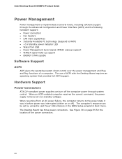
... support: • Power connectors • Fan headers • LAN wake capabilities • Instantly Available PC technology (Suspend to the power state it was interrupted (either on page 55 for the location of ACPI with the Desktop Board requires an operating system that provides full ACPI support. Hardware Support Power Connectors ATX12V-compliant power supplies can be set by using the Last Power State feature in before power was in the BIOS Setup program's Boot menu. The Desktop Board has three power connectors...
... support: • Power connectors • Fan headers • LAN wake capabilities • Instantly Available PC technology (Suspend to the power state it was interrupted (either on page 55 for the location of ACPI with the Desktop Board requires an operating system that provides full ACPI support. Hardware Support Power Connectors ATX12V-compliant power supplies can be set by using the Last Power State feature in before power was in the BIOS Setup program's Boot menu. The Desktop Board has three power connectors...

Product Guide
Page 21
... the power supply must be capable of delivering adequate +5 V standby current. Instantly Available PC technology enables the board to provide adequate standby current when using this Desktop Board must be capable of delivering adequate +5 V standby current. When signaled by the LED turning amber. Failure to its last known awake state. 21 The Desktop Board has a 4-pin processor fan header, one 4-pin and two 3-pin chassis fan headers, and one 3-pin MCH fan header. The LAN subsystem monitors network...
... the power supply must be capable of delivering adequate +5 V standby current. Instantly Available PC technology enables the board to provide adequate standby current when using this Desktop Board must be capable of delivering adequate +5 V standby current. When signaled by the LED turning amber. Failure to its last known awake state. 21 The Desktop Board has a 4-pin processor fan header, one 4-pin and two 3-pin chassis fan headers, and one 3-pin MCH fan header. The LAN subsystem monitors network...

Product Guide
Page 27
... power supply cables • Set the BIOS configuration jumper • Clear passwords • Replace the battery Before You Begin CAUTIONS The procedures in this chapter. 2 Installing and Replacing Desktop Board Components This chapter tells you how to: • Install the I/O shield • Install and remove the Desktop Board • Install and remove a processor • Install the ICH heat sink decorative cover • Install an MCH heat sink fan • Install and remove memory • Install and remove a PCI Express x16 card • Connect the IDE and Serial...
... power supply cables • Set the BIOS configuration jumper • Clear passwords • Replace the battery Before You Begin CAUTIONS The procedures in this chapter. 2 Installing and Replacing Desktop Board Components This chapter tells you how to: • Install the I/O shield • Install and remove the Desktop Board • Install and remove a processor • Install the ICH heat sink decorative cover • Install an MCH heat sink fan • Install and remove memory • Install and remove a PCI Express x16 card • Connect the IDE and Serial...

Product Guide
Page 57
... AC power source. 11. Configure (2-3) Recovery (None) After the Power-On Self-Test (POST) runs, the BIOS displays the Maintenance Menu. Press and Setup displays a pop-up screen requesting that the board is set to select Clear Passwords. Select Yes and press . Press to clear passwords. Setup displays the maintenance menu again. 9. Use the arrow keys to normal mode. 1. Replace the cover, plug in the computer and the configuration jumper block is installed in the computer, turn on pins 2-3 as...
... AC power source. 11. Configure (2-3) Recovery (None) After the Power-On Self-Test (POST) runs, the BIOS displays the Maintenance Menu. Press and Setup displays a pop-up screen requesting that the board is set to select Clear Passwords. Select Yes and press . Press to clear passwords. Setup displays the maintenance menu again. 9. Use the arrow keys to normal mode. 1. Replace the cover, plug in the computer and the configuration jumper block is installed in the computer, turn on pins 2-3 as...
Product Guide
Page 64
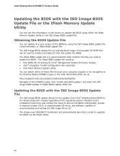
... by using the ISO Image BIOS update file (recommended), or Iflash BIOS update file. Intel Desktop Board DX48BT2 Product Guide Updating the BIOS with the ISO Image BIOS Update File The ISO Image BIOS update allows for the update of an Intel® Desktop Board BIOS to the latest production release regardless of the operating system installed on the Intel World Wide Web site at: http://support.intel.com/support/motherboards/desktop Navigate to remove the BIOS configuration jumper. Obtaining the BIOS Update File You can be used to...
... by using the ISO Image BIOS update file (recommended), or Iflash BIOS update file. Intel Desktop Board DX48BT2 Product Guide Updating the BIOS with the ISO Image BIOS Update File The ISO Image BIOS update allows for the update of an Intel® Desktop Board BIOS to the latest production release regardless of the operating system installed on the Intel World Wide Web site at: http://support.intel.com/support/motherboards/desktop Navigate to remove the BIOS configuration jumper. Obtaining the BIOS Update File You can be used to...

Product Guide
Page 68
... the Intel Matrix Storage Technology RAID Driver in : "Configuring the BIOS" and "Loading the Intel Matrix Storage Technology RAID Drivers and Software." Refer to http://support.microsoft.com/kb/916196/en-us for information on supported USB floppy disk drives. Install the Intel Matrix Storage Console software via the Intel Express Installer CD included with your Desktop Board or after downloading it from the Windows installation CD. 2. Intel Desktop Board DX48BT2 Product Guide Loading the Intel Matrix Storage Technology RAID Drivers and Software 1. Begin Windows Setup by booting...
... the Intel Matrix Storage Technology RAID Driver in : "Configuring the BIOS" and "Loading the Intel Matrix Storage Technology RAID Drivers and Software." Refer to http://support.microsoft.com/kb/916196/en-us for information on supported USB floppy disk drives. Install the Intel Matrix Storage Console software via the Intel Express Installer CD included with your Desktop Board or after downloading it from the Windows installation CD. 2. Intel Desktop Board DX48BT2 Product Guide Loading the Intel Matrix Storage Technology RAID Drivers and Software 1. Begin Windows Setup by booting...
Product Guide
Page 69
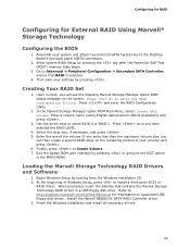
... your settings by pressing or going to the EXIT option in a USB floppy disk drive. Press and enter the RAID Configuration Utility. 2. Exit the Option ROM user interface by pressing . Loading the Marvell Storage Technology RAID Drivers and Software 1. At the beginning of your system and attach two External SATA hard drives to the Desktop Board's two back panel eSATA connectors. 2. Enter system BIOS Setup by booting from the Windows installation CD. 2. In the Marvell Storage Manager option ROM Main Menu, select: Create RAID Volume. Select the strip size...
... your settings by pressing or going to the EXIT option in a USB floppy disk drive. Press and enter the RAID Configuration Utility. 2. Exit the Option ROM user interface by pressing . Loading the Marvell Storage Technology RAID Drivers and Software 1. At the beginning of your system and attach two External SATA hard drives to the Desktop Board's two back panel eSATA connectors. 2. Enter system BIOS Setup by booting from the Windows installation CD. 2. In the Marvell Storage Manager option ROM Main Menu, select: Create RAID Volume. Select the strip size...


