
DQ67OW Technical Product Specification
Page 5
... 9 1.1.2 Board Layout 11 1.1.3 Block Diagram 13 1.2 Legacy Considerations 14 1.3 Online Support 14 1.4 Processor 14 1.5 Intel® Q67 Express Chipset 15 1.6 System Memory 15 1.6.1 Memory Configurations 16 1.7 Graphics Subsystem 18 1.7.1 Integrated Graphics 18 1.7.2 PCI Express x16 Graphics 18 1.8 USB 19 1.9 SATA Interfaces 20 1.10 Legacy I/O Controller 21 1.10.1 Serial Port 21 1.11 Audio...
... 9 1.1.2 Board Layout 11 1.1.3 Block Diagram 13 1.2 Legacy Considerations 14 1.3 Online Support 14 1.4 Processor 14 1.5 Intel® Q67 Express Chipset 15 1.6 System Memory 15 1.6.1 Memory Configurations 16 1.7 Graphics Subsystem 18 1.7.1 Integrated Graphics 18 1.7.2 PCI Express x16 Graphics 18 1.8 USB 19 1.9 SATA Interfaces 20 1.10 Legacy I/O Controller 21 1.10.1 Serial Port 21 1.11 Audio...

DQ67OW Technical Product Specification
Page 6
Intel Desktop Board DQ67OW Technical Product Specification 2.4 Intel® Management Engine BIOS Extension (Intel® MEBX) Reset Header 58 2.5 Mechanical Considerations 59 2.5.1 ...Form Factor 59 2.6 Electrical Considerations 60 2.6.1 Power Supply Considerations 60 2.6.2 Fan Header Current Capability 61 2.6.3 Add-in Board Considerations 61 2.7 Thermal Considerations 62 2.8 Reliability 64 2.9 Environmental 64 3 Overview of BIOS Features 3.1 Introduction 65 3.2 System Management BIOS (SMBIOS 67 3.3 Legacy USB...
Intel Desktop Board DQ67OW Technical Product Specification 2.4 Intel® Management Engine BIOS Extension (Intel® MEBX) Reset Header 58 2.5 Mechanical Considerations 59 2.5.1 ...Form Factor 59 2.6 Electrical Considerations 60 2.6.1 Power Supply Considerations 60 2.6.2 Fan Header Current Capability 61 2.6.3 Add-in Board Considerations 61 2.7 Thermal Considerations 62 2.8 Reliability 64 2.9 Environmental 64 3 Overview of BIOS Features 3.1 Introduction 65 3.2 System Management BIOS (SMBIOS 67 3.3 Legacy USB...
DQ67OW Technical Product Specification
Page 7
... 14. Front Panel Audio Header for a One-Color Power LED 54 26. Front Panel USB Header 48 16. Front and Rear Chassis Fan Headers 49 20. Main Power Connector 52 24. States for Intel HD Audio 47 14. Memory Channel and DIMM Configuration 17 4. Connection Diagram for AC '... Audio 48 15. Feature Summary 9 2. Front Panel Audio Header for Front Panel USB Headers 55 13. BIOS Setup Configuration Jumper Settings 57 vii Thermal Sensors and Fan Headers 27 7. Back Panel Connectors 44 10. Intel MEBX Reset Header 58 15. System Memory Map 43 9. Internal Mono Speaker Header ...
... 14. Front Panel Audio Header for a One-Color Power LED 54 26. Front Panel USB Header 48 16. Front and Rear Chassis Fan Headers 49 20. Main Power Connector 52 24. States for Intel HD Audio 47 14. Memory Channel and DIMM Configuration 17 4. Connection Diagram for AC '... Audio 48 15. Feature Summary 9 2. Front Panel Audio Header for Front Panel USB Headers 55 13. BIOS Setup Configuration Jumper Settings 57 vii Thermal Sensors and Fan Headers 27 7. Back Panel Connectors 44 10. Intel MEBX Reset Header 58 15. System Memory Map 43 9. Internal Mono Speaker Header ...
DQ67OW Technical Product Specification
Page 10
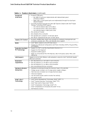
Intel Desktop Board DQ67OW Technical Product Specification Table 1. Feature Summary (continued) Peripheral Interfaces Legacy I/O Control BIOS • Fourteen USB ports: ― Six USB 2.0 ports are implemented with stacked back panel connectors (black) ― Eight USB 2.0 front panel ports are implemented through four dual-port internal headers • Six SATA interfaces through the Intel Q67 Express Chipset with...
Intel Desktop Board DQ67OW Technical Product Specification Table 1. Feature Summary (continued) Peripheral Interfaces Legacy I/O Control BIOS • Fourteen USB ports: ― Six USB 2.0 ports are implemented with stacked back panel connectors (black) ― Eight USB 2.0 front panel ports are implemented through four dual-port internal headers • Six SATA interfaces through the Intel Q67 Express Chipset with...
DQ67OW Technical Product Specification
Page 12
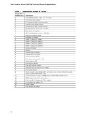
...Chassis intrusion header R Diskette drive connector S Front chassis fan header T Main power connector (2 x 12) U Standby power LED V Piezoelectric speaker W Intel Q67 Express Chipset X Alternate front panel power LED header Y Front panel header Z SATA connectors (two 6 Gb/s SATA ports (blue), two 3 ...Intel® Management Engine BIOS Extension (Intel® MEBX) Reset header BB BIOS setup configuration jumper block CC Intel Fast Call for Help (Intel FCFH) header DD Front panel USB headers (4) EE S/PDIF header FF Rear chassis fan header 12 Intel Desktop Board DQ67OW...
...Chassis intrusion header R Diskette drive connector S Front chassis fan header T Main power connector (2 x 12) U Standby power LED V Piezoelectric speaker W Intel Q67 Express Chipset X Alternate front panel power LED header Y Front panel header Z SATA connectors (two 6 Gb/s SATA ports (blue), two 3 ...Intel® Management Engine BIOS Extension (Intel® MEBX) Reset header BB BIOS setup configuration jumper block CC Intel Fast Call for Help (Intel FCFH) header DD Front panel USB headers (4) EE S/PDIF header FF Rear chassis fan header 12 Intel Desktop Board DQ67OW...
DQ67OW Technical Product Specification
Page 15
... mode support • Supports 1.2 V - 1.8 V DIMM memory voltage • Support for the board's I/O paths. Product Description 1.5 Intel® Q67 Express Chipset The Intel Q67 Express Chipset consisting of addressable memory. • Minimum total system memory: 1 GB using 1 Gb x8 module • Serial Presence Detect...or the DIMMs may not function under the determined frequency. 15 For information about The Intel Q67 Express chipset Resources used by the chipset Refer to the processor and the USB, SATA, LPC, audio, network, display, Conventional PCI, and PCI Express. The...
... mode support • Supports 1.2 V - 1.8 V DIMM memory voltage • Support for the board's I/O paths. Product Description 1.5 Intel® Q67 Express Chipset The Intel Q67 Express Chipset consisting of addressable memory. • Minimum total system memory: 1 GB using 1 Gb x8 module • Serial Presence Detect...or the DIMMs may not function under the determined frequency. 15 For information about The Intel Q67 Express chipset Resources used by the chipset Refer to the processor and the USB, SATA, LPC, audio, network, display, Conventional PCI, and PCI Express. The...
DQ67OW Technical Product Specification
Page 19
The Intel Q67 Express Chipset provides the USB controller for full-speed devices. For information about The location of the USB connectors on the back panel The location of the front panel USB headers Refer to 14 USB 2.0 ports. Product Description 1.8 USB The board supports up to Figure 9, page...Class B requirements, even if no device is as follows: • Six USB 2.0 ports are implemented with stacked back panel connectors • Eight USB 2.0 front panel ports implemented through four internal headers All 14 USB ports are high-speed, full-speed, and low-speed capable. Use a...
The Intel Q67 Express Chipset provides the USB controller for full-speed devices. For information about The location of the USB connectors on the back panel The location of the front panel USB headers Refer to 14 USB 2.0 ports. Product Description 1.8 USB The board supports up to Figure 9, page...Class B requirements, even if no device is as follows: • Six USB 2.0 ports are implemented with stacked back panel connectors • Eight USB 2.0 front panel ports implemented through four internal headers All 14 USB ports are high-speed, full-speed, and low-speed capable. Use a...

DQ67OW Technical Product Specification
Page 33
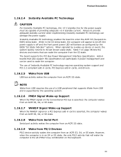
... and Power Interface (ACPI) • Hardware support: ⎯ Power connector ⎯ Fan headers ⎯ LAN wake capabilities ⎯ Instantly Available PC technology ⎯ Wake from USB ⎯ Power Management Event signal (PME#) wake-up support ⎯ PCI Express WAKE# signal support ⎯ Wake from serial port ⎯ Wake from software-based...
... and Power Interface (ACPI) • Hardware support: ⎯ Power connector ⎯ Fan headers ⎯ LAN wake capabilities ⎯ Instantly Available PC technology ⎯ Wake from USB ⎯ Power Management Event signal (PME#) wake-up support ⎯ PCI Express WAKE# signal support ⎯ Wake from serial port ⎯ Wake from software-based...
DQ67OW Technical Product Specification
Page 36
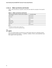
In addition, software, drivers, and peripherals must fully support ACPI wake events. 36 Power switch RTC alarm LAN USB PME# signal WAKE# signal Serial port PS/2 Notes: • S4 implies operating system support only. • USB ports are turned off during S4/S5 states. ...from this state S3, S4, S5 S3, S4, S5... S3, S4, S5 S3 S3, S4, S5 S3, S4, S5 S3 S3, S4, S5 NOTE The use of these wake-up events from specific states. Intel Desktop Board DQ67OW Technical Product Specification...
In addition, software, drivers, and peripherals must fully support ACPI wake events. 36 Power switch RTC alarm LAN USB PME# signal WAKE# signal Serial port PS/2 Notes: • S4 implies operating system support only. • USB ports are turned off during S4/S5 states. ...from this state S3, S4, S5 S3, S4, S5... S3, S4, S5 S3 S3, S4, S5 S3, S4, S5 S3 S3, S4, S5 NOTE The use of these wake-up events from specific states. Intel Desktop Board DQ67OW Technical Product Specification...
DQ67OW Technical Product Specification
Page 37
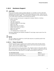
...compliant power supplies can turn off ). For information about The location of the main power connector The signal names of Wake from USB from an ACPI state requires an operating system that the power supply provides adequate +5 V standby current if LAN wake capabilities and... management hardware features, including: • Power connector • Fan headers • LAN wake capabilities • Instantly Available PC technology • Wake from USB • PME# signal wake-up support • WAKE# signal wake-up support • Wake from serial port • Wake from PS/2 •...
...compliant power supplies can turn off ). For information about The location of the main power connector The signal names of Wake from USB from an ACPI state requires an operating system that the power supply provides adequate +5 V standby current if LAN wake capabilities and... management hardware features, including: • Power connector • Fan headers • LAN wake capabilities • Instantly Available PC technology • Wake from USB • PME# signal wake-up support • WAKE# signal wake-up support • Wake from serial port • Wake from PS/2 •...
DQ67OW Technical Product Specification
Page 39
..., S4, or S5 state. 1.16.2.7 WAKE# Signal Wake-up Support When the WAKE# signal on a PCI Express add-in cards, and drivers. 1.16.2.5 Wake from USB USB bus activity wakes the computer from an ACPI S3, S4, or S5 state. When signaled by a wake-up Support When the PME# signal on the.... 1.16.2.9 Wake from PS/2 Devices PS/2 device activity wakes the computer from an ACPI S3 state. NOTE Wake from USB requires the use of a USB peripheral that can wake the computer from USB and is supported by the BIOS "S3 State Indicator" option). However, when the computer is in the S3 sleep-state...
..., S4, or S5 state. 1.16.2.7 WAKE# Signal Wake-up Support When the WAKE# signal on a PCI Express add-in cards, and drivers. 1.16.2.5 Wake from USB USB bus activity wakes the computer from an ACPI S3, S4, or S5 state. When signaled by a wake-up Support When the PME# signal on the.... 1.16.2.9 Wake from PS/2 Devices PS/2 device activity wakes the computer from an ACPI S3 state. NOTE Wake from USB requires the use of a USB peripheral that can wake the computer from USB and is supported by the BIOS "S3 State Indicator" option). However, when the computer is in the S3 sleep-state...
DQ67OW Technical Product Specification
Page 43
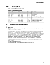
... high DOS Video me(mory andhBIOS Extended BIOS data (movable by the external devices could cause damage to the board. Furthermore, improper connection of USB header single wire connectors may eventually overload the overcurrent protection and cause damage to the computer, the power cable, and the external devices themselves. ... mem) ory Conventional memory 2.2 Connectors and Headers CAUTION Only the following connectors and headers have overcurrent protection: back panel and front panel USB, and PS/2. DFFFF 640 K - 800 K A0000 - FFFFF 896 K - 960 K E0000 - Table 8.
... high DOS Video me(mory andhBIOS Extended BIOS data (movable by the external devices could cause damage to the board. Furthermore, improper connection of USB header single wire connectors may eventually overload the overcurrent protection and cause damage to the computer, the power cable, and the external devices themselves. ... mem) ory Conventional memory 2.2 Connectors and Headers CAUTION Only the following connectors and headers have overcurrent protection: back panel and front panel USB, and PS/2. DFFFF 640 K - 800 K A0000 - FFFFF 896 K - 960 K E0000 - Table 8.
DQ67OW Technical Product Specification
Page 44
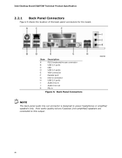
Intel Desktop Board DQ67OW Technical Product Specification 2.2.1 Back Panel Connectors Figure 9 shows the location of the back panel connectors for the board. Poor audio quality occurs if passive (non-amplified) speakers are connected to power headphones or amplified speakers only. Item A B C D E F G H I J K Description PS/2 keyboard/mouse connector USB 2.0 ports LAN USB 2.0 ports VGA connector Parallel port DVI-D connector USB 2.0 ports Audio line in Audio line out Mic in Figure 9. Back Panel Connectors NOTE The back panel audio line out connector is designed to this output. 44
Intel Desktop Board DQ67OW Technical Product Specification 2.2.1 Back Panel Connectors Figure 9 shows the location of the back panel connectors for the board. Poor audio quality occurs if passive (non-amplified) speakers are connected to power headphones or amplified speakers only. Item A B C D E F G H I J K Description PS/2 keyboard/mouse connector USB 2.0 ports LAN USB 2.0 ports VGA connector Parallel port DVI-D connector USB 2.0 ports Audio line in Audio line out Mic in Figure 9. Back Panel Connectors NOTE The back panel audio line out connector is designed to this output. 44

DQ67OW Technical Product Specification
Page 46
... fan header Diskette drive connector Main power connector (2 x 12) Alternate front panel power LED header Front panel header P SATA connectors Q Intel MEBX Reset header R Front panel USB header S Intel FCFH header T Front panel USB header U Front panel USB header V Front panel USB header W S/PDIF header X Rear chassis fan header 46 Intel Desktop Board DQ67OW Technical Product Specification Table 9.
... fan header Diskette drive connector Main power connector (2 x 12) Alternate front panel power LED header Front panel header P SATA connectors Q Intel MEBX Reset header R Front panel USB header S Intel FCFH header T Front panel USB header U Front panel USB header V Front panel USB header W S/PDIF header X Rear chassis fan header 46 Intel Desktop Board DQ67OW Technical Product Specification Table 9.
DQ67OW Technical Product Specification
Page 48
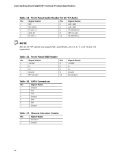
... Pin Signal Name 1 MIC 2 AUD_GND 3 MIC_BIAS 4 AUD_GND 5 FP_OUT_R 6 FP_RETURN_R 7 AUD_5V 8 KEY (no pin) 10 Signal Name +5 VDC DD+ Ground No Connect Table 16. Front Panel USB Header Pin Signal Name Pin 1 +5 VDC 2 3 D- 4 5 D+ 6 7 Ground 8 9 KEY (no pin) 9 FP_OUT_L 10 FP_RETURN_L NOTE Not all AC '97 signals are not supported...
... Pin Signal Name 1 MIC 2 AUD_GND 3 MIC_BIAS 4 AUD_GND 5 FP_OUT_R 6 FP_RETURN_R 7 AUD_5V 8 KEY (no pin) 10 Signal Name +5 VDC DD+ Ground No Connect Table 16. Front Panel USB Header Pin Signal Name Pin 1 +5 VDC 2 3 D- 4 5 D+ 6 7 Ground 8 9 KEY (no pin) 9 FP_OUT_L 10 FP_RETURN_L NOTE Not all AC '97 signals are not supported...
DQ67OW Technical Product Specification
Page 55
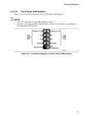
Connection Diagram for high-speed USB devices. NOTE • The +5 V DC power on the USB headers is a connection diagram for the front panel USB headers. Figure 12. Technical Reference 2.2.2.6 Front Panel USB Headers Figure 12 is fused. • Use only a front panel USB connector that conforms to the USB 2.0 specification for Front Panel USB Headers 55
Connection Diagram for high-speed USB devices. NOTE • The +5 V DC power on the USB headers is a connection diagram for the front panel USB headers. Figure 12. Technical Reference 2.2.2.6 Front Panel USB Headers Figure 12 is fused. • Use only a front panel USB connector that conforms to the USB 2.0 specification for Front Panel USB Headers 55
DQ67OW Technical Product Specification
Page 57
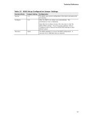
.../CMOS settings. After the POST runs, Setup runs automatically. Note that this Configure mode is the only way to their default values. A recovery CD or USB flash drive is displayed. Recovery None The BIOS attempts to recover the BIOS configuration. The maintenance menu is required. 57
.../CMOS settings. After the POST runs, Setup runs automatically. Note that this Configure mode is the only way to their default values. A recovery CD or USB flash drive is displayed. Recovery None The BIOS attempts to recover the BIOS configuration. The maintenance menu is required. 57
DQ67OW Technical Product Specification
Page 58
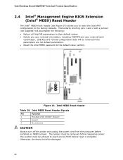
... Board DQ67OW Technical Product Specification 2.4 Intel® Management Engine BIOS Extension (Intel® MEBX) Reset Header The Intel® MEBX reset header (see Figure 14) allows you to reset the Intel AMT configuration to their default values. • Delete any user entered information, including PID/PPS and user entered Hash Certificates. USB key and remote configuration...
... Board DQ67OW Technical Product Specification 2.4 Intel® Management Engine BIOS Extension (Intel® MEBX) Reset Header The Intel® MEBX reset header (see Figure 14) allows you to reset the Intel AMT configuration to their default values. • Delete any user entered information, including PID/PPS and user entered Hash Certificates. USB key and remote configuration...
DQ67OW Technical Product Specification
Page 67
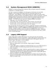
...data, such as memory size, cache size, and processor speed • Dynamic data, such as third-party management software to use a USB keyboard to Enabled. Using SMBIOS, a system administrator can obtain the SMBIOS information. Additional board information can be found in the BIOS under the... Additional Information header under the Main BIOS page. 3.3 Legacy USB Support Legacy USB support enables USB devices to be used even when the operating system's USB drivers are not recognized during this period if Legacy USB support was set to enter and configure the BIOS Setup program...
...data, such as memory size, cache size, and processor speed • Dynamic data, such as third-party management software to use a USB keyboard to Enabled. Using SMBIOS, a system administrator can obtain the SMBIOS information. Additional board information can be found in the BIOS under the... Additional Information header under the Main BIOS page. 3.3 Legacy USB Support Legacy USB support enables USB devices to be used even when the operating system's USB drivers are not recognized during this period if Legacy USB support was set to enter and configure the BIOS Setup program...
DQ67OW Technical Product Specification
Page 68
... 68 Using this utility, the BIOS can be updated from a file on a hard disk, a USB drive (a flash drive or a USB drive), or an optical drive. • Intel® Flash Memory Update Utility, which requires booting from that the updated BIOS matches the target system to... performing a BIOS Recovery without removing the BIOS configuration jumper. Intel Desktop Board DQ67OW Technical Product Specification 3.4 ...
... 68 Using this utility, the BIOS can be updated from a file on a hard disk, a USB drive (a flash drive or a USB drive), or an optical drive. • Intel® Flash Memory Update Utility, which requires booting from that the updated BIOS matches the target system to... performing a BIOS Recovery without removing the BIOS configuration jumper. Intel Desktop Board DQ67OW Technical Product Specification 3.4 ...

