
DQ67OW Technical Product Specification
Page 5
...Layout 11 1.1.3 Block Diagram 13 1.2 Legacy Considerations 14 1.3 Online Support 14 1.4 Processor 14 1.5 Intel® Q67 Express Chipset 15 1.6 System Memory 15 1.6.1 Memory Configurations 16 1.7 Graphics Subsystem 18 ...Software 22 1.11.2 Audio Headers and Connectors 22 1.12 LAN Subsystem 24 1.12.1 Intel® 82579LM Gigabit Ethernet Controller 24 1.12.2 LAN Subsystem Software 24 1.12.3 ...Management and Security 28 1.15.1 Hardware Management Subsystem 28 1.15.2 Hardware Monitoring 28 1.15.3 Intel® vPro™ Technology 29 1.16 Power Management 33 1.16.1 ACPI 34 1.16.2 ...
...Layout 11 1.1.3 Block Diagram 13 1.2 Legacy Considerations 14 1.3 Online Support 14 1.4 Processor 14 1.5 Intel® Q67 Express Chipset 15 1.6 System Memory 15 1.6.1 Memory Configurations 16 1.7 Graphics Subsystem 18 ...Software 22 1.11.2 Audio Headers and Connectors 22 1.12 LAN Subsystem 24 1.12.1 Intel® 82579LM Gigabit Ethernet Controller 24 1.12.2 LAN Subsystem Software 24 1.12.3 ...Management and Security 28 1.15.1 Hardware Management Subsystem 28 1.15.2 Hardware Monitoring 28 1.15.3 Intel® vPro™ Technology 29 1.16 Power Management 33 1.16.1 ACPI 34 1.16.2 ...

DQ67OW Technical Product Specification
Page 6
Intel Desktop Board DQ67OW Technical Product Specification 2.4 Intel® Management Engine BIOS Extension (Intel® MEBX) Reset Header 58 2.5 Mechanical Considerations 59 2.5.1 Form Factor 59 2.6 Electrical Considerations 60 2.6.1 Power Supply Considerations 60 2.6.2 ... Drive Password Security Feature 71 3.8 BIOS Security Features 72 4 Error Messages and Beep Codes 4.1 Speaker 75 4.2 BIOS Beep Codes 75 4.3 Front-panel Power LED Blink Codes 76 4.4 BIOS Error Messages 76 4.5 Port 80h POST Codes 77 5 Regulatory Compliance and Battery Disposal Information 5.1 Regulatory Compliance ...
Intel Desktop Board DQ67OW Technical Product Specification 2.4 Intel® Management Engine BIOS Extension (Intel® MEBX) Reset Header 58 2.5 Mechanical Considerations 59 2.5.1 Form Factor 59 2.6 Electrical Considerations 60 2.6.1 Power Supply Considerations 60 2.6.2 ... Drive Password Security Feature 71 3.8 BIOS Security Features 72 4 Error Messages and Beep Codes 4.1 Speaker 75 4.2 BIOS Beep Codes 75 4.3 Front-panel Power LED Blink Codes 76 4.4 BIOS Error Messages 76 4.5 Port 80h POST Codes 77 5 Regulatory Compliance and Battery Disposal Information 5.1 Regulatory Compliance ...
DQ67OW Technical Product Specification
Page 7
... Zones 63 Tables 1. Wake-up Devices and Events 36 8. S/PDIF Header 47 12. Front Panel Audio Header for a One-Color Power LED 54 26. Front Panel Header 53 25. States for Intel HD Audio 47 14. Block Diagram 13 3. Memory Channel and DIMM Configuration 17 4. Board Dimensions... 59 16. Serial Port Header 47 11. Chassis Intrusion Header 48 18. Intel FCFH Header 49 21. Location of...
... Zones 63 Tables 1. Wake-up Devices and Events 36 8. S/PDIF Header 47 12. Front Panel Audio Header for a One-Color Power LED 54 26. Front Panel Header 53 25. States for Intel HD Audio 47 14. Block Diagram 13 3. Memory Channel and DIMM Configuration 17 4. Board Dimensions... 59 16. Serial Port Header 47 11. Chassis Intrusion Header 48 18. Intel FCFH Header 49 21. Location of...
DQ67OW Technical Product Specification
Page 8
...39. BIOS Error Messages 76 42. Regulatory Compliance Marks 91 viii Fan Header Current Capability 61 31. Front-panel Power LED Blink Codes 76 41. Safety Standards 83 46. Intel MEBX Reset Header Signals 58 29. BIOS Setup Program Function Keys 66 35. Port 80h POST Codes 78 44...Types for Components 63 32. EMC Regulations 87 47. Recommended Power Supply Current Values 60 30. Boot Device Menu Options 70 37. Intel Desktop Board DQ67OW Technical Product Specification 28. Environmental Specifications 64 33. BIOS Setup Program Menu Bar 66 34. BIOS Beep Codes 75 40.
...39. BIOS Error Messages 76 42. Regulatory Compliance Marks 91 viii Fan Header Current Capability 61 31. Front-panel Power LED Blink Codes 76 41. Safety Standards 83 46. Intel MEBX Reset Header Signals 58 29. BIOS Setup Program Function Keys 66 35. Port 80h POST Codes 78 44...Types for Components 63 32. EMC Regulations 87 47. Recommended Power Supply Current Values 60 30. Boot Device Menu Options 70 37. Intel Desktop Board DQ67OW Technical Product Specification 28. Environmental Specifications 64 33. BIOS Setup Program Menu Bar 66 34. BIOS Beep Codes 75 40.
DQ67OW Technical Product Specification
Page 9
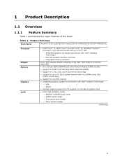
...millimeters]) Processor Chipset Memory Graphics Audio • Intel® Core™ i7, Intel® Core™ i5, Intel® Core™ i3, and Intel® Pentium® processors in an LGA1155 ...graphics processing (processors with Intel® Graphics Technology) ― External graphics interface controller ― Integrated memory controller Intel® Q67 Express Chipset consisting of the Intel® Q67 Platform Controller...ECC memory • Integrated graphics support for processors with Intel® Graphics Technology: ― VGA ― DVI-D • Discrete graphics support for ...
...millimeters]) Processor Chipset Memory Graphics Audio • Intel® Core™ i7, Intel® Core™ i5, Intel® Core™ i3, and Intel® Pentium® processors in an LGA1155 ...graphics processing (processors with Intel® Graphics Technology) ― External graphics interface controller ― Integrated memory controller Intel® Q67 Express Chipset consisting of the Intel® Q67 Platform Controller...ECC memory • Integrated graphics support for processors with Intel® Graphics Technology: ― VGA ― DVI-D • Discrete graphics support for ...
DQ67OW Technical Product Specification
Page 10
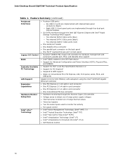
Intel Desktop Board DQ67OW Technical Product Specification Table 1. Feature Summary (continued) Peripheral Interfaces Legacy I/O Control BIOS • Fourteen USB ports: ― Six USB 2.0 ports are implemented with stacked back panel connectors (black) ― Eight USB 2.0 front panel ports are implemented through four dual-port internal headers • Six SATA interfaces through the Intel Q67 Express Chipset...
Intel Desktop Board DQ67OW Technical Product Specification Table 1. Feature Summary (continued) Peripheral Interfaces Legacy I/O Control BIOS • Fourteen USB ports: ― Six USB 2.0 ports are implemented with stacked back panel connectors (black) ― Eight USB 2.0 front panel ports are implemented through four dual-port internal headers • Six SATA interfaces through the Intel Q67 Express Chipset...
DQ67OW Technical Product Specification
Page 12
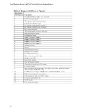
... connector S Front chassis fan header T Main power connector (2 x 12) U Standby power LED V Piezoelectric speaker W Intel Q67 Express Chipset X Alternate front panel power LED header Y Front panel header Z SATA connectors (two 6 Gb/s SATA ports (blue), two 3 Gb/s SATA ports (black), and two ...AA Intel® Management Engine BIOS Extension (Intel® MEBX) Reset header BB BIOS setup configuration jumper block CC Intel Fast Call for Help (Intel FCFH) header DD Front panel USB headers (4) EE S/PDIF header FF Rear chassis fan header 12 Intel Desktop Board DQ67OW ...
... connector S Front chassis fan header T Main power connector (2 x 12) U Standby power LED V Piezoelectric speaker W Intel Q67 Express Chipset X Alternate front panel power LED header Y Front panel header Z SATA connectors (two 6 Gb/s SATA ports (blue), two 3 Gb/s SATA ports (black), and two ...AA Intel® Management Engine BIOS Extension (Intel® MEBX) Reset header BB BIOS setup configuration jumper block CC Intel Fast Call for Help (Intel FCFH) header DD Front panel USB headers (4) EE S/PDIF header FF Rear chassis fan header 12 Intel Desktop Board DQ67OW ...
DQ67OW Technical Product Specification
Page 19
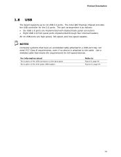
... FCC Class B requirements, even if no device is as follows: • Six USB 2.0 ports are implemented with stacked back panel connectors • Eight USB 2.0 front panel ports implemented through four internal headers All 14 USB ports are high-speed, full-speed, and low-speed capable. Use a shielded... cable that have an unshielded cable attached to the cable. The Intel Q67 Express Chipset provides the USB controller for full-...
... FCC Class B requirements, even if no device is as follows: • Six USB 2.0 ports are implemented with stacked back panel connectors • Eight USB 2.0 front panel ports implemented through four internal headers All 14 USB ports are high-speed, full-speed, and low-speed capable. Use a shielded... cable that have an unshielded cable attached to the cable. The Intel Q67 Express Chipset provides the USB controller for full-...
DQ67OW Technical Product Specification
Page 21
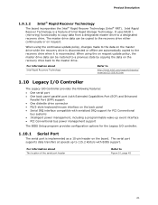
The master drive data can be copied to http://www.intel.com/support/chipsets/ imsm/sb/CS-026142.htm 1.10 Legacy I/O Controller The Legacy I/O Controller provides the following features: • One serial port • One back panel parallel port (with Extended Capabilities Port (ECP) and Enhanced ...Parallel Port (EPP) support • One diskette drive connector • PS/2-style keyboard/mouse interface on the back panel • Serial IRQ interface compatible with BIOS support. When using the on request update policy, the master drive data can be restored ...
The master drive data can be copied to http://www.intel.com/support/chipsets/ imsm/sb/CS-026142.htm 1.10 Legacy I/O Controller The Legacy I/O Controller provides the following features: • One serial port • One back panel parallel port (with Extended Capabilities Port (ECP) and Enhanced ...Parallel Port (EPP) support • One diskette drive connector • PS/2-style keyboard/mouse interface on the back panel • Serial IRQ interface compatible with BIOS support. When using the on request update policy, the master drive data can be restored ...
DQ67OW Technical Product Specification
Page 22
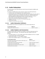
...in functions for front panel audio jacks • S/PDIF audio header • A signal-to Figure 10, page 45 Table 13 and Table 14, page 47 Table 11, page 47 Table 12, page 47 Section 2.2.1, page 44 22 Intel Desktop Board DQ67OW Technical Product Specification 1.11... Audio Subsystem The board supports Intel High Definition Audio through back panel jacks • Headphone and Mic in signals for front panel audio connectors) (yellow) • S/PDIF audio header (1 x 4-pin...
...in functions for front panel audio jacks • S/PDIF audio header • A signal-to Figure 10, page 45 Table 13 and Table 14, page 47 Table 11, page 47 Table 12, page 47 Section 2.2.1, page 44 22 Intel Desktop Board DQ67OW Technical Product Specification 1.11... Audio Subsystem The board supports Intel High Definition Audio through back panel jacks • Headphone and Mic in signals for front panel audio connectors) (yellow) • S/PDIF audio header (1 x 4-pin...
DQ67OW Technical Product Specification
Page 23
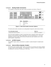
...optical dongles for digital audio output. 1.11.2.3 Internal Mono Speaker Header The internal mono speaker header allows connection to Section 2.2.1, page 44 The front panel headphone output is capable of driving a speaker load of 8 Ohms at 1 W (rms) or 4 Ohms at 1.5 W (rms). 23 ...audio conferencing (through the audio device drivers. For information about The back panel audio connectors Refer to an internal, low-power speaker for basic system sound capability. Back Panel Audio Connector Options The back panel audio connectors are shown in Figure 4. Item A B C Description ...
...optical dongles for digital audio output. 1.11.2.3 Internal Mono Speaker Header The internal mono speaker header allows connection to Section 2.2.1, page 44 The front panel headphone output is capable of driving a speaker load of 8 Ohms at 1 W (rms) or 4 Ohms at 1.5 W (rms). 23 ...audio conferencing (through the audio device drivers. For information about The back panel audio connectors Refer to an internal, low-power speaker for basic system sound capability. Back Panel Audio Connector Options The back panel audio connectors are shown in Figure 4. Item A B C Description ...
DQ67OW Technical Product Specification
Page 34
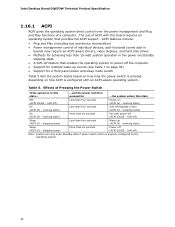
Intel Desktop Board DQ67OW Technical Product Specification 1.16.1 ACPI ACPI gives the operating system direct control over the power management and Plug and Play functions of individual devices, add-.... pressed for ...the system enters this board requires an operating system that enables the operating system to power-off the computer • Support for a front panel power and sleep mode switch Table 5 lists the system states based on how long the power switch is pressed, depending on /standby sleeping state •...
Intel Desktop Board DQ67OW Technical Product Specification 1.16.1 ACPI ACPI gives the operating system direct control over the power management and Plug and Play functions of individual devices, add-.... pressed for ...the system enters this board requires an operating system that enables the operating system to power-off the computer • Support for a front panel power and sleep mode switch Table 5 lists the system states based on how long the power switch is pressed, depending on /standby sleeping state •...
DQ67OW Technical Product Specification
Page 39
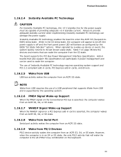
... S5 state. 1.16.2.7 WAKE# Signal Wake-up device or event, the system quickly returns to be off (the power supply is off and the front panel power LED will wake the computer is asserted, the computer wakes from an ACPI S3, S4, or S5 state. 1.16.2.8 Wake from Serial Port Serial...
... S5 state. 1.16.2.7 WAKE# Signal Wake-up device or event, the system quickly returns to be off (the power supply is off and the front panel power LED will wake the computer is asserted, the computer wakes from an ACPI S3, S4, or S5 state. 1.16.2.8 Wake from Serial Port Serial...
DQ67OW Technical Product Specification
Page 43
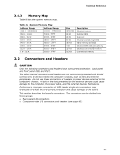
... Extended conventionfal mem) ory Conventional memory 2.2 Connectors and Headers CAUTION Only the following connectors and headers have overcurrent protection: back panel and front panel USB, and PS/2. FFFFF 896 K - 960 K E0000 - The other internal connectors and headers are not overcurrent protected ...and should connect only to the board. Do not use these groups: • Back panel I/O connectors • Component-side I/O connectors and headers (see page 45) 43 Furthermore, improper connection of USB header single wire ...
... Extended conventionfal mem) ory Conventional memory 2.2 Connectors and Headers CAUTION Only the following connectors and headers have overcurrent protection: back panel and front panel USB, and PS/2. FFFFF 896 K - 960 K E0000 - The other internal connectors and headers are not overcurrent protected ...and should connect only to the board. Do not use these groups: • Back panel I/O connectors • Component-side I/O connectors and headers (see page 45) 43 Furthermore, improper connection of USB header single wire ...
DQ67OW Technical Product Specification
Page 44
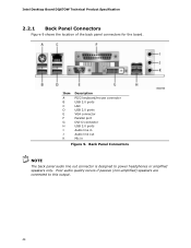
Intel Desktop Board DQ67OW Technical Product Specification 2.2.1 Back Panel Connectors Figure 9 shows the location of the back panel connectors for the board. Item A B C D E F G H I J K Description PS/2 keyboard/mouse connector USB 2.0 ports LAN USB 2.0 ports VGA connector Parallel port DVI-D connector USB 2.0 ports Audio line in Audio line out Mic in Figure 9. Back Panel Connectors NOTE The back panel audio line out connector is designed to this output. 44 Poor audio quality occurs if passive (non-amplified) speakers are connected to power headphones or amplified speakers only.
Intel Desktop Board DQ67OW Technical Product Specification 2.2.1 Back Panel Connectors Figure 9 shows the location of the back panel connectors for the board. Item A B C D E F G H I J K Description PS/2 keyboard/mouse connector USB 2.0 ports LAN USB 2.0 ports VGA connector Parallel port DVI-D connector USB 2.0 ports Audio line in Audio line out Mic in Figure 9. Back Panel Connectors NOTE The back panel audio line out connector is designed to this output. 44 Poor audio quality occurs if passive (non-amplified) speakers are connected to power headphones or amplified speakers only.

DQ67OW Technical Product Specification
Page 46
Intel Desktop Board DQ67OW Technical Product Specification Table 9. Component-side Connectors and Headers Shown in Figure 10 Item/callout from Figure 10 A B C D E F G H I J K L M N O Description Conventional PCI bus add-in card connector Front panel audio header PCI Express x4 bus add... Main power connector (2 x 12) Alternate front panel power LED header Front panel header P SATA connectors Q Intel MEBX Reset header R Front panel USB header S Intel FCFH header T Front panel USB header U Front panel USB header V Front panel USB header W S/PDIF header X Rear chassis fan...
Intel Desktop Board DQ67OW Technical Product Specification Table 9. Component-side Connectors and Headers Shown in Figure 10 Item/callout from Figure 10 A B C D E F G H I J K L M N O Description Conventional PCI bus add-in card connector Front panel audio header PCI Express x4 bus add... Main power connector (2 x 12) Alternate front panel power LED header Front panel header P SATA connectors Q Intel MEBX Reset header R Front panel USB header S Intel FCFH header T Front panel USB header U Front panel USB header V Front panel USB header W S/PDIF header X Rear chassis fan...
DQ67OW Technical Product Specification
Page 47
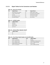
...) Key (no pin) 10 [Port 2] SENSE_RETURN 47 Internal Mono Speaker Header Pin Signal Name 1 − 2 + Table 13. Front Panel Audio Header for the Connectors and Headers Table 10. Technical Reference 2.2.2.1 Signal Tables for Intel HD Audio Pin Signal Name Pin Signal Name 1 [Port 1] Left channel 3 [Port 1] Right channel 5 [Port 2] Right channel 7 SENSE_SEND...
...) Key (no pin) 10 [Port 2] SENSE_RETURN 47 Internal Mono Speaker Header Pin Signal Name 1 − 2 + Table 13. Front Panel Audio Header for the Connectors and Headers Table 10. Technical Reference 2.2.2.1 Signal Tables for Intel HD Audio Pin Signal Name Pin Signal Name 1 [Port 1] Left channel 3 [Port 1] Right channel 5 [Port 2] Right channel 7 SENSE_SEND...
DQ67OW Technical Product Specification
Page 48
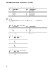
...Pin 1 +5 VDC 2 3 D- 4 5 D+ 6 7 Ground 8 9 KEY (no pin) 9 FP_OUT_L 10 FP_RETURN_L NOTE Not all AC '97 signals are not supported. Table 15. Front Panel Audio Header for AC '97 Audio Pin Signal Name Pin Signal Name 1 MIC 2 AUD_GND 3 MIC_BIAS 4 AUD_GND 5 FP_OUT_R 6 FP_RETURN_R 7 AUD_5V 8 KEY (no pin) 10 Signal Name... Pin Signal Name 1 Ground 2 TXP 3 TXN 4 Ground 5 RXN 6 RXP 7 Ground Table 17. Chassis Intrusion Header Pin Signal Name 1 Intruder# 2 Ground 48 Intel Desktop Board DQ67OW Technical Product Specification Table 14.
...Pin 1 +5 VDC 2 3 D- 4 5 D+ 6 7 Ground 8 9 KEY (no pin) 9 FP_OUT_L 10 FP_RETURN_L NOTE Not all AC '97 signals are not supported. Table 15. Front Panel Audio Header for AC '97 Audio Pin Signal Name Pin Signal Name 1 MIC 2 AUD_GND 3 MIC_BIAS 4 AUD_GND 5 FP_OUT_R 6 FP_RETURN_R 7 AUD_5V 8 KEY (no pin) 10 Signal Name... Pin Signal Name 1 Ground 2 TXP 3 TXN 4 Ground 5 RXN 6 RXP 7 Ground Table 17. Chassis Intrusion Header Pin Signal Name 1 Intruder# 2 Ground 48 Intel Desktop Board DQ67OW Technical Product Specification Table 14.
DQ67OW Technical Product Specification
Page 53
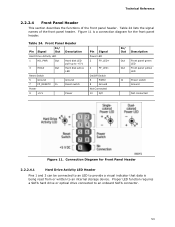
...visual indicator that data is being read from or written to an internal storage device. Connection Diagram for the front panel header. Table 24. Front Panel Header Pin Signal In/ Out Description Hard Drive Activity LED 1 HD_PWR Out Hard disk LED pull-up to an ...Ground Not Connected 10 N/C In/ Out Description Out Front panel green LED Out Front panel yellow LED In Power switch Ground Not connected Figure 11. Technical Reference 2.2.2.4 Front Panel Header This section describes the functions of the front panel header. Table 24 lists the signal names of the ...
...visual indicator that data is being read from or written to an internal storage device. Connection Diagram for the front panel header. Table 24. Front Panel Header Pin Signal In/ Out Description Hard Drive Activity LED 1 HD_PWR Out Hard disk LED pull-up to an ...Ground Not Connected 10 N/C In/ Out Description Out Front panel green LED Out Front panel yellow LED In Power switch Ground Not connected Figure 11. Technical Reference 2.2.2.4 Front Panel Header This section describes the functions of the front panel header. Table 24 lists the signal names of the ...
DQ67OW Technical Product Specification
Page 54
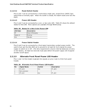
Intel Desktop Board DQ67OW Technical Product Specification 2.2.2.4.2 Reset Switch Header Pins 5 and 7 can be connected to a one- Table 25 shows the default states for at least 50 ms to signal the power supply to switch on or off. (The time requirement is due to a front panel... FP_LED− Out FP_LED+ FP_LED− 54 States for a One-Color Power LED LED State Description Off Power off signal. 2.2.2.5 Alternate Front Panel Power LED Header Pins 1 and 3 of this header duplicate the signals on /off /sleeping Steady Lit Running Blink Standby 2.2.2.4.4 Power Switch Header ...
Intel Desktop Board DQ67OW Technical Product Specification 2.2.2.4.2 Reset Switch Header Pins 5 and 7 can be connected to a one- Table 25 shows the default states for at least 50 ms to signal the power supply to switch on or off. (The time requirement is due to a front panel... FP_LED− Out FP_LED+ FP_LED− 54 States for a One-Color Power LED LED State Description Off Power off signal. 2.2.2.5 Alternate Front Panel Power LED Header Pins 1 and 3 of this header duplicate the signals on /off /sleeping Steady Lit Running Blink Standby 2.2.2.4.4 Power Switch Header ...


