

DQ67OW Technical Product Specification
Page 6
... System Management BIOS (SMBIOS 67 3.3 Legacy USB Support 67 3.4 BIOS Updates 68 3.4.1 Language Support 68 3.4.2 Custom Splash Screen 69 3.5 BIOS Recovery 69 3.6 Boot Options 70 3.6.1 Optical Drive Boot 70 3.6.2 Network Boot 70 3.6.3 Booting Without Attached Devices 70 3.6.4 Changing the Default Boot Device During POST 70 3.7 Hard Disk Drive Password Security Feature 71 3.8 BIOS Security Features 72 4 Error Messages and Beep Codes 4.1 Speaker 75 4.2 BIOS Beep Codes 75 4.3 Front-panel Power LED Blink Codes 76 4.4 BIOS Error Messages 76 4.5 Port 80h POST Codes 77 5 Regulatory...
... System Management BIOS (SMBIOS 67 3.3 Legacy USB Support 67 3.4 BIOS Updates 68 3.4.1 Language Support 68 3.4.2 Custom Splash Screen 69 3.5 BIOS Recovery 69 3.6 Boot Options 70 3.6.1 Optical Drive Boot 70 3.6.2 Network Boot 70 3.6.3 Booting Without Attached Devices 70 3.6.4 Changing the Default Boot Device During POST 70 3.7 Hard Disk Drive Password Security Feature 71 3.8 BIOS Security Features 72 4 Error Messages and Beep Codes 4.1 Speaker 75 4.2 BIOS Beep Codes 75 4.3 Front-panel Power LED Blink Codes 76 4.4 BIOS Error Messages 76 4.5 Port 80h POST Codes 77 5 Regulatory...
DQ67OW Technical Product Specification
Page 7
... Audio 48 15. Location of the Standby Power LED (Green 40 8. Supported Memory Configurations 16 4. Serial Port Header 47 11. Processor Core Power Connector 52 23. BIOS Setup Configuration Jumper Settings 57 vii Thermal Sensors and Fan Headers 27 7. Intel MEBX Reset Header 58 15. LAN Connector LED States 25 5. Wake-up Devices and Events 36 8. Internal Mono Speaker Header 47 13. SATA Connectors 48 17. Intel FCFH Header 49 21. Front Panel Header 53 25. Alternate Front Panel Power LED Header 54 27. Component-side Connectors and Headers 45 11. Board...
... Audio 48 15. Location of the Standby Power LED (Green 40 8. Supported Memory Configurations 16 4. Serial Port Header 47 11. Processor Core Power Connector 52 23. BIOS Setup Configuration Jumper Settings 57 vii Thermal Sensors and Fan Headers 27 7. Intel MEBX Reset Header 58 15. LAN Connector LED States 25 5. Wake-up Devices and Events 36 8. Internal Mono Speaker Header 47 13. SATA Connectors 48 17. Intel FCFH Header 49 21. Front Panel Header 53 25. Alternate Front Panel Power LED Header 54 27. Component-side Connectors and Headers 45 11. Board...
DQ67OW Technical Product Specification
Page 8
... BIOS Recovery 69 36. Acceptable Drives/Media Types for Components 63 32. Master Key and User Hard Drive Password Functions 71 38. Typical Port 80h POST Sequence 82 45. Environmental Specifications 64 33. Regulatory Compliance Marks 91 viii Fan Header Current Capability 61 31. Safety Standards 83 46. Intel MEBX Reset Header Signals 58 29. Recommended Power Supply Current Values 60 30. BIOS Error Messages 76 42. Front-panel Power LED Blink Codes 76 41. Intel Desktop Board DQ67OW...
... BIOS Recovery 69 36. Acceptable Drives/Media Types for Components 63 32. Master Key and User Hard Drive Password Functions 71 38. Typical Port 80h POST Sequence 82 45. Environmental Specifications 64 33. Regulatory Compliance Marks 91 viii Fan Header Current Capability 61 31. Safety Standards 83 46. Intel MEBX Reset Header Signals 58 29. Recommended Power Supply Current Values 60 30. BIOS Error Messages 76 42. Front-panel Power LED Blink Codes 76 41. Intel Desktop Board DQ67OW...
DQ67OW Technical Product Specification
Page 12
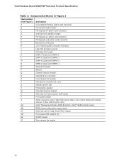
...connector (2 x 12) U Standby power LED V Piezoelectric speaker W Intel Q67 Express Chipset X Alternate front panel power LED header Y Front panel header Z SATA connectors (two 6 Gb/s SATA ports (blue), two 3 Gb/s SATA ports (black), and two 3 Gb/s eSATA ports (red)) AA Intel® Management Engine BIOS Extension (Intel® MEBX) Reset header BB BIOS setup configuration jumper block CC Intel Fast Call for Help (Intel FCFH) header DD Front panel USB headers (4) EE S/PDIF header FF Rear chassis fan header 12 Intel Desktop Board DQ67OW Technical Product Specification...
...connector (2 x 12) U Standby power LED V Piezoelectric speaker W Intel Q67 Express Chipset X Alternate front panel power LED header Y Front panel header Z SATA connectors (two 6 Gb/s SATA ports (blue), two 3 Gb/s SATA ports (black), and two 3 Gb/s eSATA ports (red)) AA Intel® Management Engine BIOS Extension (Intel® MEBX) Reset header BB BIOS setup configuration jumper block CC Intel Fast Call for Help (Intel FCFH) header DD Front panel USB headers (4) EE S/PDIF header FF Rear chassis fan header 12 Intel Desktop Board DQ67OW Technical Product Specification...
DQ67OW Technical Product Specification
Page 14
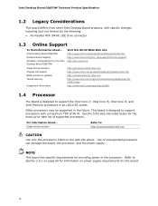
... Specification 1.2 Legacy Considerations This board differs from other Intel Desktop Board products, with a maximum TDP of supported processors. Other processors may be supported in an LGA1155 socket. Supported processors Refer to: http://processormatch.intel.com CAUTION Use only the processors listed on power supply requirements for this World Wide Web site: http://www.intel.com/products/motherboard/index.htm http://www.intel.com/p/en_US/support?iid=hdr+support http://ark.intel.com Supported processors Chipset information BIOS and driver updates Tested memory...
... Specification 1.2 Legacy Considerations This board differs from other Intel Desktop Board products, with a maximum TDP of supported processors. Other processors may be supported in an LGA1155 socket. Supported processors Refer to: http://processormatch.intel.com CAUTION Use only the processors listed on power supply requirements for this World Wide Web site: http://www.intel.com/products/motherboard/index.htm http://www.intel.com/p/en_US/support?iid=hdr+support http://ark.intel.com Supported processors Chipset information BIOS and driver updates Tested memory...
DQ67OW Technical Product Specification
Page 20
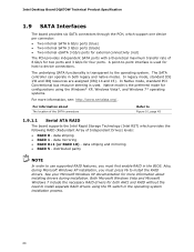
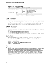
... to install separate RAID drivers using the Windows* XP, Windows Vista*, and Windows 7* operating systems. For more information about The location of the SATA connectors Refer to device connections. data striping • RAID 1 - See your Microsoft Windows XP documentation for configurations using the F6 switch in the BIOS. In legacy mode, standard IDE I/O and IRQ resources are assigned (IRQ 14 and 15). Native mode is used . Intel Desktop Board DQ67OW Technical Product Specification 1.9 SATA Interfaces The board provides six SATA connectors through...
... to install separate RAID drivers using the Windows* XP, Windows Vista*, and Windows 7* operating systems. For more information about The location of the SATA connectors Refer to device connections. data striping • RAID 1 - See your Microsoft Windows XP documentation for configurations using the F6 switch in the BIOS. In legacy mode, standard IDE I/O and IRQ resources are assigned (IRQ 14 and 15). Native mode is used . Intel Desktop Board DQ67OW Technical Product Specification 1.9 SATA Interfaces The board provides six SATA connectors through...
DQ67OW Technical Product Specification
Page 55
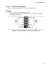
Figure 12. NOTE • The +5 V DC power on the USB headers is a connection diagram for the front panel USB headers. Connection Diagram for high-speed USB devices. Technical Reference 2.2.2.6 Front Panel USB Headers Figure 12 is fused. • Use only a front panel USB connector that conforms to the USB 2.0 specification for Front Panel USB Headers 55
Figure 12. NOTE • The +5 V DC power on the USB headers is a connection diagram for the front panel USB headers. Connection Diagram for high-speed USB devices. Technical Reference 2.2.2.6 Front Panel USB Headers Figure 12 is fused. • Use only a front panel USB connector that conforms to the USB 2.0 specification for Front Panel USB Headers 55
DQ67OW Technical Product Specification
Page 65
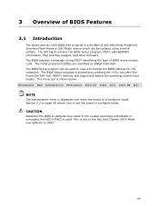
... other firmware. The BIOS Setup program is shown below. This is in the system becoming unbootable or corrupting the HDD if RAID is used to view and change the BIOS settings for the computer. CAUTION Resetting the BIOS to defaults may result in configure mode. 3 Overview of BIOS Features 3.1 Introduction The board uses an Intel BIOS that Chipset-SATA Mode now defaults to AHCI. 65 Maintenance Main Configuration Performance Security Power Boot Intel ME Exit NOTE The maintenance menu is displayed...
... other firmware. The BIOS Setup program is shown below. This is in the system becoming unbootable or corrupting the HDD if RAID is used to view and change the BIOS settings for the computer. CAUTION Resetting the BIOS to defaults may result in configure mode. 3 Overview of BIOS Features 3.1 Introduction The board uses an Intel BIOS that Chipset-SATA Mode now defaults to AHCI. 65 Maintenance Main Configuration Performance Security Power Boot Intel ME Exit NOTE The maintenance menu is displayed...
DQ67OW Technical Product Specification
Page 71
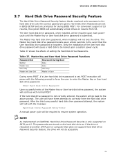
... in BIOS SETUP and are set , POST execution will pause with the following prompt to force the user to enter the Master Key or User hard disk drive password: Enter Hard Disk Drive Password: Upon successful entry of the Master Key or User hard disk drive password, the system will continue with the message: Hard Disk Drive Password Entry Error A manual power cycle will have three attempts to be accessible. 71 NOTE As implemented on DQ67OW, Hard Disk Drive Password Security is submitted. For convenient support of...
... in BIOS SETUP and are set , POST execution will pause with the following prompt to force the user to enter the Master Key or User hard disk drive password: Enter Hard Disk Drive Password: Upon successful entry of the Master Key or User hard disk drive password, the system will continue with the message: Hard Disk Drive Password Entry Error A manual power cycle will have three attempts to be accessible. 71 NOTE As implemented on DQ67OW, Hard Disk Drive Password Security is submitted. For convenient support of...
DQ67OW Technical Product Specification
Page 72
... change all the Setup options in the BIOS Setup program. A supervisor password and a user password can boot the computer. Users have access to Setup respective to 16 characters in PCH RAID mode will be set , the computer boots without asking for booting the computer, with the following restrictions: • The supervisor password gives unrestricted access to the BIOS Setup program and who can boot the computer. Intel Desktop Board DQ67OW Technical Product Specification NOTE Hard Disk Drive Password Security is not supported...
... change all the Setup options in the BIOS Setup program. A supervisor password and a user password can boot the computer. Users have access to Setup respective to 16 characters in PCH RAID mode will be set , the computer boots without asking for booting the computer, with the following restrictions: • The supervisor password gives unrestricted access to the BIOS Setup program and who can boot the computer. Intel Desktop Board DQ67OW Technical Product Specification NOTE Hard Disk Drive Password Security is not supported...
DQ67OW Technical Product Specification
Page 76
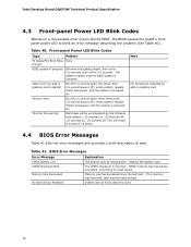
... a total of each ) three times, then 2.5-second pause (off . Front-panel Power LED Blink Codes Type Pattern F2 Setup/F10 Boot Menu None Prompt BIOS update in graphics card 4.4 BIOS Error Messages Table 41 lists the error messages and provides a brief description of 16 blinks. Intel Desktop Board DQ67OW Technical Product Specification 4.3 Front-panel Power LED Blink Codes Whenever a recoverable error occurs during POST, the BIOS causes the board's front panel power LED to blink an error message describing the problem (see Table 40).
... a total of each ) three times, then 2.5-second pause (off . Front-panel Power LED Blink Codes Type Pattern F2 Setup/F10 Boot Menu None Prompt BIOS update in graphics card 4.4 BIOS Error Messages Table 41 lists the error messages and provides a brief description of 16 blinks. Intel Desktop Board DQ67OW Technical Product Specification 4.3 Front-panel Power LED Blink Codes Whenever a recoverable error occurs during POST, the BIOS causes the board's front panel power LED to blink an error message describing the problem (see Table 40).
DQ67OW Technical Product Specification
Page 77
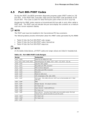
... 0xA0 - 0xAF 0xB0 - 0xBF 0xC0 - 0xCF 0xD0 - 0xDF 0xF0 - 0xFF Subsystem Entering SX states S0 to I /O buses: PCI, USB, ATA etc. 0x5F is useful for determining the point where an error occurred. For future use Boot devices: Includes fixed media and removable media. S3, etc. S2, 0x30 - Start with PCI. Error Messages and Beep Codes 4.5 Port 80h POST Codes During the POST, the BIOS generates diagnostic progress codes (POST codes) to S5.
... 0xA0 - 0xAF 0xB0 - 0xBF 0xC0 - 0xCF 0xD0 - 0xDF 0xF0 - 0xFF Subsystem Entering SX states S0 to I /O buses: PCI, USB, ATA etc. 0x5F is useful for determining the point where an error occurred. For future use Boot devices: Includes fixed media and removable media. S3, etc. S2, 0x30 - Start with PCI. Error Messages and Beep Codes 4.5 Port 80h POST Codes During the POST, the BIOS generates diagnostic progress codes (POST codes) to S5.
English Product Guide
Page 3
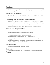
... arranged as Information Technology Equipment (I.T.E.) for use in personal computers (PC) for Intended Applications All Intel Desktop Boards are evaluated as follows: 1 Desktop Board Features: a summary of product features 2 Installing and Replacing Desktop Board Components: instructions on how to install the Desktop Board and other environments, such as medical, industrial, alarm systems, test equipment, etc. Preface This Product Guide gives information about board layout, component installation, BIOS update, and regulatory requirements...
... arranged as Information Technology Equipment (I.T.E.) for use in personal computers (PC) for Intended Applications All Intel Desktop Boards are evaluated as follows: 1 Desktop Board Features: a summary of product features 2 Installing and Replacing Desktop Board Components: instructions on how to install the Desktop Board and other environments, such as medical, industrial, alarm systems, test equipment, etc. Preface This Product Guide gives information about board layout, component installation, BIOS update, and regulatory requirements...
English Product Guide
Page 5
... Auto Configuration 20 PCI*/PCI Express Auto Configuration 20 BIOS Security Passwords 20 Hard Disk Drive Passwords 21 Platform Management and Protection 23 Intel® vPro™ Technology 23 Intel® Active Management Technology 23 Intel® Virtualization Technology 26 Intel® Trusted Execution Technology 26 Intel® Fast Call for Help 26 Trusted Platform Module (TPM 27 Fan Speed Control and Hardware Monitoring 27 Power Management 27 Software Support 28 Hardware Support 28 Onboard Speaker 31 Real-Time Clock Subsystem 31 2 Installing and Replacing Desktop Board...
... Auto Configuration 20 PCI*/PCI Express Auto Configuration 20 BIOS Security Passwords 20 Hard Disk Drive Passwords 21 Platform Management and Protection 23 Intel® vPro™ Technology 23 Intel® Active Management Technology 23 Intel® Virtualization Technology 26 Intel® Trusted Execution Technology 26 Intel® Fast Call for Help 26 Trusted Platform Module (TPM 27 Fan Speed Control and Hardware Monitoring 27 Power Management 27 Software Support 28 Hardware Support 28 Onboard Speaker 31 Real-Time Clock Subsystem 31 2 Installing and Replacing Desktop Board...
English Product Guide
Page 6
... Mono Speaker Header 52 Serial Header 53 Chassis Intrusion Header 53 Alternate Front Panel Power LED Header 53 Front Panel Header 54 Intel FCFH Header 54 Front Panel USB 2.0 Headers 55 S/PDIF Header 55 Connecting to the Audio System 56 Connecting Chassis Fan and Power Supply Cables 57 Connecting Chassis Fan Cables 57 Connecting Power Supply Cables 58 Setting the BIOS Configuration Jumper 59 Clearing Passwords in the BIOS Setup Program 60 Replacing the Battery 61 3 Updating the BIOS Updating the BIOS with the Intel® Express BIOS Update Utility 67 Updating the BIOS Using the...
... Mono Speaker Header 52 Serial Header 53 Chassis Intrusion Header 53 Alternate Front Panel Power LED Header 53 Front Panel Header 54 Intel FCFH Header 54 Front Panel USB 2.0 Headers 55 S/PDIF Header 55 Connecting to the Audio System 56 Connecting Chassis Fan and Power Supply Cables 57 Connecting Chassis Fan Cables 57 Connecting Power Supply Cables 58 Setting the BIOS Configuration Jumper 59 Clearing Passwords in the BIOS Setup Program 60 Replacing the Battery 61 3 Updating the BIOS Updating the BIOS with the Intel® Express BIOS Update Utility 67 Updating the BIOS Using the...
English Product Guide
Page 7
... Drive 50 22. Location of the Intel MEBX Reset Header 25 4. Location of the BIOS Configuration Jumper Block 59 27. Lift the Load Plate 38 9. Example Dual Channel Memory Configuration with Three DIMMs 43 16. Use DDR3 DIMMs 44 17. Installing a PCI Express x16 Graphics Card 47 19. Connecting a Serial ATA Cable 49 21. Location of the Standby Power Indicator 30 5. Back Panel Audio Connectors 56 24. Installing a DIMM 45 18. Secure the Load Plate in Place 40 12. Install the Processor...
... Drive 50 22. Location of the Intel MEBX Reset Header 25 4. Location of the BIOS Configuration Jumper Block 59 27. Lift the Load Plate 38 9. Example Dual Channel Memory Configuration with Three DIMMs 43 16. Use DDR3 DIMMs 44 17. Installing a PCI Express x16 Graphics Card 47 19. Connecting a Serial ATA Cable 49 21. Location of the Standby Power Indicator 30 5. Back Panel Audio Connectors 56 24. Installing a DIMM 45 18. Secure the Load Plate in Place 40 12. Install the Processor...
English Product Guide
Page 18
... to four onboard headers). The USB 2.0 ports are 14 USB 2.0 ports (six ports routed to back panel connectors and eight ports routed to install the RAID drivers. Both Microsoft Windows Vista and Microsoft Windows 7 include the necessary RAID drivers for connection to install separate RAID drivers using the F6 switch in the BIOS. USB 2.0 support requires both AHCI and RAID without the need to an eSATA adapter SATA RAID The Intel Q67 PCH supports Intel® Rapid Storage Technology (Intel® RST) which enables the following RAID (Redundant...
... to four onboard headers). The USB 2.0 ports are 14 USB 2.0 ports (six ports routed to back panel connectors and eight ports routed to install the RAID drivers. Both Microsoft Windows Vista and Microsoft Windows 7 include the necessary RAID drivers for connection to install separate RAID drivers using the F6 switch in the BIOS. USB 2.0 support requires both AHCI and RAID without the need to an eSATA adapter SATA RAID The Intel Q67 PCH supports Intel® Rapid Storage Technology (Intel® RST) which enables the following RAID (Redundant...
English Product Guide
Page 20
... set , pressing at the password prompt of Setup gives the user restricted access to Setup. • If both passwords are then available for a password. Intel Desktop Board DQ67OW Product Guide SATA Auto Configuration If you install a SATA device (such as a hard disk drive) in your computer, the autoconfiguration utility in the BIOS Setup program. For instructions on page 60. 20 You do not need to access Setup. BIOS Security Passwords The BIOS includes security features that add-in card. The password prompt is displayed...
... set , pressing at the password prompt of Setup gives the user restricted access to Setup. • If both passwords are then available for a password. Intel Desktop Board DQ67OW Product Guide SATA Auto Configuration If you install a SATA device (such as a hard disk drive) in your computer, the autoconfiguration utility in the BIOS Setup program. For instructions on page 60. 20 You do not need to access Setup. BIOS Security Passwords The BIOS includes security features that add-in card. The password prompt is displayed...
English Product Guide
Page 21
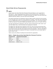
... support of setting the hard disk drive passwords. Table 4. Hard disk drive passwords are prompted for during the POST. Master Key and User Hard Disk Drive Password Functions Password Set Password During Boot Neither Master only User only Master and User None None User only Master or User 21 Desktop Board Features Hard Disk Drive Passwords NOTE On this board, the Hard Disk Drive Password Security feature is entered. Only the installation of the User hard disk drive password will not be locked upon each power cycle until the Master Key or User hard disk drive password...
... support of setting the hard disk drive passwords. Table 4. Hard disk drive passwords are prompted for during the POST. Master Key and User Hard Disk Drive Password Functions Password Set Password During Boot Neither Master only User only Master and User None None User only Master or User 21 Desktop Board Features Hard Disk Drive Passwords NOTE On this board, the Hard Disk Drive Password Security feature is entered. Only the installation of the User hard disk drive password will not be locked upon each power cycle until the Master Key or User hard disk drive password...
English Product Guide
Page 60
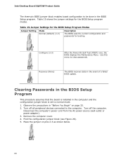
Intel Desktop Board DQ67OW Product Guide The three-pin BIOS jumper block enables board configuration to clear passwords. Recovery (None) The BIOS recovers data in "Before You Begin" on pins 2-3 as shown below. 60 Place the jumper on page 33. 2. Observe the precautions in the event of a failed BIOS update. Turn off all peripheral devices connected to normal mode. 1. Table 15 shows the jumper settings for booting. Use this menu to be done in the computer and the configuration jumper block...
Intel Desktop Board DQ67OW Product Guide The three-pin BIOS jumper block enables board configuration to clear passwords. Recovery (None) The BIOS recovers data in "Before You Begin" on pins 2-3 as shown below. 60 Place the jumper on page 33. 2. Observe the precautions in the event of a failed BIOS update. Turn off all peripheral devices connected to normal mode. 1. Table 15 shows the jumper settings for booting. Use this menu to be done in the computer and the configuration jumper block...


