
Product Guide
Page 3
... as Information Technology Equipment (I.T.E.) for use in personal computers (PC) for Intel® Desktop Board DH67CL. The suitability of this manual: CAUTION Cautions warn the user about board layout, component installation, BIOS update, and regulatory requirements for installation in this Product Guide are arranged as follows: 1 Desktop Board Features: a summary of product features 2 Installing and Replacing Desktop Board Components: instructions on how to update the BIOS A Error Messages and Indicators: information about BIOS error messages and beep codes B Regulatory...
... as Information Technology Equipment (I.T.E.) for use in personal computers (PC) for Intel® Desktop Board DH67CL. The suitability of this manual: CAUTION Cautions warn the user about board layout, component installation, BIOS update, and regulatory requirements for installation in this Product Guide are arranged as follows: 1 Desktop Board Features: a summary of product features 2 Installing and Replacing Desktop Board Components: instructions on how to update the BIOS A Error Messages and Indicators: information about BIOS error messages and beep codes B Regulatory...

Product Guide
Page 5
...15 Main Memory...15 Graphics Subsystem 16 Integrated Graphics 16 Intel® HD Graphics 16 High-Definition Multimedia Interface* (HDMI 16 Digital Visual Interface (DVI-I 16 VGA Displays 17 PCI Express* x16 Graphics 17 Audio Subsystem 17 LAN Subsystem 18 USB Support ...19 SATA Support...19 Expandability...19 Legacy I/O ...20 BIOS ...20 SATA Auto Configuration 20 PCI*/PCI Express Auto Configuration 20 Security Passwords 21 Hardware Management 21 Hardware Monitoring and Fan Speed Control 21 Fan Monitoring 21 Chassis Intrusion 22 Power Management 22 Software Support 22 ACPI 22...
...15 Main Memory...15 Graphics Subsystem 16 Integrated Graphics 16 Intel® HD Graphics 16 High-Definition Multimedia Interface* (HDMI 16 Digital Visual Interface (DVI-I 16 VGA Displays 17 PCI Express* x16 Graphics 17 Audio Subsystem 17 LAN Subsystem 18 USB Support ...19 SATA Support...19 Expandability...19 Legacy I/O ...20 BIOS ...20 SATA Auto Configuration 20 PCI*/PCI Express Auto Configuration 20 Security Passwords 21 Hardware Management 21 Hardware Monitoring and Fan Speed Control 21 Fan Monitoring 21 Chassis Intrusion 22 Power Management 22 Software Support 22 ACPI 22...
Product Guide
Page 6
... a PCI Express x16 Graphics Card 42 Connecting SATA Drives 43 Connecting to the Internal Headers 44 Front Panel Audio Header 45 Chassis Intrusion Header 45 Consumer IR (CIR) Headers 46 Alternate Front Panel Power LED Header 47 Front Panel Header 47 Front Panel USB 2.0 Headers 48 S/PDIF Header 48 Connecting to the Audio System 49 Connecting Chassis Fan and Power Supply Cables 50 Connecting a Chassis Fan 50 Connecting Power Supply Cables 51 Setting the BIOS Configuration Jumper 52 Clearing Passwords 53 Replacing the Battery 54 3 Updating the BIOS Updating the BIOS with the Intel...
... a PCI Express x16 Graphics Card 42 Connecting SATA Drives 43 Connecting to the Internal Headers 44 Front Panel Audio Header 45 Chassis Intrusion Header 45 Consumer IR (CIR) Headers 46 Alternate Front Panel Power LED Header 47 Front Panel Header 47 Front Panel USB 2.0 Headers 48 S/PDIF Header 48 Connecting to the Audio System 49 Connecting Chassis Fan and Power Supply Cables 50 Connecting a Chassis Fan 50 Connecting Power Supply Cables 51 Setting the BIOS Configuration Jumper 52 Clearing Passwords 53 Replacing the Battery 54 3 Updating the BIOS Updating the BIOS with the Intel...
Product Guide
Page 7
... 1. LAN Connector LEDs 18 3. Location of the Chassis Fan Header 50 23. Intel Desktop Board DH67CL Mounting Screw Hole Locations 30 6. Unlatch the Socket Lever 31 7. Install the Processor 33 10. Installing a DIMM 39 17. Removing a PCI Express x16 Graphics Card 42 19. Intel Desktop Board DH67CL China RoHS Material Self Declaration Table 72 vii Intel Desktop Board DH67CL Components 12 2. Lift the Load Plate 32 8. Connecting the Processor Fan Heat Sink Power Cable to the Processor Fan Header 35 12. Installing a PCI Express x16 Graphics Card 41 18. Connecting a SATA Drive...
... 1. LAN Connector LEDs 18 3. Location of the Chassis Fan Header 50 23. Intel Desktop Board DH67CL Mounting Screw Hole Locations 30 6. Unlatch the Socket Lever 31 7. Install the Processor 33 10. Installing a DIMM 39 17. Removing a PCI Express x16 Graphics Card 42 19. Intel Desktop Board DH67CL China RoHS Material Self Declaration Table 72 vii Intel Desktop Board DH67CL Components 12 2. Lift the Load Plate 32 8. Connecting the Processor Fan Heat Sink Power Cable to the Processor Fan Header 35 12. Installing a PCI Express x16 Graphics Card 41 18. Connecting a SATA Drive...

Product Guide
Page 10
...connector with integrated status LEDs • Intel® BIOS resident in an Serial Peripheral Interface (SPI) Flash device • Support for Advanced Configuration and Power Interface (ACPI), Plug and Play, and System Management BIOS (SMBIOS) • Unified Extensible Firmware Interface (UEFI) to support hard disk drives larger than 2 TB • BIOS support for Hyper Boot Instantly Available PC Technology • Support for PCI Local Bus Specification Revision 2.3 • Support for PCI Express Base Specification Revision 2.0 • Suspend to RAM support • Wake on PCI Express...
...connector with integrated status LEDs • Intel® BIOS resident in an Serial Peripheral Interface (SPI) Flash device • Support for Advanced Configuration and Power Interface (ACPI), Plug and Play, and System Management BIOS (SMBIOS) • Unified Extensible Firmware Interface (UEFI) to support hard disk drives larger than 2 TB • BIOS support for Hyper Boot Instantly Available PC Technology • Support for PCI Local Bus Specification Revision 2.3 • Support for PCI Express Base Specification Revision 2.0 • Suspend to RAM support • Wake on PCI Express...
Product Guide
Page 20
... Infrared (CIR) support • Serial IRQ interface compatible with serialized IRQ support for Conventional PCI bus systems • Intelligent power management, including a programmable wake-up event interface The BIOS Setup program provides configuration options for that add-in card. BIOS The BIOS provides the Power-On Self-Test (POST), the BIOS Setup program, and the PCI Express and SATA auto-configuration utilities. PCI*/PCI Express Auto Configuration If you install a SATA device (such as a hard drive) in your computer, the autoconfiguration utility in the BIOS automatically detects...
... Infrared (CIR) support • Serial IRQ interface compatible with serialized IRQ support for Conventional PCI bus systems • Intelligent power management, including a programmable wake-up event interface The BIOS Setup program provides configuration options for that add-in card. BIOS The BIOS provides the Power-On Self-Test (POST), the BIOS Setup program, and the PCI Express and SATA auto-configuration utilities. PCI*/PCI Express Auto Configuration If you install a SATA device (such as a hard drive) in your computer, the autoconfiguration utility in the BIOS automatically detects...

Product Guide
Page 22
... location of the power connectors. 22 Intel Desktop Board DH67CL Product Guide Chassis Intrusion The board supports a chassis security feature that provides full ACPI support. See Figure 1 for the location of the chassis intrusion header. Hardware Support Power Connectors ATX12V-compliant power supplies can be set by using the Last Power State feature in before power was in the BIOS Setup program's Boot menu. The security feature uses a mechanical switch on the chassis that can turn off ). The use of a computer. When resuming from CIR Software Support ACPI ACPI...
... location of the power connectors. 22 Intel Desktop Board DH67CL Product Guide Chassis Intrusion The board supports a chassis security feature that provides full ACPI support. See Figure 1 for the location of the chassis intrusion header. Hardware Support Power Connectors ATX12V-compliant power supplies can be set by using the Last Power State feature in before power was in the BIOS Setup program's Boot menu. The security feature uses a mechanical switch on the chassis that can turn off ). The use of a computer. When resuming from CIR Software Support ACPI ACPI...
Product Guide
Page 25
... not plugged into a wall socket, the battery has an estimated life of the board's beep codes. Go to page 54 for instructions on a PCI Express bus add-in CMOS RAM (for a description of three years. PCI Express WAKE# Signal Wake-up Support When the WAKE# signal on how to Appendix A for example, the date and time) might not be notified during the Power-On Self-Test (POST). Refer to replace the battery...
... not plugged into a wall socket, the battery has an estimated life of the board's beep codes. Go to page 54 for instructions on a PCI Express bus add-in CMOS RAM (for a description of three years. PCI Express WAKE# Signal Wake-up Support When the WAKE# signal on how to Appendix A for example, the date and time) might not be notified during the Power-On Self-Test (POST). Refer to replace the battery...

Product Guide
Page 27
... Desktop Board Components This chapter tells you how to: • Install the I/O shield • Install and remove the Desktop Board • Install and remove a processor • Install and remove memory • Install and remove a PCI Express x16 card • Connect SATA drives • Connect to the internal headers • Connect to the audio system • Connect chassis fan and power supply cables • Set the BIOS configuration jumper • Clear passwords • Replace the battery Before You Begin CAUTION The procedures in this chapter only at an ESD workstation using...
... Desktop Board Components This chapter tells you how to: • Install the I/O shield • Install and remove the Desktop Board • Install and remove a processor • Install and remove memory • Install and remove a PCI Express x16 card • Connect SATA drives • Connect to the internal headers • Connect to the audio system • Connect chassis fan and power supply cables • Set the BIOS configuration jumper • Clear passwords • Replace the battery Before You Begin CAUTION The procedures in this chapter only at an ESD workstation using...
Product Guide
Page 53
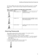
... jumper on page 27. 2. Jumper Settings for the BIOS Setup Program Modes Jumper Setting Mode Normal (default) (1-2) Description The BIOS uses the current configuration and passwords for the BIOS Setup program modes. Clearing Passwords This procedure assumes that the board is set to the computer. Turn off the computer. Table 14. Installing and Replacing Desktop Board Components The three-pin BIOS jumper block enables board configuration to clear passwords. Use this menu to be done in the event of a failed BIOS update. Turn off all peripheral devices connected...
... jumper on page 27. 2. Jumper Settings for the BIOS Setup Program Modes Jumper Setting Mode Normal (default) (1-2) Description The BIOS uses the current configuration and passwords for the BIOS Setup program modes. Clearing Passwords This procedure assumes that the board is set to the computer. Turn off the computer. Table 14. Installing and Replacing Desktop Board Components The three-pin BIOS jumper block enables board configuration to clear passwords. Use this menu to be done in the event of a failed BIOS update. Turn off all peripheral devices connected...
Product Guide
Page 61
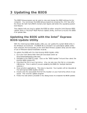
... file from the location on the "BIOS Update" link and then select the Express BIOS Update file. 3. 3 Updating the BIOS The BIOS Setup program can be rebooted at http://downloadcenter.intel.com/ 2. This chapter tells you are updating the BIOS for the computer. Click on your hard drive. (You can also save this file to a removable USB device. Download the file to your hard drive where it was saved. This step is included in the Windows...
... file from the location on the "BIOS Update" link and then select the Express BIOS Update file. 3. 3 Updating the BIOS The BIOS Setup program can be rebooted at http://downloadcenter.intel.com/ 2. This chapter tells you are updating the BIOS for the computer. Click on your hard drive. (You can also save this file to a removable USB device. Download the file to your hard drive where it was saved. This step is included in the Windows...
Product Specification
Page 9
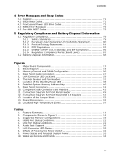
... Figures 1. Memory Channel and DIMM Configuration 20 4. LAN Connector LED Locations 29 6. Board Dimensions 54 15. Contents 4 Error Messages and Beep Codes 4.1 Speaker 71 4.2 BIOS Beep Codes 71 4.3 Front-panel Power LED Blink Codes 72 4.4 BIOS Error Messages 72 4.5 Port 80h POST Codes 73 5 Regulatory Compliance and Battery Disposal Information 5.1 Regulatory Compliance 79 5.1.1 Safety Standards 79 5.1.2 European Union Declaration of Pressing the Power Switch 32 9. Back Panel Audio Connectors 27 5. Thermal Sensors and Fan Headers 31 7. Component-side Connectors and Headers 43...
... Figures 1. Memory Channel and DIMM Configuration 20 4. LAN Connector LED Locations 29 6. Board Dimensions 54 15. Contents 4 Error Messages and Beep Codes 4.1 Speaker 71 4.2 BIOS Beep Codes 71 4.3 Front-panel Power LED Blink Codes 72 4.4 BIOS Error Messages 72 4.5 Port 80h POST Codes 73 5 Regulatory Compliance and Battery Disposal Information 5.1 Regulatory Compliance 79 5.1.1 Safety Standards 79 5.1.2 European Union Declaration of Pressing the Power Switch 32 9. Back Panel Audio Connectors 27 5. Thermal Sensors and Fan Headers 31 7. Component-side Connectors and Headers 43...
Product Specification
Page 10
.... Back Panel CIR Emitter (Output) Header 46 21. Processor Core Power Connector 48 23. Alternate Front Panel Power/Sleep LED Header 50 28. BIOS Setup Configuration Jumper Settings 53 29. Tcontrol Values for a One-Color Power LED 50 26. Front-panel Power LED Blink Codes 72 41. Typical Port 80h POST Sequence 78 45. Front Panel Audio Header for AC '97 Audio 45 15. Front Panel Audio Header for Intel HD Audio 45 14. Environmental Specifications 59 34. Boot Device Menu Options 66 38. BIOS Error Messages 72 42. BIOS Beep Codes 71...
.... Back Panel CIR Emitter (Output) Header 46 21. Processor Core Power Connector 48 23. Alternate Front Panel Power/Sleep LED Header 50 28. BIOS Setup Configuration Jumper Settings 53 29. Tcontrol Values for a One-Color Power LED 50 26. Front-panel Power LED Blink Codes 72 41. Typical Port 80h POST Sequence 78 45. Front Panel Audio Header for AC '97 Audio 45 15. Front Panel Audio Header for Intel HD Audio 45 14. Environmental Specifications 59 34. Boot Device Menu Options 66 38. BIOS Error Messages 72 42. BIOS Beep Codes 71...
Product Specification
Page 24
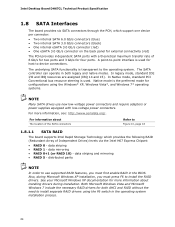
...; RAID 5 - In Native mode, standard PCI Conventional bus resource steering is the preferred mode for configurations using the F6 switch in the operating system installation process. 24 For more information about The location of the SATA connectors Refer to use new low-voltage power connectors and require adapters or power supplies equipped with a theoretical maximum transfer rate of Independent Drives) levels via the Intel H67 Express Chipset: • RAID 0 - data mirroring • RAID 0+1 (or RAID...
...; RAID 5 - In Native mode, standard PCI Conventional bus resource steering is the preferred mode for configurations using the F6 switch in the operating system installation process. 24 For more information about The location of the SATA connectors Refer to use new low-voltage power connectors and require adapters or power supplies equipped with a theoretical maximum transfer rate of Independent Drives) levels via the Intel H67 Express Chipset: • RAID 0 - data mirroring • RAID 0+1 (or RAID...

Product Specification
Page 28
Intel Desktop Board DH67CL Technical Product Specification 1.12 LAN Subsystem The LAN subsystem consists of the following: • Intel 82579V Gigabit Ethernet Controller (10/100/1000 Mbits/s) • Intel P67 Express Chipset • RJ-45 LAN connector with integrated status LEDs Additional features of the LAN subsystem include: • CSMA/CD protocol engine • LAN connect interface between the PCH and the LAN controller • PCI Conventional bus power management ⎯ ACPI technology support ⎯ LAN wake capabilities •...
Intel Desktop Board DH67CL Technical Product Specification 1.12 LAN Subsystem The LAN subsystem consists of the following: • Intel 82579V Gigabit Ethernet Controller (10/100/1000 Mbits/s) • Intel P67 Express Chipset • RJ-45 LAN connector with integrated status LEDs Additional features of the LAN subsystem include: • CSMA/CD protocol engine • LAN connect interface between the PCH and the LAN controller • PCI Conventional bus power management ⎯ ACPI technology support ⎯ LAN wake capabilities •...

Product Specification
Page 51
.... • Use only a front panel USB connector that can decode the port and display the contents on the USB headers is left at port 80h. Technical Reference 2.2.2.6 Front Panel USB 2.0 Headers Figure 12 is a connection diagram for determining the point where an error occurred. Figure 12. Connection Diagram for high-speed USB devices. Table 28. Displaying the POST codes requires a POST card that conforms to the USB 2.0 specification for Front Panel USB 2.0 Headers 2.2.2.7 Low Pin Count (LPC) Debug header During the POST, the BIOS generates...
.... • Use only a front panel USB connector that can decode the port and display the contents on the USB headers is left at port 80h. Technical Reference 2.2.2.6 Front Panel USB 2.0 Headers Figure 12 is a connection diagram for determining the point where an error occurred. Figure 12. Connection Diagram for high-speed USB devices. Table 28. Displaying the POST codes requires a POST card that conforms to the USB 2.0 specification for Front Panel USB 2.0 Headers 2.2.2.7 Low Pin Count (LPC) Debug header During the POST, the BIOS generates...

Product Specification
Page 61
... the BIOS Setup configuration jumper is set to configure mode and the computer is powered-up, the BIOS compares the CPU version and the microcode version in configure mode. The BIOS Setup program can be used to put the board in configure mode. 61 Maintenance Main Configuration Performance Security Power Boot Exit NOTE The maintenance menu is displayed only when the board is stored in the Serial Peripheral Interface Flash Memory (SPI Flash) and can be updated using a disk-based program. The BIOS Setup program is...
... the BIOS Setup configuration jumper is set to configure mode and the computer is powered-up, the BIOS compares the CPU version and the microcode version in configure mode. The BIOS Setup program can be used to put the board in configure mode. 61 Maintenance Main Configuration Performance Security Power Boot Exit NOTE The maintenance menu is displayed only when the board is stored in the Serial Peripheral Interface Flash Memory (SPI Flash) and can be updated using a disk-based program. The BIOS Setup program is...
Product Specification
Page 62
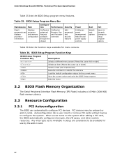
... Displays processor and memory configuration Configures advanced features available through the chipset Configures Memory, Bus and Processor overrides Security Sets passwords and security features Power Configures power management features and power supply controls Boot Selects boot options Exit Saves or discards changes to configure the system. Intel Desktop Board DH67CL Technical Product Specification Table 35 lists the BIOS Setup program menu features. BIOS Setup Program Function Keys BIOS Setup Program Function Key Description or or Selects a different menu screen...
... Displays processor and memory configuration Configures advanced features available through the chipset Configures Memory, Bus and Processor overrides Security Sets passwords and security features Power Configures power management features and power supply controls Boot Selects boot options Exit Saves or discards changes to configure the system. Intel Desktop Board DH67CL Technical Product Specification Table 35 lists the BIOS Setup program menu features. BIOS Setup Program Function Keys BIOS Setup Program Function Key Description or or Selects a different menu screen...
Product Specification
Page 73
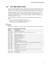
... use Input devices: Keyboard/Mouse. Start with the Low Pin Count (LPC) Debug header. For future use Boot Devices: Includes fixed media and removable media. Not that can decode the port and display the contents on a medium such as a seven-segment display. Error Messages and Beep Codes 4.5 Port 80h POST Codes During the POST, the BIOS generates diagnostic progress codes (POST codes) to I /O Buses: PCI, USB, ATA etc. 0x5F is left at this point. Displaying the POST codes requires a POST card...
... use Input devices: Keyboard/Mouse. Start with the Low Pin Count (LPC) Debug header. For future use Boot Devices: Includes fixed media and removable media. Not that can decode the port and display the contents on a medium such as a seven-segment display. Error Messages and Beep Codes 4.5 Port 80h POST Codes During the POST, the BIOS generates diagnostic progress codes (POST codes) to I /O Buses: PCI, USB, ATA etc. 0x5F is left at this point. Displaying the POST codes requires a POST card...
DH67CL Specification Update
Page 6
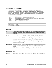
... the Specification Changes, Errata, Specification Clarifications, or Documentation Changes that apply to the Intel® Desktop Board DH67CL. Fixed: This erratum has been previously fixed. Implication: PCI cards utilizing a PCI Express to PCI bridge chip will not be implemented. No Fix: There are used in the PCI card not being recognized by BIOS and not functioning. PCI cards that utilize a PCI Express* to PCI bridge component may not work with Intel® Desktop Boards based on the affected Intel Desktop boards. Shaded...
... the Specification Changes, Errata, Specification Clarifications, or Documentation Changes that apply to the Intel® Desktop Board DH67CL. Fixed: This erratum has been previously fixed. Implication: PCI cards utilizing a PCI Express to PCI bridge chip will not be implemented. No Fix: There are used in the PCI card not being recognized by BIOS and not functioning. PCI cards that utilize a PCI Express* to PCI bridge component may not work with Intel® Desktop Boards based on the affected Intel Desktop boards. Shaded...


