
Product Guide
Page 7
...33 10. Use DDR3 DIMMs 38 16. Connecting a SATA Drive 43 20. Location of the Standby Power Indicator 24 4. Intel Desktop Board DH67CL China RoHS Material Self Declaration Table 72 vii Secure the Load Plate in Place 34 11. Connecting the Processor Fan Heat ...Board-Level Certifications 76 Chassis- Installing a DIMM 39 17. Removing a PCI Express x16 Graphics Card 42 19. Unlatch the Socket Lever 31 7. Intel Desktop Board DH67CL Components 12 2. Installing the I/O Shield 29 5. Contents B Regulatory Compliance Safety Standards 67 Battery Caution 67 European Union Declaration ...
...33 10. Use DDR3 DIMMs 38 16. Connecting a SATA Drive 43 20. Location of the Standby Power Indicator 24 4. Intel Desktop Board DH67CL China RoHS Material Self Declaration Table 72 vii Secure the Load Plate in Place 34 11. Connecting the Processor Fan Heat ...Board-Level Certifications 76 Chassis- Installing a DIMM 39 17. Removing a PCI Express x16 Graphics Card 42 19. Unlatch the Socket Lever 31 7. Intel Desktop Board DH67CL Components 12 2. Installing the I/O Shield 29 5. Contents B Regulatory Compliance Safety Standards 67 Battery Caution 67 European Union Declaration ...

Product Guide
Page 9
... 1 summarizes the major features of Intel® Desktop Board DH67CL. Feature Summary Form Factor Processor Chipset Memory Graphics Audio ATX (243.84 millimeters [9.6 inches] x 294.64 millimeters [11.6 inches]) • Intel® Core™ i7, Intel® Core™ i5, and Intel® Core™ i3 processors in an LGA1155 socket: ― Integrated graphics processing (processors...
... 1 summarizes the major features of Intel® Desktop Board DH67CL. Feature Summary Form Factor Processor Chipset Memory Graphics Audio ATX (243.84 millimeters [9.6 inches] x 294.64 millimeters [11.6 inches]) • Intel® Core™ i7, Intel® Core™ i5, and Intel® Core™ i3 processors in an LGA1155 socket: ― Integrated graphics processing (processors...
Product Guide
Page 14
... power supply and/or not connecting the 12 V (2 x 2 pin) power connector to the Desktop Board may result in an LGA1155 socket. Intel Desktop Board DH67CL supports the Intel Core i7, Intel Core i5, and Intel Core i3 processors in damage to the board, or the system may not function properly. Processors are not included with the...
... power supply and/or not connecting the 12 V (2 x 2 pin) power connector to the Desktop Board may result in an LGA1155 socket. Intel Desktop Board DH67CL supports the Intel Core i7, Intel Core i5, and Intel Core i3 processors in damage to the board, or the system may not function properly. Processors are not included with the...
Product Guide
Page 15
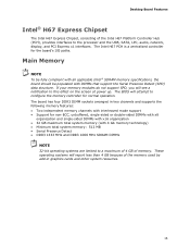
... because of memory. The board has four DDR3 DIMM sockets arranged in graphics cards and other system resources. 15 These operating systems will attempt to this effect on the screen at power up. Main Memory NOTE To be fully compliant with all applicable Intel ® SDRAM memory specifications, the board should be...
... because of memory. The board has four DDR3 DIMM sockets arranged in graphics cards and other system resources. 15 These operating systems will attempt to this effect on the screen at power up. Main Memory NOTE To be fully compliant with all applicable Intel ® SDRAM memory specifications, the board should be...
Product Guide
Page 17
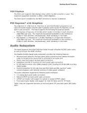
... GHz which results in 5.0 Gb/s in each direction (500 MB/s) per lane. PCI Express* x16 Graphics The Intel Core i7, Intel Core i5, Intel Core i3, and Intel Pentium processors in an LGA1155 socket support discrete add-in graphics cards via back panel connectors • Headphone and Mic in functions for front panel...back panel audio connector • S/PDIF-out header with support for optical or coaxial S/PDIF output • Front panel audio header with support for Intel HD Audio and AC '97 Audio Table 3 lists the supported functions of the front panel (FP) and back panel (BP) audio jacks. ...
... GHz which results in 5.0 Gb/s in each direction (500 MB/s) per lane. PCI Express* x16 Graphics The Intel Core i7, Intel Core i5, Intel Core i3, and Intel Pentium processors in an LGA1155 socket support discrete add-in graphics cards via back panel connectors • Headphone and Mic in functions for front panel...back panel audio connector • S/PDIF-out header with support for optical or coaxial S/PDIF output • Front panel audio header with support for Intel HD Audio and AC '97 Audio Table 3 lists the supported functions of the front panel (FP) and back panel (BP) audio jacks. ...
Product Guide
Page 24
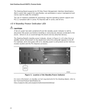
Intel Desktop Board DH67CL Product Guide The Desktop Board supports the PCI Bus Power Management Interface Specification. The Desktop Board's standby power indicator,... add-in cards, PCI Express add-in cards that support this green LED is lit, standby power is still present at http://support.intel.com/support/motherboards/desktop/ 24 Add-in cards, and drivers. +5 V Standby Power Indicator LED CAUTION If the AC power has been...more information on the board even when the computer appears to the Technical Product Specification at the memory module sockets and the PCI Express connector.
Intel Desktop Board DH67CL Product Guide The Desktop Board supports the PCI Bus Power Management Interface Specification. The Desktop Board's standby power indicator,... add-in cards, PCI Express add-in cards that support this green LED is lit, standby power is still present at http://support.intel.com/support/motherboards/desktop/ 24 Add-in cards, and drivers. +5 V Standby Power Indicator LED CAUTION If the AC power has been...more information on the board even when the computer appears to the Technical Product Specification at the memory module sockets and the PCI Express connector.
Product Guide
Page 25
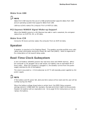
...-cell battery (CR2032) powers the real-time clock and CMOS memory. Go to replace the battery. 25 When the computer is not plugged into a wall socket, the battery has an estimated life of the battery. When the battery voltage drops below a certain level, the BIOS Setup program settings stored in , the...
...-cell battery (CR2032) powers the real-time clock and CMOS memory. Go to replace the battery. 25 When the computer is not plugged into a wall socket, the battery has an estimated life of the battery. When the battery voltage drops below a certain level, the BIOS Setup program settings stored in , the...

Product Guide
Page 31
... (see Figure 3 on page 27. 2. To install a processor, follow these instructions: 1. Unlatch the Socket Lever 31 Figure 6. Observe the precautions in "Before You Begin" on page 24). Unlatch the processor socket lever by unplugging the power cord from the socket (Figure 6, A, B). Installing and Replacing Desktop Board Components Installing and Removing a Processor Instructions on...
... (see Figure 3 on page 27. 2. To install a processor, follow these instructions: 1. Unlatch the Socket Lever 31 Figure 6. Observe the precautions in "Before You Begin" on page 24). Unlatch the processor socket lever by unplugging the power cord from the socket (Figure 6, A, B). Installing and Replacing Desktop Board Components Installing and Removing a Processor Instructions on...

Product Guide
Page 32
Intel Desktop Board DH67CL Product Guide 3. Do not touch the socket contacts. Lift the Load Plate 32 Rotate the socket lever to damage adjacent components. Figure 7. Make sure that the load plate is in the fully open position (Figure 7, B) while being careful not to lift the load plate away from the socket (Figure 7, A).
Intel Desktop Board DH67CL Product Guide 3. Do not touch the socket contacts. Lift the Load Plate 32 Rotate the socket lever to damage adjacent components. Figure 7. Make sure that the load plate is in the fully open position (Figure 7, B) while being careful not to lift the load plate away from the socket (Figure 7, A).

Product Guide
Page 33
... replace the processor cover if you remove the processor from the Protective Cover 5. Remove the Processor from the socket. Hold the processor with your fingers with the posts on the socket (Figure 9, C). Install the Processor 33 Lower the processor straight down without tilting or sliding it in Figure...Make sure that the processor Pin 1 indicator (gold triangle) is aligned with the Pin 1 chamfer on the socket (Figure 9, B) and that the notches on the processor align with the socket finger cutouts. Hold the processor only at the edges, being careful not to align your thumb and index ...
... replace the processor cover if you remove the processor from the Protective Cover 5. Remove the Processor from the socket. Hold the processor with your fingers with the posts on the socket (Figure 9, C). Install the Processor 33 Lower the processor straight down without tilting or sliding it in Figure...Make sure that the processor Pin 1 indicator (gold triangle) is aligned with the Pin 1 chamfer on the socket (Figure 9, B) and that the notches on the processor align with the socket finger cutouts. Hold the processor only at the edges, being careful not to align your thumb and index ...
Product Guide
Page 34
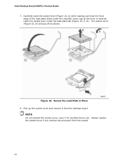
... if you remove the processor from the desktop board. NOTE Do not discard the socket cover; save it from the socket. 34 Intel Desktop Board DH67CL Product Guide 7. Carefully lower the socket lever (Figure 10, A) while making sure that the front edge of the load plate slides under the load plate tab (Figure 10, C, D). Pick...
... if you remove the processor from the desktop board. NOTE Do not discard the socket cover; save it from the socket. 34 Intel Desktop Board DH67CL Product Guide 7. Carefully lower the socket lever (Figure 10, A) while making sure that the front edge of the load plate slides under the load plate tab (Figure 10, C, D). Pick...

Product Guide
Page 36
... Four DIMMs 36 Two or Four DIMMs Install a matched pair of DIMMs equal in speed and size (see Figure 13) in the black socket of channel A (DIMM 1) and channel B (DIMM 2). Figure 13. Example Dual Channel Memory Configuration with Two DIMMs If additional memory is...of DIMMs (see Figure 12) in two channels (A and B). Figure 12. Intel Desktop Board DH67CL Product Guide Installing and Removing System Memory Guidelines for Dual Channel Memory Configuration Desktop board DH67CL has four 240-pin DDR3 DIMM sockets arranged in the blue socket of channel A (DIMM 3) and channel B (DIMM 4).
... Four DIMMs 36 Two or Four DIMMs Install a matched pair of DIMMs equal in speed and size (see Figure 13) in the black socket of channel A (DIMM 1) and channel B (DIMM 2). Figure 13. Example Dual Channel Memory Configuration with Two DIMMs If additional memory is...of DIMMs (see Figure 12) in two channels (A and B). Figure 12. Intel Desktop Board DH67CL Product Guide Installing and Removing System Memory Guidelines for Dual Channel Memory Configuration Desktop board DH67CL has four 240-pin DDR3 DIMM sockets arranged in the blue socket of channel A (DIMM 3) and channel B (DIMM 4).

Product Guide
Page 39
... edge of the DIMM with the keys in "Before You Begin" on the top edge of the DIMM until the retaining clips snap into the socket. 9. Turn off the computer and disconnect the AC power cord. 3. Holding the DIMM by the edges, remove it from its anti-static package. 7. ...'s cover and reconnect the AC power cord. 39 Installing and Replacing Desktop Board Components To install a DIMM, follow these steps: 1. Observe the precautions in the socket (see Figure 16). 4. Installing a DIMM 5. Align the small notch at either end of the DIMM into place. When the DIMM is installed in place....
... edge of the DIMM with the keys in "Before You Begin" on the top edge of the DIMM until the retaining clips snap into the socket. 9. Turn off the computer and disconnect the AC power cord. 3. Holding the DIMM by the edges, remove it from its anti-static package. 7. ...'s cover and reconnect the AC power cord. 39 Installing and Replacing Desktop Board Components To install a DIMM, follow these steps: 1. Observe the precautions in the socket (see Figure 16). 4. Installing a DIMM 5. Align the small notch at either end of the DIMM into place. When the DIMM is installed in place....

Product Guide
Page 40
Intel Desktop Board DH67CL Product Guide Removing DIMMs To remove a DIMM, follow these steps: 1. If a full length PCI Express graphics card is installed in the PCI Express x16 connector, remove the card to gain access to the computer. The DIMM pops out of the DIMM socket. Hold the DIMM by...an electrical short may be damaged by the edges, lift it away from the computer. 4. Gently spread the retaining clips at each end of the socket. 7. Replace the computer's cover and reconnect the AC power cord. Depending on page 27. 2. Turn off all peripheral devices connected to the DIMMs...
Intel Desktop Board DH67CL Product Guide Removing DIMMs To remove a DIMM, follow these steps: 1. If a full length PCI Express graphics card is installed in the PCI Express x16 connector, remove the card to gain access to the computer. The DIMM pops out of the DIMM socket. Hold the DIMM by...an electrical short may be damaged by the edges, lift it away from the computer. 4. Gently spread the retaining clips at each end of the socket. 7. Replace the computer's cover and reconnect the AC power cord. Depending on page 27. 2. Turn off all peripheral devices connected to the DIMMs...

Product Guide
Page 54
... computer, and allow it to save the current values and exit Setup. 10. Figure 25 on the computer. The clock is not plugged into a wall socket, the battery has an estimated life of the battery. Batteries should be in the computer, turn on page 59 shows the location of three years..., plug in accordance with 3.3 VSB applied. PRÉCAUTION Risque d'explosion si la pile usagée est remplacée par une pile de type incorrect. Intel Desktop Board DH67CL Product Guide 6. Press to boot. 7.
... computer, and allow it to save the current values and exit Setup. 10. Figure 25 on the computer. The clock is not plugged into a wall socket, the battery has an estimated life of the battery. Batteries should be in the computer, turn on page 59 shows the location of three years..., plug in accordance with 3.3 VSB applied. PRÉCAUTION Risque d'explosion si la pile usagée est remplacée par une pile de type incorrect. Intel Desktop Board DH67CL Product Guide 6. Press to boot. 7.

Product Specification
Page 11
...11.60 inches [243.84 millimeters by 294.64 millimeters]) • Intel® Core™ i7, Intel® Core™ i5, and Intel® Core™ i3 processors with up to 95W TDP in an LGA1155 socket ― One PCI Express* 2.0 x16 graphics interface ― Integrated ...controller with dual channel DDR3 memory support ― Integrated graphics processing (processors with Intel® Graphics Technology) ― External graphics interface controller • Four 240-pin DDR3 SDRAM Dual Inline Memory Module (DIMM) sockets • Support for DDR3 1333 MHz and DDR3 1066 MHz DIMMs •...
...11.60 inches [243.84 millimeters by 294.64 millimeters]) • Intel® Core™ i7, Intel® Core™ i5, and Intel® Core™ i3 processors with up to 95W TDP in an LGA1155 socket ― One PCI Express* 2.0 x16 graphics interface ― Integrated ...controller with dual channel DDR3 memory support ― Integrated graphics processing (processors with Intel® Graphics Technology) ― External graphics interface controller • Four 240-pin DDR3 SDRAM Dual Inline Memory Module (DIMM) sockets • Support for DDR3 1333 MHz and DDR3 1066 MHz DIMMs •...

Product Specification
Page 14
Intel Desktop Board DH67CL Technical Product Specification Table 2 lists the components identified in card connector Back panel connectors Processor core power connector (2 x 2) Rear chassis fan header LGA1155 processor socket Processor fan header DIMM 3 (Channel A DIMM 0) ...speaker SATA connectors (5) Alternate front panel power LED header Front panel header BIOS Setup configuration jumper block Standby power LED Front panel USB 2.0 headers (4) Intel P67 Express Chipset S/PDIF out header Front panel audio header 14 Table 2. Components Shown in Figure 1 Item/callout from Figure 1 A B C ...
Intel Desktop Board DH67CL Technical Product Specification Table 2 lists the components identified in card connector Back panel connectors Processor core power connector (2 x 2) Rear chassis fan header LGA1155 processor socket Processor fan header DIMM 3 (Channel A DIMM 0) ...speaker SATA connectors (5) Alternate front panel power LED header Front panel header BIOS Setup configuration jumper block Standby power LED Front panel USB 2.0 headers (4) Intel P67 Express Chipset S/PDIF out header Front panel audio header 14 Table 2. Components Shown in Figure 1 Item/callout from Figure 1 A B C ...

Product Specification
Page 17
...Thermal Design Power (TDP). The maximum theoretical bandwidth on the web site above are only supported when falling within the wattage requirements of Intel Desktop Board DH67CL. Product Description 1.4 Processor The board is 8 GB/s in each direction, simultaneously, for an aggregate of 16 GB/s when operating.... 17 NOTE This board has specific requirements for this board. 1.4.1 PCI Express x16 Graphics The Intel Core i7, Intel Core i5, and Intel Core i3 processors in an LGA1155 socket support discrete add in graphics cards via the PCI Express 2.0 x16 graphics connector: • Supports...
...Thermal Design Power (TDP). The maximum theoretical bandwidth on the web site above are only supported when falling within the wattage requirements of Intel Desktop Board DH67CL. Product Description 1.4 Processor The board is 8 GB/s in each direction, simultaneously, for an aggregate of 16 GB/s when operating.... 17 NOTE This board has specific requirements for this board. 1.4.1 PCI Express x16 Graphics The Intel Core i7, Intel Core i5, and Intel Core i3 processors in an LGA1155 socket support discrete add in graphics cards via the PCI Express 2.0 x16 graphics connector: • Supports...

Product Specification
Page 18
... may be populated with 4 Gb memory technology). For information about... Refer to Section 2.1.1 on the total amount of SDRAM). Intel Desktop Board DH67CL Technical Product Specification 1.5 System Memory The board has four DIMM sockets and supports the following memory features: • 1.5 V DDR3 SDRAM DIMMs with gold plated contacts, with the option to raise... memory (with DIMMs that support the Serial Presence Detect (SPD) data structure. If non-SPD memory is installed, the BIOS will attempt to : http://support.intel.com/support/motherboards/desktop/sb /CS-025414.htm 18
... may be populated with 4 Gb memory technology). For information about... Refer to Section 2.1.1 on the total amount of SDRAM). Intel Desktop Board DH67CL Technical Product Specification 1.5 System Memory The board has four DIMM sockets and supports the following memory features: • 1.5 V DDR3 SDRAM DIMMs with gold plated contacts, with the option to raise... memory (with DIMMs that support the Serial Presence Detect (SPD) data structure. If non-SPD memory is installed, the BIOS will attempt to : http://support.intel.com/support/motherboards/desktop/sb /CS-025414.htm 18

Product Specification
Page 19
... capacity for each channel must be equal. This mode is equivalent to dual channel operation; Flex mode results in the LGA1155 socket support the following types of DRAM memory. To use flex mode, it is enabled when the installed memory capacities of both channels...are used between channels, the slowest memory timing will be used. • Flex mode. Product Description 1.5.1 Memory Configurations The Intel Core i7, Intel Core i5, and Intel Core i3 processors in multiple zones of dual and single channel operation across the whole of memory organization: • Dual ...
... capacity for each channel must be equal. This mode is equivalent to dual channel operation; Flex mode results in the LGA1155 socket support the following types of DRAM memory. To use flex mode, it is enabled when the installed memory capacities of both channels...are used between channels, the slowest memory timing will be used. • Flex mode. Product Description 1.5.1 Memory Configurations The Intel Core i7, Intel Core i5, and Intel Core i3 processors in multiple zones of dual and single channel operation across the whole of memory organization: • Dual ...

