
Product Guide
Page 6
Intel Desktop Board DH67CL Product Guide Installing the I/O Shield 29 Installing and Removing the Desktop Board 30 Installing and Removing a Processor 31 Installing a Processor 31 Installing a Processor Fan Heat ... Graphics Card 42 Connecting SATA Drives 43 Connecting to the Internal Headers 44 Front Panel Audio Header 45 Chassis Intrusion Header 45 Consumer IR (CIR) Headers 46 Alternate Front Panel Power LED Header 47 Front Panel Header 47 Front Panel USB 2.0 Headers 48 S/PDIF Header 48 Connecting to the Audio System 49 Connecting Chassis...
Intel Desktop Board DH67CL Product Guide Installing the I/O Shield 29 Installing and Removing the Desktop Board 30 Installing and Removing a Processor 31 Installing a Processor 31 Installing a Processor Fan Heat ... Graphics Card 42 Connecting SATA Drives 43 Connecting to the Internal Headers 44 Front Panel Audio Header 45 Chassis Intrusion Header 45 Consumer IR (CIR) Headers 46 Alternate Front Panel Power LED Header 47 Front Panel Header 47 Front Panel USB 2.0 Headers 48 S/PDIF Header 48 Connecting to the Audio System 49 Connecting Chassis...
Product Guide
Page 7
Intel Desktop Board DH67CL Mounting Screw Hole Locations 30 6. Unlatch the Socket Lever 31 7. Install the Processor 33 10. Internal Headers 44 21. Back Panel Audio Connectors 49 22. Location of the BIOS Configuration Jumper Block 52 25. Connecting the Processor Fan ...LEDs 18 3. Example Dual Channel Memory Configuration with Two DIMMs 36 13. Installing a PCI Express x16 Graphics Card 41 18. Intel Desktop Board DH67CL Components 12 2. Use DDR3 DIMMs 38 16. Contents B Regulatory Compliance Safety Standards 67 Battery Caution 67 European Union Declaration of ...
Intel Desktop Board DH67CL Mounting Screw Hole Locations 30 6. Unlatch the Socket Lever 31 7. Install the Processor 33 10. Internal Headers 44 21. Back Panel Audio Connectors 49 22. Location of the BIOS Configuration Jumper Block 52 25. Connecting the Processor Fan ...LEDs 18 3. Example Dual Channel Memory Configuration with Two DIMMs 36 13. Installing a PCI Express x16 Graphics Card 41 18. Intel Desktop Board DH67CL Components 12 2. Use DDR3 DIMMs 38 16. Contents B Regulatory Compliance Safety Standards 67 Battery Caution 67 European Union Declaration of ...
Product Guide
Page 8
... 76 viii Jumper Settings for the BIOS Setup Program Modes 53 15. Back Panel CIR Emitter (Output) Header Signal Names 46 10. Safety Standards 67 19. BIOS Error Messages 66 18. Intel Desktop Board DH67CL Product Guide Tables 1. Intel Desktop Board DH67CL Components 13 3. Front Panel Header Signal Names 47 12. BIOS Beep Codes 65 16.
... 76 viii Jumper Settings for the BIOS Setup Program Modes 53 15. Back Panel CIR Emitter (Output) Header Signal Names 46 10. Safety Standards 67 19. BIOS Error Messages 66 18. Intel Desktop Board DH67CL Product Guide Tables 1. Intel Desktop Board DH67CL Components 13 3. Front Panel Header Signal Names 47 12. BIOS Beep Codes 65 16.

Product Guide
Page 9
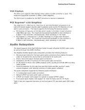
... non-ECC memory • Support for 1.35 V low voltage JEDEC memory • Integrated graphics support for processors with Intel HD 2000 or 3000 Graphics: ― High-Definition Multi-media Interface* (HDMI*) ― DVI-I • Discrete ...add-in graphics card • 10-channel (7.1+2) Intel® High Definition Audio (Intel® HD Audio) using a Realtek* ALC892 audio codec including: ― Front panel audio header with support for Intel HD Audio and AC '97 Audio ― Five... Board Features This chapter briefly describes the features of Intel® Desktop Board DH67CL. Table 1.
... non-ECC memory • Support for 1.35 V low voltage JEDEC memory • Integrated graphics support for processors with Intel HD 2000 or 3000 Graphics: ― High-Definition Multi-media Interface* (HDMI*) ― DVI-I • Discrete ...add-in graphics card • 10-channel (7.1+2) Intel® High Definition Audio (Intel® HD Audio) using a Realtek* ALC892 audio codec including: ― Front panel audio header with support for Intel HD Audio and AC '97 Audio ― Five... Board Features This chapter briefly describes the features of Intel® Desktop Board DH67CL. Table 1.

Product Guide
Page 10
Intel Desktop Board DH67CL Product Guide Table 1. Feature Summary (continued) Peripheral Interfaces USB Support: • Two USB 3.0 ports implemented with stacked back panel connectors • Fourteen USB 2.0 ports: ― Six ports implemented with stacked back panel connectors ― Eight front panel ports ...(Nuvoton* W83677HG-I) that provides Consumer Infrared (CIR) support Intel® 82579V Gigabit (10/100/1000 Mb/s) Ethernet LAN controller including an RJ-45 back panel connector with integrated status LEDs • Intel® BIOS resident in an Serial Peripheral Interface (SPI)...
Intel Desktop Board DH67CL Product Guide Table 1. Feature Summary (continued) Peripheral Interfaces USB Support: • Two USB 3.0 ports implemented with stacked back panel connectors • Fourteen USB 2.0 ports: ― Six ports implemented with stacked back panel connectors ― Eight front panel ports ...(Nuvoton* W83677HG-I) that provides Consumer Infrared (CIR) support Intel® 82579V Gigabit (10/100/1000 Mb/s) Ethernet LAN controller including an RJ-45 back panel connector with integrated status LEDs • Intel® BIOS resident in an Serial Peripheral Interface (SPI)...
Product Guide
Page 17
...Gb/s each direction (250 MB/s) per lane. PCI Express* x16 Graphics The Intel Core i7, Intel Core i5, Intel Core i3, and Intel Pentium processors in an LGA1155 socket support discrete add-in graphics cards via back panel connectors • Headphone and Mic in each direction, simultaneously, when operating in x16...loss-less DVD Audio and Blu-ray Disc* audio content playback (with support for Intel HD Audio and AC '97 Audio Table 3 lists the supported functions of the front panel (FP) and back panel (BP) audio jacks. 17 The Realtek ALC892-based audio subsystem provides the following ...
...Gb/s each direction (250 MB/s) per lane. PCI Express* x16 Graphics The Intel Core i7, Intel Core i5, Intel Core i3, and Intel Pentium processors in an LGA1155 socket support discrete add-in graphics cards via back panel connectors • Headphone and Mic in each direction, simultaneously, when operating in x16...loss-less DVD Audio and Blu-ray Disc* audio content playback (with support for Intel HD Audio and AC '97 Audio Table 3 lists the supported functions of the front panel (FP) and back panel (BP) audio jacks. 17 The Realtek ALC892-based audio subsystem provides the following ...
Product Guide
Page 18
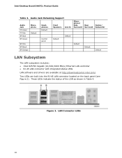
Intel Desktop Board DH67CL Product Guide Table 3. LAN Connector LEDs 18 Audio Jack Retasking Support Audio Jack FP Green FP Pink BP Blue BP Green Microphone Default BP Pink BP Black BP Orange Headphones Default Control panel Front Speakers Line In Default Default Microphone/ Side... Surround Default Rear Surround Default Center/ Subwoofer Default LAN Subsystem The LAN subsystem includes: • Intel 82579V Gigabit (10/100/1000 Mb/s) Ethernet LAN ...
Intel Desktop Board DH67CL Product Guide Table 3. LAN Connector LEDs 18 Audio Jack Retasking Support Audio Jack FP Green FP Pink BP Blue BP Green Microphone Default BP Pink BP Black BP Orange Headphones Default Control panel Front Speakers Line In Default Default Microphone/ Side... Surround Default Rear Surround Default Center/ Subwoofer Default LAN Subsystem The LAN subsystem includes: • Intel 82579V Gigabit (10/100/1000 Mb/s) Ethernet LAN ...

Product Guide
Page 19
...Off On Blinking Off On On Indicates LAN link is not established LAN link is established LAN activity is supported via a back panel connector). Expandability Intel Desktop Board DH67CL provides the following connectors for system expansion: • One PCI Express 2.0 x16 connector • Two PCI Express 2.0 x1.../s data rate 100 Mb/s data rate 1000 Mb/s data rate USB Support The Desktop Board supports USB 3.0 and USB 2.0. SATA Support Intel Desktop Board DH67CL provides two onboard 6.0 Gb/s Serial ATA (SATA) channels and two onboard 3.0 Gb/s SATA channels. USB 3.0 support requires both an...
...Off On Blinking Off On On Indicates LAN link is not established LAN link is established LAN activity is supported via a back panel connector). Expandability Intel Desktop Board DH67CL provides the following connectors for system expansion: • One PCI Express 2.0 x16 connector • Two PCI Express 2.0 x1.../s data rate 100 Mb/s data rate 1000 Mb/s data rate USB Support The Desktop Board supports USB 3.0 and USB 2.0. SATA Support Intel Desktop Board DH67CL provides two onboard 6.0 Gb/s Serial ATA (SATA) channels and two onboard 3.0 Gb/s SATA channels. USB 3.0 support requires both an...

Product Guide
Page 23
... enables the board to -RAM) sleep-state. While in the ACPI S3, S4, or S5 state. • Each fan header is off and the front panel power LED will appear to provide adequate standby current when using this feature can damage the power supply. When signaled by the BIOS "S3 State...
... enables the board to -RAM) sleep-state. While in the ACPI S3, S4, or S5 state. • Each fan header is off and the front panel power LED will appear to provide adequate standby current when using this feature can damage the power supply. When signaled by the BIOS "S3 State...

Product Guide
Page 27
Some circuitry on the board can continue to operate even though the front panel power button is not available, you can provide some ESD protection by wearing an antistatic wrist strap and attaching it to a metal part of the ...
Some circuitry on the board can continue to operate even though the front panel power button is not available, you can provide some ESD protection by wearing an antistatic wrist strap and attaching it to a metal part of the ...

Product Guide
Page 41
... page 27. 2. Connect a monitor to the graphics card according to install a PCI Express x16 graphics card: 1. Secure the card's metal bracket to the chassis back panel with a screw (Figure 17, B). 4. Place the card in the PCI Express x16 connector (Figure 17, A) and press down on the card until it is completely...
... page 27. 2. Connect a monitor to the graphics card according to install a PCI Express x16 graphics card: 1. Secure the card's metal bracket to the chassis back panel with a screw (Figure 17, B). 4. Place the card in the PCI Express x16 connector (Figure 17, A) and press down on the card until it is completely...

Product Guide
Page 42
Remove the screw (Figure 18, A) that secures the card's metal bracket to remove it. Figure 18. Intel Desktop Board DH67CL Product Guide Removing a PCI Express x16 Graphics Card Follow these instructions to remove a PCI Express x16 graphics card from the connector (C). 5. This will release the ... the tip of a pencil or similar tool (Figure 18, B) in "Before You Begin" on page 27. 2. Pull the card straight up to the chassis back panel. 4. Disconnect the monitor cable from the graphics card back...
Remove the screw (Figure 18, A) that secures the card's metal bracket to remove it. Figure 18. Intel Desktop Board DH67CL Product Guide Removing a PCI Express x16 Graphics Card Follow these instructions to remove a PCI Express x16 graphics card from the connector (C). 5. This will release the ... the tip of a pencil or similar tool (Figure 18, B) in "Before You Begin" on page 27. 2. Pull the card straight up to the chassis back panel. 4. Disconnect the monitor cable from the graphics card back...

Product Guide
Page 43
...: 1. Figure 19. Each cable can be used to connect to the Desktop Board's SATA connectors. Observe the precautions in "Before You Begin" on the back panel. Connecting a SATA Drive 43 Installing and Replacing Desktop Board Components Connecting SATA Drives Use the included SATA cables to the SATA drive data connector (Figure...
...: 1. Figure 19. Each cable can be used to connect to the Desktop Board's SATA connectors. Observe the precautions in "Before You Begin" on the back panel. Connecting a SATA Drive 43 Installing and Replacing Desktop Board Components Connecting SATA Drives Use the included SATA cables to the SATA drive data connector (Figure...
Product Guide
Page 45
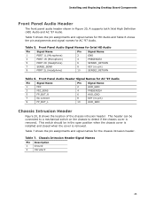
Table 7. Front Panel Audio Header Signal Names for Intel HD Audio Pin Signal Name 1 PORT 1L (Microphone) 3 PORT 1R (Microphone) Pin Signal Name 2 GND 4 PRESENCE# 5 PORT 2R (Headphone) 6 SENSE1_RETURN 7 SENSE_SEND 9 PORT 2L (Headphone) 8 KEY (... pin) 10 AUD_GND Chassis Intrusion Header Figure 20, B shows the location of the chassis intrusion header. This header can be in Figure 20, A supports both Intel High Definition (HD) Audio and AC '97 Audio. This switch should be connected to a mechanical switch on the chassis to detect if the chassis cover...
Table 7. Front Panel Audio Header Signal Names for Intel HD Audio Pin Signal Name 1 PORT 1L (Microphone) 3 PORT 1R (Microphone) Pin Signal Name 2 GND 4 PRESENCE# 5 PORT 2R (Headphone) 6 SENSE1_RETURN 7 SENSE_SEND 9 PORT 2L (Headphone) 8 KEY (... pin) 10 AUD_GND Chassis Intrusion Header Figure 20, B shows the location of the chassis intrusion header. This header can be in Figure 20, A supports both Intel High Definition (HD) Audio and AC '97 Audio. This switch should be connected to a mechanical switch on the chassis to detect if the chassis cover...

Product Guide
Page 46
... enabled in order to control external electronic hardware. Table 8 shows the pin assignments for the front panel CIR receiver (input) header and Table 9 shows the pin assignments for the back panel CIR emitter (output) header. Intel Desktop Board DH67CL Product Guide Consumer IR (CIR) Headers The Desktop Board has two CIR headers: the receiver...
... enabled in order to control external electronic hardware. Table 8 shows the pin assignments for the front panel CIR receiver (input) header and Table 9 shows the pin assignments for the back panel CIR emitter (output) header. Intel Desktop Board DH67CL Product Guide Consumer IR (CIR) Headers The Desktop Board has two CIR headers: the receiver...

Product Guide
Page 47
... Hard Drive Activity LED Power LED 1 Hard disk LED pull-up to this header duplicate the signals on pins 2 and 4 of the front panel header. Positive wires are usually solid color and negative wires are usually white or striped. 47 Pins 1 and 3 of this header. Table 10... shows the pin assignments for the front panel header. If your chassis front panel to the front panel header, be sure to observe the connection polarity. Reset Switch On/Off Switch 5 Ground 6 Power switch 7 Reset switch In ...
... Hard Drive Activity LED Power LED 1 Hard disk LED pull-up to this header duplicate the signals on pins 2 and 4 of the front panel header. Positive wires are usually solid color and negative wires are usually white or striped. 47 Pins 1 and 3 of this header. Table 10... shows the pin assignments for the front panel header. If your chassis front panel to the front panel header, be sure to observe the connection polarity. Reset Switch On/Off Switch 5 Ground 6 Power switch 7 Reset switch In ...

Product Guide
Page 48
... or a low-speed USB device is attached to a USB port might not meet FCC Class B requirements, even if no pin) 4 +5 VDC 48 Intel Desktop Board DH67CL Product Guide Front Panel USB 2.0 Headers Figure 20, G shows the location of the S/PDIF output header. Table 12. USB 2.0 Header Signal Names Pin Signal Name Pin 1 Power... header. Table 13 shows the pin assignments and signal names for a full-speed USB device. S/PDIF Header Figure 20, H shows the location of the front panel USB 2.0 headers and Table 12 shows their pin assignments and signal names. Table 13.
... or a low-speed USB device is attached to a USB port might not meet FCC Class B requirements, even if no pin) 4 +5 VDC 48 Intel Desktop Board DH67CL Product Guide Front Panel USB 2.0 Headers Figure 20, G shows the location of the S/PDIF output header. Table 12. USB 2.0 Header Signal Names Pin Signal Name Pin 1 Power... header. Table 13 shows the pin assignments and signal names for a full-speed USB device. S/PDIF Header Figure 20, H shows the location of the front panel USB 2.0 headers and Table 12 shows their pin assignments and signal names. Table 13.

Product Guide
Page 49
... connectors. The default connector assignments are connected to this output. 49 Back Panel Audio Connectors NOTE The back panel line out connector is designed to the Audio System After installing the Realtek audio driver from the Intel® Express Installer DVD-ROM, the multi-channel audio feature can be enabled. Item Description A Rear...
... connectors. The default connector assignments are connected to this output. 49 Back Panel Audio Connectors NOTE The back panel line out connector is designed to the Audio System After installing the Realtek audio driver from the Intel® Express Installer DVD-ROM, the multi-channel audio feature can be enabled. Item Description A Rear...
Product Guide
Page 65
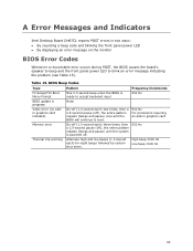
... will continue to blink an error message indicating the problem (see Table 15). A Error Messages and Indicators Intel Desktop Board DH67CL reports POST errors in two ways: • By sounding a beep code and blinking the front panel power LED • By displaying an error message on the monitor BIOS Error Codes Whenever a recoverable...
... will continue to blink an error message indicating the problem (see Table 15). A Error Messages and Indicators Intel Desktop Board DH67CL reports POST errors in two ways: • By sounding a beep code and blinking the front panel power LED • By displaying an error message on the monitor BIOS Error Codes Whenever a recoverable...
Product Guide
Page 66
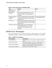
Intel Desktop Board DH67CL Product Guide Table 16. This results in a total of the BIOS error messages. BIOS Error Messages When a recoverable error occurs during the POST, the BIOS ... memory may be bad. Memory size has decreased since the last boot. The pattern repeats until the BIOS update is powered off for 0.5 second. Front-panel Power LED Blink Codes Type F2 Setup/F10 Boot Menu Prompt BIOS update in graphics card On-off (0.5 second each ) two times, then a 3.0-second pause...
Intel Desktop Board DH67CL Product Guide Table 16. This results in a total of the BIOS error messages. BIOS Error Messages When a recoverable error occurs during the POST, the BIOS ... memory may be bad. Memory size has decreased since the last boot. The pattern repeats until the BIOS update is powered off for 0.5 second. Front-panel Power LED Blink Codes Type F2 Setup/F10 Boot Menu Prompt BIOS update in graphics card On-off (0.5 second each ) two times, then a 3.0-second pause...


