

Product Guide
Page 5
... Operating Systems 11 Desktop Board Components 12 Processor ...14 Intel® H67 Express Chipset 15 Main Memory...15 Graphics Subsystem 16 Integrated Graphics 16 Intel® HD Graphics 16 High-Definition Multimedia Interface* (HDMI 16 Digital Visual Interface (DVI-I 16 VGA Displays 17 PCI Express* x16 Graphics 17 Audio Subsystem 17 LAN Subsystem 18 USB Support...
... Operating Systems 11 Desktop Board Components 12 Processor ...14 Intel® H67 Express Chipset 15 Main Memory...15 Graphics Subsystem 16 Integrated Graphics 16 Intel® HD Graphics 16 High-Definition Multimedia Interface* (HDMI 16 Digital Visual Interface (DVI-I 16 VGA Displays 17 PCI Express* x16 Graphics 17 Audio Subsystem 17 LAN Subsystem 18 USB Support...
Product Guide
Page 6
Intel Desktop Board DH67CL Product Guide Installing the I/O Shield 29 Installing and Removing the Desktop Board 30 Installing and ... Installing DIMMs 38 Removing DIMMs 40 Installing and Removing PCI Express x16 Graphics Cards 40 Installing a PCI Express x16 Graphics Card 40 Removing a PCI Express x16 Graphics Card 42 Connecting SATA Drives 43 Connecting to the Internal Headers 44 ... the ISO Image BIOS Update File 62 Obtaining the BIOS Update File 62 Updating the BIOS with the Intel Flash Memory Update Utility 63 Updating the BIOS with the ISO Image BIOS Update File 63 Recovering the ...
Intel Desktop Board DH67CL Product Guide Installing the I/O Shield 29 Installing and Removing the Desktop Board 30 Installing and ... Installing DIMMs 38 Removing DIMMs 40 Installing and Removing PCI Express x16 Graphics Cards 40 Installing a PCI Express x16 Graphics Card 40 Removing a PCI Express x16 Graphics Card 42 Connecting SATA Drives 43 Connecting to the Internal Headers 44 ... the ISO Image BIOS Update File 62 Obtaining the BIOS Update File 62 Updating the BIOS with the Intel Flash Memory Update Utility 63 Updating the BIOS with the ISO Image BIOS Update File 63 Recovering the ...
Product Guide
Page 7
... Channel Memory Configuration with Two DIMMs 36 13. Use DDR3 DIMMs 38 16. Installing a PCI Express x16 Graphics Card 41 18. Back Panel Audio Connectors 49 22. Connecting Power Supply Cables 51 24. Intel Desktop Board DH67CL Components 12 2. Installing the I/O Shield 29 5. Remove the Processor from the Protective Cover 33 9. Installing a DIMM...
... Channel Memory Configuration with Two DIMMs 36 13. Use DDR3 DIMMs 38 16. Installing a PCI Express x16 Graphics Card 41 18. Back Panel Audio Connectors 49 22. Connecting Power Supply Cables 51 24. Intel Desktop Board DH67CL Components 12 2. Installing the I/O Shield 29 5. Remove the Processor from the Protective Cover 33 9. Installing a DIMM...

Product Guide
Page 9
... the Desktop Board. Table 1 summarizes the major features of Intel® Desktop Board DH67CL. Table 1. Feature Summary Form Factor Processor Chipset Memory Graphics Audio ATX (243.84 millimeters [9.6 inches] x 294.64 millimeters [11.6 inches]) • Intel® Core™ i7, Intel® Core™ i5, and Intel® Core™ i3 processors in an LGA1155 socket...
... the Desktop Board. Table 1 summarizes the major features of Intel® Desktop Board DH67CL. Table 1. Feature Summary Form Factor Processor Chipset Memory Graphics Audio ATX (243.84 millimeters [9.6 inches] x 294.64 millimeters [11.6 inches]) • Intel® Core™ i7, Intel® Core™ i5, and Intel® Core™ i3 processors in an LGA1155 socket...
Product Guide
Page 15
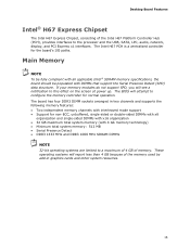
The board has four DDR3 DIMM sockets arranged in graphics cards and other system resources. 15 The BIOS will attempt to configure the memory controller for the board's I/O paths. Desktop Board Features Intel® H67 Express Chipset The Intel H67 Express Chipset, consisting of memory. Main Memory NOTE To be fully ... • DDR3 1333 MHz and DDR3 1066 MHz SDRAM DIMMs NOTE 32-bit operating systems are limited to a maximum of 4 GB of the Intel H67 Platform Controller Hub (PCH), provides interfaces to this effect on the screen at power up. If your memory modules do not support SPD, ...
The board has four DDR3 DIMM sockets arranged in graphics cards and other system resources. 15 The BIOS will attempt to configure the memory controller for the board's I/O paths. Desktop Board Features Intel® H67 Express Chipset The Intel H67 Express Chipset, consisting of memory. Main Memory NOTE To be fully ... • DDR3 1333 MHz and DDR3 1066 MHz SDRAM DIMMs NOTE 32-bit operating systems are limited to a maximum of 4 GB of the Intel H67 Platform Controller Hub (PCH), provides interfaces to this effect on the screen at power up. If your memory modules do not support SPD, ...
Product Guide
Page 16
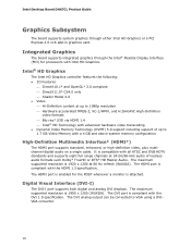
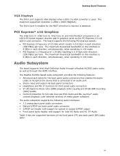
... multichannel digital audio on a single cable. The DVI analog output can be converted to 1.7 GB Video Memory with the DVI 1.0 specification. Intel Desktop Board DH67CL Product Guide Graphics Subsystem The board supports system graphics through the Intel® Flexible Display Interface (FDI) for the POST whenever a monitor is attached. The HDMI port is compliant with...
... multichannel digital audio on a single cable. The DVI analog output can be converted to 1.7 GB Video Memory with the DVI 1.0 specification. Intel Desktop Board DH67CL Product Guide Graphics Subsystem The board supports system graphics through the Intel® Flexible Display Interface (FDI) for the POST whenever a monitor is attached. The HDMI port is compliant with...
Product Guide
Page 17
... the PCI Express 2.0 x16 add-in x16 mode. The Realtek ALC892-based audio subsystem provides the following features: • Advanced jack sense for Intel HD Audio and AC '97 Audio Table 3 lists the supported functions of 2.5 GHz which results in 5.0 Gb/s in 2.5 Gb/s each direction...1.25 GHz resulting in each direction (500 MB/s) per lane. PCI Express* x16 Graphics The Intel Core i7, Intel Core i5, Intel Core i3, and Intel Pentium processors in an LGA1155 socket support discrete add-in graphics cards via back panel connectors • Headphone and Mic in functions for the POST ...
... the PCI Express 2.0 x16 add-in x16 mode. The Realtek ALC892-based audio subsystem provides the following features: • Advanced jack sense for Intel HD Audio and AC '97 Audio Table 3 lists the supported functions of 2.5 GHz which results in 5.0 Gb/s in 2.5 Gb/s each direction...1.25 GHz resulting in each direction (500 MB/s) per lane. PCI Express* x16 Graphics The Intel Core i7, Intel Core i5, Intel Core i3, and Intel Pentium processors in an LGA1155 socket support discrete add-in graphics cards via back panel connectors • Headphone and Mic in functions for the POST ...

Product Guide
Page 39
...install a DIMM, follow these steps: 1. Figure 16. Align the small notch at either end of the DIMM into place. Reinstall the PCI Express graphics card if one was removed in place. 10. Turn off the computer and disconnect the AC power cord. 3. Make sure the clips are pushed ...outward to the open position. 6. If a full length PCI Express graphics card is inserted, push down on page 27. 2. Turn off all peripheral devices connected to the DIMM sockets. Insert the bottom edge of the DIMM...
...install a DIMM, follow these steps: 1. Figure 16. Align the small notch at either end of the DIMM into place. Reinstall the PCI Express graphics card if one was removed in place. 10. Turn off the computer and disconnect the AC power cord. 3. Make sure the clips are pushed ...outward to the open position. 6. If a full length PCI Express graphics card is inserted, push down on page 27. 2. Turn off all peripheral devices connected to the DIMM sockets. Insert the bottom edge of the DIMM...

Product Guide
Page 40
... Desktop Board components and/or traces may be damaged by the edges, lift it in the connector, an electrical short may be damaged. 40 Intel Desktop Board DH67CL Product Guide Removing DIMMs To remove a DIMM, follow these steps: 1. Remove the computer's cover. 5. Turn off all peripheral devices connected to the DIMMs. 6. ..., make sure that the card is fully seated in the upright position (closed); Reinstall the PCI Express graphics card if one was removed in "Before You Begin" on the system. Observe the precautions in Step 5 and reconnect any other parts you power on...
... Desktop Board components and/or traces may be damaged by the edges, lift it in the connector, an electrical short may be damaged. 40 Intel Desktop Board DH67CL Product Guide Removing DIMMs To remove a DIMM, follow these steps: 1. Remove the computer's cover. 5. Turn off all peripheral devices connected to the DIMMs. 6. ..., make sure that the card is fully seated in the upright position (closed); Reinstall the PCI Express graphics card if one was removed in "Before You Begin" on the system. Observe the precautions in Step 5 and reconnect any other parts you power on...

Product Guide
Page 41
... the chassis back panel with a screw (Figure 17, B). 4. Secure the card's metal bracket to install a PCI Express x16 graphics card: 1. Installing a PCI Express x16 Graphics Card 41 Figure 17. Connect a monitor to the graphics card according to the manufacturer's instructions. Observe the precautions in the connector and the card retention notch on the...
... the chassis back panel with a screw (Figure 17, B). 4. Secure the card's metal bracket to install a PCI Express x16 graphics card: 1. Installing a PCI Express x16 Graphics Card 41 Figure 17. Connect a monitor to the graphics card according to the manufacturer's instructions. Observe the precautions in the connector and the card retention notch on the...

Product Guide
Page 42
Disconnect the monitor cable from the connector (C). 5. This will release the card from the graphics card back panel connector. 3. Removing a PCI Express x16 Graphics Card 42 Observe the precautions in the notch. Push the card ejector lever down using the tip of a pencil or similar tool (Figure 18, B) in "... the screw (Figure 18, A) that secures the card's metal bracket to remove it. Figure 18. Pull the card straight up to the chassis back panel. 4. Intel Desktop Board DH67CL Product Guide Removing a PCI Express x16 Graphics Card Follow these instructions to remove a PCI Express x16...
Disconnect the monitor cable from the connector (C). 5. This will release the card from the graphics card back panel connector. 3. Removing a PCI Express x16 Graphics Card 42 Observe the precautions in the notch. Push the card ejector lever down using the tip of a pencil or similar tool (Figure 18, B) in "... the screw (Figure 18, A) that secures the card's metal bracket to remove it. Figure 18. Pull the card straight up to the chassis back panel. 4. Intel Desktop Board DH67CL Product Guide Removing a PCI Express x16 Graphics Card Follow these instructions to remove a PCI Express x16...

Product Guide
Page 51
... 23, A). 3. Connecting Power Supply Cables 1. Figure 23. The 2 x 12 pin main power connector (Figure 23, B) is recommended that you do not install a PCI Express x16 graphics card unless it is backwards compatible with ATX12V power supplies with 2 x 10 connectors. Installing and Replacing Desktop Board Components Connecting Power Supply Cables CAUTION Failure...
... 23, A). 3. Connecting Power Supply Cables 1. Figure 23. The 2 x 12 pin main power connector (Figure 23, B) is recommended that you do not install a PCI Express x16 graphics card unless it is backwards compatible with ATX12V power supplies with 2 x 10 connectors. Installing and Replacing Desktop Board Components Connecting Power Supply Cables CAUTION Failure...
Product Guide
Page 65
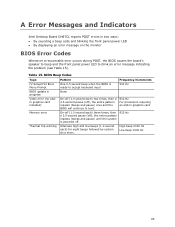
...932 Hz Alternate high and low beeps (1.0 second each) for eight beeps followed by system shut down. Table 15. A Error Messages and Indicators Intel Desktop Board DH67CL reports POST errors in two ways: • By sounding a beep code and blinking the front panel power LED • By displaying an error ... speaker to beep and the front panel power LED to boot. 932 Hz For processors requiring an add-in progress Video error (no addin graphics card installed) Memory error Thermal trip warning Pattern One 0.5 second beep when the BIOS is powered off ), the entire pattern repeats (beeps and...
...932 Hz Alternate high and low beeps (1.0 second each) for eight beeps followed by system shut down. Table 15. A Error Messages and Indicators Intel Desktop Board DH67CL reports POST errors in two ways: • By sounding a beep code and blinking the front panel power LED • By displaying an error ... speaker to beep and the front panel power LED to boot. 932 Hz For processors requiring an add-in progress Video error (no addin graphics card installed) Memory error Thermal trip warning Pattern One 0.5 second beep when the BIOS is powered off ), the entire pattern repeats (beeps and...
Product Guide
Page 66
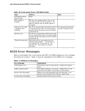
...the BIOS error messages. CMOS memory may be bad. System did not find a device to reset values. For processors requiring an add-in graphics card On-off (0.5 second each ) two times, then a 3.0-second pause (off . BIOS Error Messages Error Message CMOS Battery Low CMOS... Checksum Bad Memory Size Decreased No Boot Device Available Explanation The battery may have been corrupted. Intel Desktop Board DH67CL Product Guide Table 16. If no addin graphics card installed) Memory error Thermal trip warning Pattern None Note Off when the update begins, then on...
...the BIOS error messages. CMOS memory may be bad. System did not find a device to reset values. For processors requiring an add-in graphics card On-off (0.5 second each ) two times, then a 3.0-second pause (off . BIOS Error Messages Error Message CMOS Battery Low CMOS... Checksum Bad Memory Size Decreased No Boot Device Available Explanation The battery may have been corrupted. Intel Desktop Board DH67CL Product Guide Table 16. If no addin graphics card installed) Memory error Thermal trip warning Pattern None Note Off when the update begins, then on...
Product Specification
Page 7
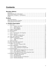
... 1.1.2 Board Layout 13 1.1.3 Block Diagram 15 1.2 Legacy Considerations 16 1.3 Online Support 16 1.4 Processor 17 1.4.1 PCI Express x16 Graphics 17 1.5 System Memory 18 1.5.1 Memory Configurations 19 1.6 Intel® H67 Express Chipset 21 1.7 Graphics Subsystem 21 1.7.1 Integrated Graphics 21 1.7.2 USB 23 1.8 SATA Interfaces 24 1.9 Real-Time Clock Subsystem 25 1.10 Legacy I/O Controller 25 1.10.1 Consumer Infrared...
... 1.1.2 Board Layout 13 1.1.3 Block Diagram 15 1.2 Legacy Considerations 16 1.3 Online Support 16 1.4 Processor 17 1.4.1 PCI Express x16 Graphics 17 1.5 System Memory 18 1.5.1 Memory Configurations 19 1.6 Intel® H67 Express Chipset 21 1.7 Graphics Subsystem 21 1.7.1 Integrated Graphics 21 1.7.2 USB 23 1.8 SATA Interfaces 24 1.9 Real-Time Clock Subsystem 25 1.10 Legacy I/O Controller 25 1.10.1 Consumer Infrared...

Product Specification
Page 11
... processors with up to 95W TDP in an LGA1155 socket ― One PCI Express* 2.0 x16 graphics interface ― Integrated memory controller with dual channel DDR3 memory support ― Integrated graphics processing (processors with Intel® Graphics Technology) ― External graphics interface controller • Four 240-pin DDR3 SDRAM Dual Inline Memory Module (DIMM) sockets •...
... processors with up to 95W TDP in an LGA1155 socket ― One PCI Express* 2.0 x16 graphics interface ― Integrated memory controller with dual channel DDR3 memory support ― Integrated graphics processing (processors with Intel® Graphics Technology) ― External graphics interface controller • Four 240-pin DDR3 SDRAM Dual Inline Memory Module (DIMM) sockets •...

Product Specification
Page 17
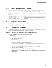
... direction, simultaneously, for this board. 1.4.1 PCI Express x16 Graphics The Intel Core i7, Intel Core i5, and Intel Core i3 processors in an LGA1155 socket support discrete add in graphics cards via the PCI Express 2.0 x16 graphics connector: • Supports PCI Express GEN2 frequency of 2.5 ...GHz resulting in the future. The maximum theoretical bandwidth on the web site above are only supported when falling within the wattage requirements of Intel Desktop Board DH67CL...
... direction, simultaneously, for this board. 1.4.1 PCI Express x16 Graphics The Intel Core i7, Intel Core i5, and Intel Core i3 processors in an LGA1155 socket support discrete add in graphics cards via the PCI Express 2.0 x16 graphics connector: • Supports PCI Express GEN2 frequency of 2.5 ...GHz resulting in the future. The maximum theoretical bandwidth on the web site above are only supported when falling within the wattage requirements of Intel Desktop Board DH67CL...
Product Specification
Page 21
... MPEG-2, VC-1/WMV and H.264/AVC Hi-Definition video formats ⎯ Intel® HD Technology with 4 GB and above system memory configuration 21 The Intel H67 Express Chipset is a centralized controller for processors with Intel Graphics Technology. 1.7.1.1 Intel® High Definition (Intel® HD) Graphics The Intel HD graphics controller features the following: • 3D Features ⎯ DirectX10.1 and...
... MPEG-2, VC-1/WMV and H.264/AVC Hi-Definition video formats ⎯ Intel® HD Technology with 4 GB and above system memory configuration 21 The Intel H67 Express Chipset is a centralized controller for processors with Intel Graphics Technology. 1.7.1.1 Intel® High Definition (Intel® HD) Graphics The Intel HD graphics controller features the following: • 3D Features ⎯ DirectX10.1 and...

Product Specification
Page 69
Overview of BIOS Features 3.11 BIOS Performance Features The BIOS includes the following options to provide custom performance enhancements when using Intel Core i7, Intel Core i5, and Intel Core i3 processors in an LGA1155 socket. • Processor Maximum Non-Turbo Ratio (processor multiplier can only be adjusted down) • Memory multiplier adjustment • Memory voltage adjustment • Graphics multiplier adjustment 69
Overview of BIOS Features 3.11 BIOS Performance Features The BIOS includes the following options to provide custom performance enhancements when using Intel Core i7, Intel Core i5, and Intel Core i3 processors in an LGA1155 socket. • Processor Maximum Non-Turbo Ratio (processor multiplier can only be adjusted down) • Memory multiplier adjustment • Memory voltage adjustment • Graphics multiplier adjustment 69

Product Specification
Page 74
... 0x0F Pass entry point of the PEI core PEI before MRC PEI Platform driver 0x11 Set bootmode, GPIO init 0x12 Early chipset register programming including graphics init 0x13 Basic PCH init, discrete device init (1394, SATA) 0x14 LAN init 0x15 Exit early platform init driver PEI SMBUS 0x16 SMBUSriver init 0x17... Configuring memory 0x28 Testing memory 0x29 Exit MRC driver PEI after MRC 0x2A Start to Program MTRR Settings 0x2B Done Programming MTRR Settings continued 74 Intel Desktop Board DH67CL Technical Product Specification Table 44.
... 0x0F Pass entry point of the PEI core PEI before MRC PEI Platform driver 0x11 Set bootmode, GPIO init 0x12 Early chipset register programming including graphics init 0x13 Basic PCH init, discrete device init (1394, SATA) 0x14 LAN init 0x15 Exit early platform init driver PEI SMBUS 0x16 SMBUSriver init 0x17... Configuring memory 0x28 Testing memory 0x29 Exit MRC driver PEI after MRC 0x2A Start to Program MTRR Settings 0x2B Done Programming MTRR Settings continued 74 Intel Desktop Board DH67CL Technical Product Specification Table 44.


