
Technical Product Specification
Page 7
... Processor 18 1.4 System Memory 19 1.4.1 Memory Configurations 20 1.5 Intel® QS77 Express Chipset 22 1.5.1 Direct Media Interface (DMI 22 1.5.2 Display Interfaces 22 1.6 Graphics Subsystem 22 1.6.1 Integrated Graphics 22 1.6.2 USB 24 1.7 SATA Interface 24 1.7.1 AHCI Mode 24 1.8 Real-Time... Clock Subsystem 25 1.9 LAN Subsystem 25 1.9.1 Intel® 82579V Gigabit Ethernet Controller 26 1.9.2 LAN Subsystem Software 26 1.9.3...
... Processor 18 1.4 System Memory 19 1.4.1 Memory Configurations 20 1.5 Intel® QS77 Express Chipset 22 1.5.1 Direct Media Interface (DMI 22 1.5.2 Display Interfaces 22 1.6 Graphics Subsystem 22 1.6.1 Integrated Graphics 22 1.6.2 USB 24 1.7 SATA Interface 24 1.7.1 AHCI Mode 24 1.8 Real-Time... Clock Subsystem 25 1.9 LAN Subsystem 25 1.9.1 Intel® 82579V Gigabit Ethernet Controller 26 1.9.2 LAN Subsystem Software 26 1.9.3...

Technical Product Specification
Page 8
Intel Desktop Board D33217GKE Technical Product Specification 2 Technical Reference 2.1 Memory Resources 35 2.1.1 Addressable Memory 35 2.1.2 Memory Map 37 2.2 Connectors and Headers 37 2.2.1 Back ...Thermal Considerations 50 2.7 Reliability 53 2.8 Environmental 53 3 Overview of BIOS Features 3.1 Introduction 55 3.2 BIOS Flash Memory Organization 56 3.3 System Management BIOS (SMBIOS 56 3.4 Legacy USB Support 56 3.5 BIOS Updates 57 3.5.1 Language Support 57 3.5.2 Custom Splash Screen 58 3.6 BIOS Recovery 58 3.7 Boot Options 59 3.7.1 Network Boot 59 3.7.2 Booting Without Attached...
Intel Desktop Board D33217GKE Technical Product Specification 2 Technical Reference 2.1 Memory Resources 35 2.1.1 Addressable Memory 35 2.1.2 Memory Map 37 2.2 Connectors and Headers 37 2.2.1 Back ...Thermal Considerations 50 2.7 Reliability 53 2.8 Environmental 53 3 Overview of BIOS Features 3.1 Introduction 55 3.2 BIOS Flash Memory Organization 56 3.3 System Management BIOS (SMBIOS 56 3.4 Legacy USB Support 56 3.5 BIOS Updates 57 3.5.1 Language Support 57 3.5.2 Custom Splash Screen 58 3.6 BIOS Recovery 58 3.7 Boot Options 59 3.7.1 Network Boot 59 3.7.2 Booting Without Attached...
Technical Product Specification
Page 9
Contents 5.1.5 ENERGY STAR* 5.2, e-Standby, and ErP Compliance 78 5.1.6 Regulatory Compliance Marks (Board Level 79 5.2 Battery Disposal Information 80 Figures 1. Connection Diagram for Front Panel USB 2.0 Dual-Port Header 45 13. Board Dimensions 48 15. Location of the BIOS Configuration Setup Jumper 46 14. Connection Diagram for Front Panel Header 44 ...
Contents 5.1.5 ENERGY STAR* 5.2, e-Standby, and ErP Compliance 78 5.1.6 Regulatory Compliance Marks (Board Level 79 5.2 Battery Disposal Information 80 Figures 1. Connection Diagram for Front Panel USB 2.0 Dual-Port Header 45 13. Board Dimensions 48 15. Location of the BIOS Configuration Setup Jumper 46 14. Connection Diagram for Front Panel Header 44 ...

Technical Product Specification
Page 10
Components Shown in Figure 1 14 3. LAN Connector LED States 27 6. System Memory Map 37 10. Dual-Port Front Panel USB 2.0 Header 42 13. 19 V Internal Power Supply Connector 43 14. Fan Header Current Capability 50 18. Master Key and User Hard ...Card Connector 41 12. BIOS Setup Configuration Jumper Settings 47 17. Supervisor and User Password Functions 61 25. Port 80h POST Codes 65 29. Intel Desktop Board D33217GKE Technical Product Specification Tables 1. Effects of Pressing the Power Switch 30 7. Safety Standards 71 31. Regulatory Compliance Marks 79 x ...
Components Shown in Figure 1 14 3. LAN Connector LED States 27 6. System Memory Map 37 10. Dual-Port Front Panel USB 2.0 Header 42 13. 19 V Internal Power Supply Connector 43 14. Fan Header Current Capability 50 18. Master Key and User Hard ...Card Connector 41 12. BIOS Setup Configuration Jumper Settings 47 17. Supervisor and User Password Functions 61 25. Port 80h POST Codes 65 29. Intel Desktop Board D33217GKE Technical Product Specification Tables 1. Effects of Pressing the Power Switch 30 7. Safety Standards 71 31. Regulatory Compliance Marks 79 x ...
Technical Product Specification
Page 11
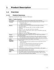
...Hub (PCH) • Integrated graphics support for processors with Intel® Graphics Technology: ― Two High Definition Multimedia Interface* (HDMI*) back panel connectors Intel® High Definition Audio via the HDMI v1.4a interfaces • USB 2.0 ports: ― Three front panel ports (via one... Graphics Audio Peripheral Interfaces Expansion Capabilities BIOS 4.0 inches by 4.0 inches (101.60 millimeters by 101.60 millimeters) • Soldered-down Intel® Core™ i3-3217U processor with up to 17 W TDP ― Integrated graphics ― Integrated memory controller • ...
...Hub (PCH) • Integrated graphics support for processors with Intel® Graphics Technology: ― Two High Definition Multimedia Interface* (HDMI*) back panel connectors Intel® High Definition Audio via the HDMI v1.4a interfaces • USB 2.0 ports: ― Three front panel ports (via one... Graphics Audio Peripheral Interfaces Expansion Capabilities BIOS 4.0 inches by 4.0 inches (101.60 millimeters by 101.60 millimeters) • Soldered-down Intel® Core™ i3-3217U processor with up to 17 W TDP ― Integrated graphics ― Integrated memory controller • ...
Technical Product Specification
Page 22
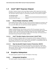
... display data from the frame buffer is processed in the processor with Direct Media Interface (DMI) interconnect provides interfaces to http://www.intel.com/products/desktop/chipsets/index.htm Chapter 2 1.5.1 Direct Media Interface (DMI) Direct Media Interface (DMI) is divided between a ... For information about The Intel QS77 chipset Resources used by the chipset Refer to the processor and the USB, SATA, LPC, LAN, and PCI Express interfaces. Intel Desktop Board D33217GKE Technical Product Specification 1.5 Intel® QS77 Express Chipset Intel QS77 Express Chipset with the...
... display data from the frame buffer is processed in the processor with Direct Media Interface (DMI) interconnect provides interfaces to http://www.intel.com/products/desktop/chipsets/index.htm Chapter 2 1.5.1 Direct Media Interface (DMI) Direct Media Interface (DMI) is divided between a ... For information about The Intel QS77 chipset Resources used by the chipset Refer to the processor and the USB, SATA, LPC, LAN, and PCI Express interfaces. Intel Desktop Board D33217GKE Technical Product Specification 1.5 Intel® QS77 Express Chipset Intel QS77 Express Chipset with the...
Technical Product Specification
Page 24
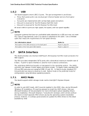
...is reserved for host to the cable. The underlying SATA functionality is as follows: • Three front panel ports (via the Intel QS77 Express Chipset. The SATA controller can operate in the BIOS. In legacy mode, standard IDE I/O and IRQ resources are high... resource steering is attached to device connections. See your Microsoft Windows XP documentation for SSD support. Intel Desktop Board D33217GKE Technical Product Specification 1.6.2 USB The board supports seven USB 2.0 ports. The PCH provides independent SATA ports with a theoretical maximum transfer rate of the front...
...is reserved for host to the cable. The underlying SATA functionality is as follows: • Three front panel ports (via the Intel QS77 Express Chipset. The SATA controller can operate in the BIOS. In legacy mode, standard IDE I/O and IRQ resources are high... resource steering is attached to device connections. See your Microsoft Windows XP documentation for SSD support. Intel Desktop Board D33217GKE Technical Product Specification 1.6.2 USB The board supports seven USB 2.0 ports. The PCH provides independent SATA ports with a theoretical maximum transfer rate of the front...
Technical Product Specification
Page 30
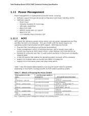
... working state) More than six seconds Fail safe power-off ) Less than six seconds Power-off ) Sleep (ACPI G1 - Intel Desktop Board D33217GKE Technical Product Specification 1.11 Power Management Power management is state... pressed for achieving less than four seconds Soft-off feature...Interface (ACPI) • Hardware support: Power Input Instantly Available PC technology LAN wake capabilities Wake from USB WAKE# signal wake-up (ACPI G0 - ACPI features include: • Plug and Play (including bus and device enumeration) •...
... working state) More than six seconds Fail safe power-off ) Less than six seconds Power-off ) Sleep (ACPI G1 - Intel Desktop Board D33217GKE Technical Product Specification 1.11 Power Management Power management is state... pressed for achieving less than four seconds Soft-off feature...Interface (ACPI) • Hardware support: Power Input Instantly Available PC technology LAN wake capabilities Wake from USB WAKE# signal wake-up (ACPI G0 - ACPI features include: • Plug and Play (including bus and device enumeration) •...
Technical Product Specification
Page 32
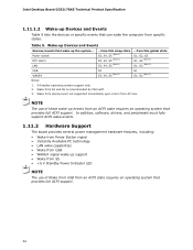
...hardware features, including: • Wake from Power Button signal • Instantly Available PC technology • LAN wake capabilities • Wake from USB • WAKE# signal wake-up support • Wake from S5 • +5 V Standby Power Indicator LED NOTE The use of Wake from...... Wake from device/event not supported immediately upon return from an ACPI state requires an operating system that provides full ACPI support. 32 Intel Desktop Board D33217GKE Technical Product Specification 1.11.1.2 Wake-up Devices and Events Table 9 lists the devices or specific events that can wake ...
...hardware features, including: • Wake from Power Button signal • Instantly Available PC technology • LAN wake capabilities • Wake from USB • WAKE# signal wake-up support • Wake from S5 • +5 V Standby Power Indicator LED NOTE The use of Wake from...... Wake from device/event not supported immediately upon return from an ACPI state requires an operating system that provides full ACPI support. 32 Intel Desktop Board D33217GKE Technical Product Specification 1.11.1.2 Wake-up Devices and Events Table 9 lists the devices or specific events that can wake ...
Technical Product Specification
Page 33
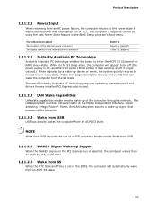
...Last Power State feature in the S3 sleep-state, the computer will automatically wake from an ACPI S5 state. 33 NOTE Wake from USB requires the use of Instantly Available PC technology requires operating system support and drivers for any installed PCI Express add-in the BIOS, the...computer will appear to be set in card. 1.11.2.3 LAN Wake Capabilities LAN wake capabilities enable remote wake-up the computer. 1.11.2.4 Wake from USB USB bus activity wakes the computer from an ACPI S3 state. Upon detecting a Magic Packet* frame, the LAN subsystem asserts a wake-up signal that ...
...Last Power State feature in the S3 sleep-state, the computer will automatically wake from an ACPI S5 state. 33 NOTE Wake from USB requires the use of Instantly Available PC technology requires operating system support and drivers for any installed PCI Express add-in the BIOS, the...computer will appear to be set in card. 1.11.2.3 LAN Wake Capabilities LAN wake capabilities enable remote wake-up the computer. 1.11.2.4 Wake from USB USB bus activity wakes the computer from an ACPI S3 state. Upon detecting a Magic Packet* frame, the LAN subsystem asserts a wake-up signal that ...

Technical Product Specification
Page 37
...Conventional memory 2.2 Connectors and Headers CAUTION Only the following connectors and headers have overcurrent protection: back panel and front panel USB. Dependent on video adapter used. The other internal connectors and headers are not overcurrent protected and should connect only to the... board. Furthermore, improper connection of USB header single wire connectors may eventually overload the overcurrent protection and cause damage to devices inside the computer's chassis, such...
...Conventional memory 2.2 Connectors and Headers CAUTION Only the following connectors and headers have overcurrent protection: back panel and front panel USB. Dependent on video adapter used. The other internal connectors and headers are not overcurrent protected and should connect only to the... board. Furthermore, improper connection of USB header single wire connectors may eventually overload the overcurrent protection and cause damage to devices inside the computer's chassis, such...
Technical Product Specification
Page 38
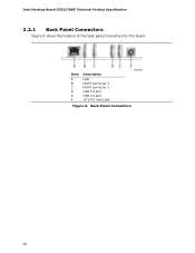
Item A B C D E F Description LAN HDMI connector 2 HDMI connector 1 USB 2.0 port USB 2.0 port 19 V DC input jack Figure 9. Back Panel Connectors 38 Intel Desktop Board D33217GKE Technical Product Specification 2.2.1 Back Panel Connectors Figure 9 shows the location of the back panel connectors for the board.
Item A B C D E F Description LAN HDMI connector 2 HDMI connector 1 USB 2.0 port USB 2.0 port 19 V DC input jack Figure 9. Back Panel Connectors 38 Intel Desktop Board D33217GKE Technical Product Specification 2.2.1 Back Panel Connectors Figure 9 shows the location of the back panel connectors for the board.
Technical Product Specification
Page 40
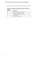
Intel Desktop Board D33217GKE Technical Product Specification Table 11 lists the connectors and headers identified in Figure 10 Item from Figure 10 Description A PCI Express Full-Mini Card connector B PCI Express Half-Mini Card connector C Front panel dual-port USB 2.0 header D Front panel header E Internal DC power connector 40 Table 11. Connectors and Headers Shown in Figure 10.
Intel Desktop Board D33217GKE Technical Product Specification Table 11 lists the connectors and headers identified in Figure 10 Item from Figure 10 Description A PCI Express Full-Mini Card connector B PCI Express Half-Mini Card connector C Front panel dual-port USB 2.0 header D Front panel header E Internal DC power connector 40 Table 11. Connectors and Headers Shown in Figure 10.
Technical Product Specification
Page 41
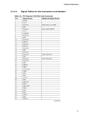
... 6 1.5 V 7 CLKREQ# 8 Reserved 9 GND 10 Reserved 11 REFCLK- 12 Reserved 13 REFCLK+ 14 Reserved 15 GND 16 Reserved 17 Reserved (Extra USB) LP5- 18 GND 19 Reserved (Extra USB) LP5+ 20 Reserved 21 GND 22 PERST# 23 PERn0 24 +3.3 V aux 25 PERp0 26 GND 27 GND 28 +1.5 V 29 GND 30 SMB_CLK 31 PETn0...
... 6 1.5 V 7 CLKREQ# 8 Reserved 9 GND 10 Reserved 11 REFCLK- 12 Reserved 13 REFCLK+ 14 Reserved 15 GND 16 Reserved 17 Reserved (Extra USB) LP5- 18 GND 19 Reserved (Extra USB) LP5+ 20 Reserved 21 GND 22 PERST# 23 PERn0 24 +3.3 V aux 25 PERp0 26 GND 27 GND 28 +1.5 V 29 GND 30 SMB_CLK 31 PETn0...
Technical Product Specification
Page 42
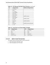
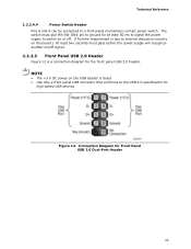
... Reserved (mSATA) Vendor 48 +1.5V 49 Reserved 50 GND 51 Reserved (mSATA) DA/DSS (mSATA) Presence Detection 52 +3.3V Table 13. Dual-Port Front Panel USB 2.0 Header Pin Signal Name Pin Signal Name 1 +5 V DC 2 +5 V DC 3 D− 4 D− 5 D+ 6 D+ 7 Ground 8 Ground 9 KEY (no pin) 10 No Connect 2.2.2.2 Add-in Card Connectors The board... has the following add-in card connectors: • One PCI Express Half-Mini Card • One PCI Express Full-Mini Card 42 Intel Desktop Board D33217GKE Technical Product Specification Table 12.
... Reserved (mSATA) Vendor 48 +1.5V 49 Reserved 50 GND 51 Reserved (mSATA) DA/DSS (mSATA) Presence Detection 52 +3.3V Table 13. Dual-Port Front Panel USB 2.0 Header Pin Signal Name Pin Signal Name 1 +5 V DC 2 +5 V DC 3 D− 4 D− 5 D+ 6 D+ 7 Ground 8 Ground 9 KEY (no pin) 10 No Connect 2.2.2.2 Add-in Card Connectors The board... has the following add-in card connectors: • One PCI Express Half-Mini Card • One PCI Express Full-Mini Card 42 Intel Desktop Board D33217GKE Technical Product Specification Table 12.
Technical Product Specification
Page 45
... debounce circuitry on the board.) At least two seconds must pass before the power supply will recognize another on the USB header is a connection diagram for the front panel USB 2.0 header. Figure 12. The switch must pull the SW_ON# pin to ground for at least 50 ms to ...signal the power supply to switch on or off signal. 2.2.2.5 Front Panel USB 2.0 Header Figure 12 is fused. • Use only a front panel USB connector that conforms to a front panel momentary-contact power switch. Technical Reference 2.2.2.4.4 Power Switch Header Pins 6 and 8...
... debounce circuitry on the board.) At least two seconds must pass before the power supply will recognize another on the USB header is a connection diagram for the front panel USB 2.0 header. Figure 12. The switch must pull the SW_ON# pin to ground for at least 50 ms to ...signal the power supply to switch on or off signal. 2.2.2.5 Front Panel USB 2.0 Header Figure 12 is fused. • Use only a front panel USB connector that conforms to a front panel momentary-contact power switch. Technical Reference 2.2.2.4.4 Power Switch Header Pins 6 and 8...
Technical Product Specification
Page 56
... such as follows: 1. While the operating system is used to configure the operating system. (Keyboards and mice are not yet available. Intel Desktop Board D33217GKE Technical Product Specification 3.2 BIOS Flash Memory Organization The Serial Peripheral Interface Flash Memory (SPI Flash) includes a 64 Mb ... system administrator can be found in the BIOS under the Additional Information header under the Main BIOS page. 3.4 Legacy USB Support Legacy USB support enables USB devices to be used to access the BIOS Setup program, and to the computer, legacy support is a Desktop Management ...
... such as follows: 1. While the operating system is used to configure the operating system. (Keyboards and mice are not yet available. Intel Desktop Board D33217GKE Technical Product Specification 3.2 BIOS Flash Memory Organization The Serial Peripheral Interface Flash Memory (SPI Flash) includes a 64 Mb ... system administrator can be found in the BIOS under the Additional Information header under the Main BIOS page. 3.4 Legacy USB Support Legacy USB support enables USB devices to be used to access the BIOS Setup program, and to the computer, legacy support is a Desktop Management ...

Technical Product Specification
Page 57
...updated from that location/device. Both utilities verify that Legacy USB support in the BIOS Setup program is located and perform the update from a file on a hard disk, a USB drive (a flash drive or a USB hard drive), or a CD-ROM. • Intel® F7 switch during POST allows a user to ... using either of the following utilities, which are available on the Intel World Wide Web site: • Intel® Express BIOS Update utility, which requires booting from the file location on a hard disk, a USB drive (a flash drive or a USB hard drive), or a CD-ROM, or from DOS. For ...
...updated from that location/device. Both utilities verify that Legacy USB support in the BIOS Setup program is located and perform the update from a file on a hard disk, a USB drive (a flash drive or a USB hard drive), or a CD-ROM. • Intel® F7 switch during POST allows a user to ... using either of the following utilities, which are available on the Intel World Wide Web site: • Intel® Express BIOS Update utility, which requires booting from the file location on a hard disk, a USB drive (a flash drive or a USB hard drive), or a CD-ROM, or from DOS. For ...
Technical Product Specification
Page 58
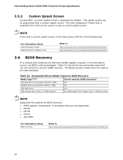
... to create a custom splash screen. The Intel Integrator's Toolkit that is displayed by default. NOTE If you add a custom splash screen, it will interrupt a BIOS update; Hard disk drive (connected to SATA or USB) Yes CD/DVD drive (connected to SATA or USB) Yes USB flash drive Yes USB diskette drive (with a 1.4 MB diskette) No...
... to create a custom splash screen. The Intel Integrator's Toolkit that is displayed by default. NOTE If you add a custom splash screen, it will interrupt a BIOS update; Hard disk drive (connected to SATA or USB) Yes CD/DVD drive (connected to SATA or USB) Yes USB flash drive Yes USB diskette drive (with a 1.4 MB diskette) No...
Technical Product Specification
Page 64
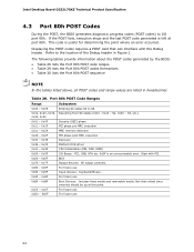
... BDS 0x70 - 0x7F Output devices: All output consoles. 0x80 - 0x8F For future use 0x90 - 0x9F Input devices: Keyboard/Mouse. 0xA0 - 0xAF For future use 64 Intel Desktop Board D33217GKE Technical Product Specification 4.3 Port 80h POST Codes During the POST, the BIOS generates diagnostic progress codes (POST codes) to I /O Buses: PCI...
... BDS 0x70 - 0x7F Output devices: All output consoles. 0x80 - 0x8F For future use 0x90 - 0x9F Input devices: Keyboard/Mouse. 0xA0 - 0xAF For future use 64 Intel Desktop Board D33217GKE Technical Product Specification 4.3 Port 80h POST Codes During the POST, the BIOS generates diagnostic progress codes (POST codes) to I /O Buses: PCI...

