

Technical Product Specification
Page 8
Intel Desktop Board D33217GKE Technical Product Specification 2 Technical Reference 2.1 Memory Resources 35 2.1.1 Addressable Memory 35 2.1.2 Memory Map 37 2.2 Connectors and Headers 37 2.2.1 Back Panel Connectors 38 2.2.2 ... Screen 58 3.6 BIOS Recovery 58 3.7 Boot Options 59 3.7.1 Network Boot 59 3.7.2 Booting Without Attached Devices 59 3.7.3 Changing the Default Boot Device During POST 59 3.8 Hard Disk Drive Password Security Feature 60 3.9 BIOS Security Features 61 4 Error Messages and Blink Codes 4.1 Front-panel Power LED Blink Codes 63 4.2 BIOS Error Messages 63 4.3 Port...
Intel Desktop Board D33217GKE Technical Product Specification 2 Technical Reference 2.1 Memory Resources 35 2.1.1 Addressable Memory 35 2.1.2 Memory Map 37 2.2 Connectors and Headers 37 2.2.1 Back Panel Connectors 38 2.2.2 ... Screen 58 3.6 BIOS Recovery 58 3.7 Boot Options 59 3.7.1 Network Boot 59 3.7.2 Booting Without Attached Devices 59 3.7.3 Changing the Default Boot Device During POST 59 3.8 Hard Disk Drive Password Security Feature 60 3.9 BIOS Security Features 61 4 Error Messages and Blink Codes 4.1 Front-panel Power LED Blink Codes 63 4.2 BIOS Error Messages 63 4.3 Port...

Technical Product Specification
Page 10
... 10. Front Panel Header 43 15. Fan Header Current Capability 50 18. Boot Device Menu Options 59 23. Supervisor and User Password Functions 61 25. Intel Desktop Board D33217GKE Technical Product Specification Tables 1. Feature Summary 11 2. Components Shown in Figure 2 16 4. States for Components 52 20. BIOS Setup Configuration Jumper ... Pressing the Power Switch 30 7. EMC Regulations 75 32. Thermal Considerations for BIOS Recovery 58 22. BIOS Error Messages 63 27. Master Key and User Hard Drive Password Functions 60 24. Port 80h POST Codes 65 29.
... 10. Front Panel Header 43 15. Fan Header Current Capability 50 18. Boot Device Menu Options 59 23. Supervisor and User Password Functions 61 25. Intel Desktop Board D33217GKE Technical Product Specification Tables 1. Feature Summary 11 2. Components Shown in Figure 2 16 4. States for Components 52 20. BIOS Setup Configuration Jumper ... Pressing the Power Switch 30 7. EMC Regulations 75 32. Thermal Considerations for BIOS Recovery 58 22. BIOS Error Messages 63 27. Master Key and User Hard Drive Password Functions 60 24. Port 80h POST Codes 65 29.
Technical Product Specification
Page 14
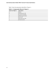
Components Shown in Figure 1. Intel Desktop Board D33217GKE Technical Product Specification Table 3 lists the components identified in Figure 1 Item from Figure 1 A B Description Battery Standby power LED C Processor fan header D Onboard power button E Power LED F Hard Disk Drive LED G Thermal solution 14 Table 3.
Components Shown in Figure 1. Intel Desktop Board D33217GKE Technical Product Specification Table 3 lists the components identified in Figure 1 Item from Figure 1 A B Description Battery Standby power LED C Processor fan header D Onboard power button E Power LED F Hard Disk Drive LED G Thermal solution 14 Table 3.
Technical Product Specification
Page 30
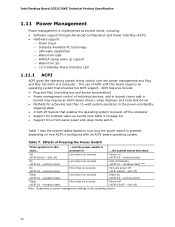
... working state) Less than four seconds Wake-up support Wake from USB WAKE# signal wake-up (ACPI G0 - Intel Desktop Board D33217GKE Technical Product Specification 1.11 Power Management Power management is implemented at several levels, including: • Software support through Advanced ...; Power management control of individual devices, add-in boards (some add-in boards may require an ACPI-aware driver), video displays, and hard disk drives • Methods for achieving less than six seconds Power-off ) Sleep (ACPI G1 - pressed for a front panel power and sleep ...
... working state) Less than four seconds Wake-up support Wake from USB WAKE# signal wake-up (ACPI G0 - Intel Desktop Board D33217GKE Technical Product Specification 1.11 Power Management Power management is implemented at several levels, including: • Software support through Advanced ...; Power management control of individual devices, add-in boards (some add-in boards may require an ACPI-aware driver), video displays, and hard disk drives • Methods for achieving less than six seconds Power-off ) Sleep (ACPI G1 - pressed for a front panel power and sleep ...
Technical Product Specification
Page 44
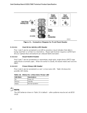
.... 2.2.2.4.3 Power/Sleep LED Header Pins 2 and 4 can be set via BIOS setup. 44 Proper LED function requires a SATA hard drive or optical drive connected to an onboard SATA connector. 2.2.2.4.2 Reset Switch Header Pins 5 and 7 can be connected to a one- or two-color... LED. States for Front Panel Header 2.2.2.4.1 Hard Drive Activity LED Header Pins 1 and 3 can be connected to a momentary single pole, single throw (SPST) type switch that data is default - Table 16. Intel Desktop Board D33217GKE Technical Product Specification Figure 11.
.... 2.2.2.4.3 Power/Sleep LED Header Pins 2 and 4 can be set via BIOS setup. 44 Proper LED function requires a SATA hard drive or optical drive connected to an onboard SATA connector. 2.2.2.4.2 Reset Switch Header Pins 5 and 7 can be connected to a one- or two-color... LED. States for Front Panel Header 2.2.2.4.1 Hard Drive Activity LED Header Pins 1 and 3 can be connected to a momentary single pole, single throw (SPST) type switch that data is default - Table 16. Intel Desktop Board D33217GKE Technical Product Specification Figure 11.

Technical Product Specification
Page 57
Using this utility, the BIOS can be updated from a file on a hard disk, a USB drive (a flash drive or a USB hard drive), or a CD-ROM. • Intel® F7 switch during POST allows a user to prevent accidentally installing an incompatible BIOS. NOTE Review the instructions distributed...Using this utility, the BIOS can be updated from a file on a hard disk, a USB drive (a flash drive or a USB hard drive), or a CD-ROM, or from the file location on the Intel World Wide Web site: • Intel® Express BIOS Update utility, which requires booting from that location/device. ...
Using this utility, the BIOS can be updated from a file on a hard disk, a USB drive (a flash drive or a USB hard drive), or a CD-ROM. • Intel® F7 switch during POST allows a user to prevent accidentally installing an incompatible BIOS. NOTE Review the instructions distributed...Using this utility, the BIOS can be updated from a file on a hard disk, a USB drive (a flash drive or a USB hard drive), or a CD-ROM, or from the file location on the Intel World Wide Web site: • Intel® Express BIOS Update utility, which requires booting from that location/device. ...
Technical Product Specification
Page 58
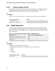
... • ISO 9660 For information about Intel Integrator Toolkit Additional Intel® software tools Refer to http://www.intel.com/support/motherboards/desktop/sb/cs-023360.htm 58 Hard disk drive (connected to SATA or USB) Yes CD/DVD drive (connected to SATA or USB) Yes USB flash drive Yes USB diskette drive (with a 1.4 MB diskette) No (BIOS...
... • ISO 9660 For information about Intel Integrator Toolkit Additional Intel® software tools Refer to http://www.intel.com/support/motherboards/desktop/sb/cs-023360.htm 58 Hard disk drive (connected to SATA or USB) Yes CD/DVD drive (connected to SATA or USB) Yes USB flash drive Yes USB diskette drive (with a 1.4 MB diskette) No (BIOS...

Technical Product Specification
Page 59
... the menu and boots according to be selected as a boot device. The default setting is for the optical drive to be the first boot device, the hard drive second, removable drive third, and the network fourth. 3.7.1 Network Boot The network can choose to boot from the onboard LAN or...this key during POST causes a boot device menu to the boot priority defined through BIOS setup 59 This selection allows booting from a hard drive, optical drive, removable drive, or the network. Error Messages and Beep Codes 3.7 Boot Options In the BIOS Setup program, the user can be displayed. ...
... the menu and boots according to be selected as a boot device. The default setting is for the optical drive to be the first boot device, the hard drive second, removable drive third, and the network fourth. 3.7.1 Network Boot The network can choose to boot from the onboard LAN or...this key during POST causes a boot device menu to the boot priority defined through BIOS setup 59 This selection allows booting from a hard drive, optical drive, removable drive, or the network. Error Messages and Beep Codes 3.7 Boot Options In the BIOS Setup program, the user can be displayed. ...

Technical Product Specification
Page 60
.... Table 24. Intel Desktop Board D33217GKE Technical Product Specification 3.8 Hard Disk Drive Password Security Feature The Hard Disk Drive Password Security feature blocks read and write accesses to the hard disk drive until the Master Key or User hard disk drive password is submitted. For convenient support of setting the Hard Disk Drive Passwords. The Master Key hard disk drive password exists as...
.... Table 24. Intel Desktop Board D33217GKE Technical Product Specification 3.8 Hard Disk Drive Password Security Feature The Hard Disk Drive Password Security feature blocks read and write accesses to the hard disk drive until the Master Key or User hard disk drive password is submitted. For convenient support of setting the Hard Disk Drive Passwords. The Master Key hard disk drive password exists as...
Technical Product Specification
Page 67
... mouse Detecting mouse Detecting presence of mouse Enabling mouse Fixed Media Resetting fixed media Disabling fixed media 0xB2 0xB3 Detecting presence of a fixed media (IDE hard drive detection etc.) Enabling/configuring a fixed media continued 67
... mouse Detecting mouse Detecting presence of mouse Enabling mouse Fixed Media Resetting fixed media Disabling fixed media 0xB2 0xB3 Detecting presence of a fixed media (IDE hard drive detection etc.) Enabling/configuring a fixed media continued 67


