
Technical Product Specification
Page 3
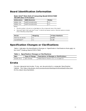
... or Clarifications October 2012 Spec Change Added Note to the Intel® Desktop Board D33217GKE. iii The AA number is found on a small label on page 23. Board Identification Information Basic Intel® Next Unit of the following components: Device Intel Core I3-3217U Intel BD82QS77 Stepping L1 C1 S-Spec Numbers SR0N9 SLI8B Specification Changes...
... or Clarifications October 2012 Spec Change Added Note to the Intel® Desktop Board D33217GKE. iii The AA number is found on a small label on page 23. Board Identification Information Basic Intel® Next Unit of the following components: Device Intel Core I3-3217U Intel BD82QS77 Stepping L1 C1 S-Spec Numbers SR0N9 SLI8B Specification Changes...
Technical Product Specification
Page 6
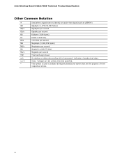
Intel Desktop Board D33217GKE Technical Product Specification Other Common Notation # GB GB/s Gb/s KB Kb kb/s MB MB/s Mb Mb/s TDP xxh x.x V * Used after a signal name to ...
Intel Desktop Board D33217GKE Technical Product Specification Other Common Notation # GB GB/s Gb/s KB Kb kb/s MB MB/s Mb Mb/s TDP xxh x.x V * Used after a signal name to ...

Technical Product Specification
Page 8
Intel Desktop Board D33217GKE Technical Product Specification 2 Technical Reference 2.1 Memory Resources 35 2.1.1 Addressable Memory 35 2.1.2 Memory Map 37 2.2 Connectors and Headers 37 2.2.1 Back Panel Connectors 38 2.2.2 Connectors ...
Intel Desktop Board D33217GKE Technical Product Specification 2 Technical Reference 2.1 Memory Resources 35 2.1.1 Addressable Memory 35 2.1.2 Memory Map 37 2.2 Connectors and Headers 37 2.2.1 Back Panel Connectors 38 2.2.2 Connectors ...

Technical Product Specification
Page 10
... 20. Environmental Specifications 53 21. EMC Regulations 75 32. System Memory Map 37 10. AccepDrives/Media Types for Components 52 19. Regulatory Compliance Marks 79 x Intel Desktop Board D33217GKE Technical Product Specification Tables 1. Thermal Considerations for BIOS Recovery 58 22. Typical Port 80h POST Sequence 69 30. Effects of Pressing the Power...
... 20. Environmental Specifications 53 21. EMC Regulations 75 32. System Memory Map 37 10. AccepDrives/Media Types for Components 52 19. Regulatory Compliance Marks 79 x Intel Desktop Board D33217GKE Technical Product Specification Tables 1. Thermal Considerations for BIOS Recovery 58 22. Typical Port 80h POST Sequence 69 30. Effects of Pressing the Power...
Technical Product Specification
Page 12
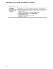
Feature Summary (continued) LAN Support Gigabit (10/100/1000 Mb/s) LAN subsystem using the Intel® 82579V Gigabit Ethernet Controller Hardware Monitor Subsystem Hardware monitoring subsystem, based on a Nuvoton NPCE791C embedded controller, including: • Voltage sense to detect out of range power supply voltages • Thermal sense to detect out of range thermal values • One processor fan header • Fan sense input used to monitor fan activity • Simple fan speed control 12 Intel Desktop Board D33217GKE Technical Product Specification Table 2.
Feature Summary (continued) LAN Support Gigabit (10/100/1000 Mb/s) LAN subsystem using the Intel® 82579V Gigabit Ethernet Controller Hardware Monitor Subsystem Hardware monitoring subsystem, based on a Nuvoton NPCE791C embedded controller, including: • Voltage sense to detect out of range power supply voltages • Thermal sense to detect out of range thermal values • One processor fan header • Fan sense input used to monitor fan activity • Simple fan speed control 12 Intel Desktop Board D33217GKE Technical Product Specification Table 2.
Technical Product Specification
Page 14
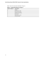
Intel Desktop Board D33217GKE Technical Product Specification Table 3 lists the components identified in Figure 1 Item from Figure 1 A B Description Battery Standby power LED C Processor fan header D Onboard power button E Power LED F Hard Disk Drive LED G Thermal solution 14 Table 3. Components Shown in Figure 1.
Intel Desktop Board D33217GKE Technical Product Specification Table 3 lists the components identified in Figure 1 Item from Figure 1 A B Description Battery Standby power LED C Processor fan header D Onboard power button E Power LED F Hard Disk Drive LED G Thermal solution 14 Table 3. Components Shown in Figure 1.
Technical Product Specification
Page 18
... information BIOS and driver updates Tested memory Integration information http://www.intel.com/products/desktop/chipsets/index.htm http://downloadcenter.intel.com http://www.intel.com/support/motherboards/desktop/sb/CS025414.htm http://www.intel.com/support/go/buildit 1.3 Processor The board has a soldered-down Intel Core i3-3217U processor with Integrated Graphics Technology and integrated memory...
... information BIOS and driver updates Tested memory Integration information http://www.intel.com/products/desktop/chipsets/index.htm http://downloadcenter.intel.com http://www.intel.com/support/motherboards/desktop/sb/CS025414.htm http://www.intel.com/support/go/buildit 1.3 Processor The board has a soldered-down Intel Core i3-3217U processor with Integrated Graphics Technology and integrated memory...
Technical Product Specification
Page 20
... for each channel must be equal. If different speed SO-DIMMs are equal. Tested Memory Refer to: http://support.intel.com/support/motherboards/desktop/sb /CS-025414.htm 1.4.1 Memory Configurations The processor supports the following types of both SO-DIMM channels are used ...slowest memory timing will be used. • Single channel (Asymmetric) mode. This mode is equivalent to : http://www.intel.com/support/motherboards/desktop/sb/cs011965.htm 20 Memory Configuration Examples Refer to single channel bandwidth operation for real world applications. Technology and device width...
... for each channel must be equal. If different speed SO-DIMMs are equal. Tested Memory Refer to: http://support.intel.com/support/motherboards/desktop/sb /CS-025414.htm 1.4.1 Memory Configurations The processor supports the following types of both SO-DIMM channels are used ...slowest memory timing will be used. • Single channel (Asymmetric) mode. This mode is equivalent to : http://www.intel.com/support/motherboards/desktop/sb/cs011965.htm 20 Memory Configuration Examples Refer to single channel bandwidth operation for real world applications. Technology and device width...
Technical Product Specification
Page 22
... buffer is processed in the processor with Direct Media Interface (DMI) interconnect provides interfaces to http://www.intel.com/products/desktop/chipsets/index.htm Chapter 2 1.5.1 Direct Media Interface (DMI) Direct Media Interface (DMI) is the technology for the board...'s I/O paths. Intel Desktop Board D33217GKE Technical Product Specification 1.5 Intel® QS77 Express Chipset Intel QS77 Express Chipset with the display interfaces on the PCH. This high-speed interface integrates advanced priority-based...
... buffer is processed in the processor with Direct Media Interface (DMI) interconnect provides interfaces to http://www.intel.com/products/desktop/chipsets/index.htm Chapter 2 1.5.1 Direct Media Interface (DMI) Direct Media Interface (DMI) is the technology for the board...'s I/O paths. Intel Desktop Board D33217GKE Technical Product Specification 1.5 Intel® QS77 Express Chipset Intel QS77 Express Chipset with the display interfaces on the PCH. This high-speed interface integrates advanced priority-based...
Technical Product Specification
Page 24
... AHCI drivers to the cable. In Native mode, standard PCI Conventional bus resource steering is attached to the latest available by Intel. 24 Microsoft Windows 7 includes the necessary AHCI drivers without the need to install separate AHCI drivers during Microsoft Windows XP installation.... Native mode is reserved for full-speed devices. Use a shielded cable that have an unshielded cable attached to the operating system. Intel Desktop Board D33217GKE Technical Product Specification 1.6.2 USB The board supports seven USB 2.0 ports. The port arrangement is transparent to a USB port ...
... AHCI drivers to the cable. In Native mode, standard PCI Conventional bus resource steering is attached to the latest available by Intel. 24 Microsoft Windows 7 includes the necessary AHCI drivers without the need to install separate AHCI drivers during Microsoft Windows XP installation.... Native mode is reserved for full-speed devices. Use a shielded cable that have an unshielded cable attached to the operating system. Intel Desktop Board D33217GKE Technical Product Specification 1.6.2 USB The board supports seven USB 2.0 ports. The port arrangement is transparent to a USB port ...
Technical Product Specification
Page 26
Intel Desktop Board D33217GKE Technical Product Specification 1.9.1 Intel® 82579V Gigabit Ethernet Controller The Intel 82579V Gigabit Ethernet Controller supports the following features: • 10/100/1000 BASE-T IEEE 802.3 compliant • Energy Efficient Ethernet (EEE) IEEE802.3az ... for active state operation (S0) state SMBUS for host and management traffic (Sx low power state) • Compliant to http://downloadcenter.intel.com 26 For information about Obtaining LAN software and drivers Refer to IEEE 802.3x flow control support • 802.1p and 802.1q •...
Intel Desktop Board D33217GKE Technical Product Specification 1.9.1 Intel® 82579V Gigabit Ethernet Controller The Intel 82579V Gigabit Ethernet Controller supports the following features: • 10/100/1000 BASE-T IEEE 802.3 compliant • Energy Efficient Ethernet (EEE) IEEE802.3az ... for active state operation (S0) state SMBUS for host and management traffic (Sx low power state) • Compliant to http://downloadcenter.intel.com 26 For information about Obtaining LAN software and drivers Refer to IEEE 802.3x flow control support • 802.1p and 802.1q •...
Technical Product Specification
Page 28
For information about Wired for Management (WfM) specification. Intel Desktop Board D33217GKE Technical Product Specification 1.10 Hardware Management Subsystem The hardware management features enable the board to be compatible with the Wired for Management (WfM) Specification Refer to www.intel.com/design/archives/wfm/ 1.10.1 Hardware Monitoring The hardware monitoring and fan control subsystem...
For information about Wired for Management (WfM) specification. Intel Desktop Board D33217GKE Technical Product Specification 1.10 Hardware Management Subsystem The hardware management features enable the board to be compatible with the Wired for Management (WfM) Specification Refer to www.intel.com/design/archives/wfm/ 1.10.1 Hardware Monitoring The hardware monitoring and fan control subsystem...
Technical Product Specification
Page 30
... Power-on (ACPI G0 - Soft off (ACPI G2/G5 - working state) On (ACPI G0 - Soft off ) Less than six seconds Power-off ) Sleep (ACPI G1 - Intel Desktop Board D33217GKE Technical Product Specification 1.11 Power Management Power management is implemented at several levels, including: • Software support through Advanced Configuration and Power Interface...
... Power-on (ACPI G0 - Soft off (ACPI G2/G5 - working state) On (ACPI G0 - Soft off ) Less than six seconds Power-off ) Sleep (ACPI G1 - Intel Desktop Board D33217GKE Technical Product Specification 1.11 Power Management Power management is implemented at several levels, including: • Software support through Advanced Configuration and Power Interface...
Technical Product Specification
Page 32
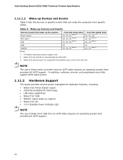
... Wake from this sleep state S3, S4, S5 (Note 1) S3, S4, S5 (Note 1) S3, S4, S5 (Note 1) ...from S4 and S5 is recommended by Microsoft. 3. Intel Desktop Board D33217GKE Technical Product Specification 1.11.1.2 Wake-up Devices and Events Table 9 lists the devices or specific events that provides full ACPI support. In addition...
... Wake from this sleep state S3, S4, S5 (Note 1) S3, S4, S5 (Note 1) S3, S4, S5 (Note 1) ...from S4 and S5 is recommended by Microsoft. 3. Intel Desktop Board D33217GKE Technical Product Specification 1.11.1.2 Wake-up Devices and Events Table 9 lists the devices or specific events that provides full ACPI support. In addition...
Technical Product Specification
Page 34
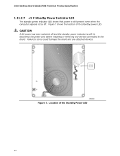
Failure to do so could damage the board and any devices connected to be off. Figure 7 shows the location of the Standby Power LED 34 Figure 7. CAUTION If AC power has been switched off and the standby power indicator is still present even when the computer appears to the board. Intel Desktop Board D33217GKE Technical Product Specification 1.11.2.7 +5 V Standby Power Indicator LED The standby power indicator LED shows that power is still lit, disconnect the power cord before installing or removing any attached devices. Location of the standby power LED.
Failure to do so could damage the board and any devices connected to be off. Figure 7 shows the location of the Standby Power LED 34 Figure 7. CAUTION If AC power has been switched off and the standby power indicator is still present even when the computer appears to the board. Intel Desktop Board D33217GKE Technical Product Specification 1.11.2.7 +5 V Standby Power Indicator LED The standby power indicator LED shows that power is still lit, disconnect the power cord before installing or removing any attached devices. Location of the standby power LED.
Technical Product Specification
Page 38
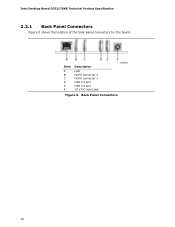
Intel Desktop Board D33217GKE Technical Product Specification 2.2.1 Back Panel Connectors Figure 9 shows the location of the back panel connectors for the board. Item A B C D E F Description LAN HDMI connector 2 HDMI connector 1 USB 2.0 port USB 2.0 port 19 V DC input jack Figure 9. Back Panel Connectors 38
Intel Desktop Board D33217GKE Technical Product Specification 2.2.1 Back Panel Connectors Figure 9 shows the location of the back panel connectors for the board. Item A B C D E F Description LAN HDMI connector 2 HDMI connector 1 USB 2.0 port USB 2.0 port 19 V DC input jack Figure 9. Back Panel Connectors 38
Technical Product Specification
Page 40
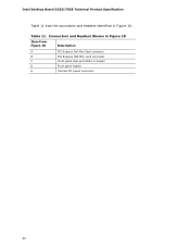
Intel Desktop Board D33217GKE Technical Product Specification Table 11 lists the connectors and headers identified in Figure 10 Item from Figure 10 Description A PCI Express Full-Mini Card connector B PCI Express Half-Mini Card connector C Front panel dual-port USB 2.0 header D Front panel header E Internal DC power connector 40 Connectors and Headers Shown in Figure 10. Table 11.
Intel Desktop Board D33217GKE Technical Product Specification Table 11 lists the connectors and headers identified in Figure 10 Item from Figure 10 Description A PCI Express Full-Mini Card connector B PCI Express Half-Mini Card connector C Front panel dual-port USB 2.0 header D Front panel header E Internal DC power connector 40 Connectors and Headers Shown in Figure 10. Table 11.
Technical Product Specification
Page 42
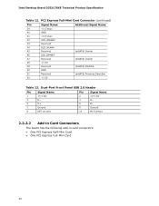
...) Vendor 46 LED_WPAN# 47 Reserved (mSATA) Vendor 48 +1.5V 49 Reserved 50 GND 51 Reserved (mSATA) DA/DSS (mSATA) Presence Detection 52 +3.3V Table 13. Intel Desktop Board D33217GKE Technical Product Specification Table 12. Dual-Port Front Panel USB 2.0 Header Pin Signal Name Pin Signal Name 1 +5 V DC 2 +5 V DC 3 D− 4 D− 5 D+ 6 D+ 7 Ground 8 Ground...
...) Vendor 46 LED_WPAN# 47 Reserved (mSATA) Vendor 48 +1.5V 49 Reserved 50 GND 51 Reserved (mSATA) DA/DSS (mSATA) Presence Detection 52 +3.3V Table 13. Intel Desktop Board D33217GKE Technical Product Specification Table 12. Dual-Port Front Panel USB 2.0 Header Pin Signal Name Pin Signal Name 1 +5 V DC 2 +5 V DC 3 D− 4 D− 5 D+ 6 D+ 7 Ground 8 Ground...
Technical Product Specification
Page 44
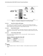
... 4 can be set via BIOS setup. 44 or two-color LED. Table 16. When the switch is being read from or written to a hard drive. Intel Desktop Board D33217GKE Technical Product Specification Figure 11. States for Front Panel Header 2.2.2.4.1 Hard Drive Activity LED Header Pins 1 and 3 can be connected to a one- Connection...
... 4 can be set via BIOS setup. 44 or two-color LED. Table 16. When the switch is being read from or written to a hard drive. Intel Desktop Board D33217GKE Technical Product Specification Figure 11. States for Front Panel Header 2.2.2.4.1 Hard Drive Activity LED Header Pins 1 and 3 can be connected to a one- Connection...
Technical Product Specification
Page 46
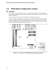
Intel Desktop Board D33217GKE Technical Product Specification 2.3 BIOS Setup Configuration Jumper CAUTION Do not move a jumper with the power on. Figure 13 shows the location of the ...
Intel Desktop Board D33217GKE Technical Product Specification 2.3 BIOS Setup Configuration Jumper CAUTION Do not move a jumper with the power on. Figure 13 shows the location of the ...


