

Technical Product Specification
Page 8
Intel Desktop Board D33217GKE Technical Product Specification 2 Technical Reference 2.1 Memory Resources 35 2.1.1 Addressable Memory 35 2.1.2 Memory Map 37 2.2 Connectors and Headers 37 2.2.1 Back Panel Connectors 38 2.2.2 Connectors and Headers (Bottom 39 2.3 BIOS Setup Configuration Jumper 46 2.4 Mechanical Considerations 48 2.4.1 Form Factor 48 2.5 Electrical Considerations 49 2.5.1 Power Supply...Security Feature 60 3.9 BIOS Security Features 61 4 Error Messages and Blink Codes 4.1 Front-panel Power LED Blink Codes 63 4.2 BIOS Error Messages 63 4.3 Port 80h POST Codes 64 5 ...
Intel Desktop Board D33217GKE Technical Product Specification 2 Technical Reference 2.1 Memory Resources 35 2.1.1 Addressable Memory 35 2.1.2 Memory Map 37 2.2 Connectors and Headers 37 2.2.1 Back Panel Connectors 38 2.2.2 Connectors and Headers (Bottom 39 2.3 BIOS Setup Configuration Jumper 46 2.4 Mechanical Considerations 48 2.4.1 Form Factor 48 2.5 Electrical Considerations 49 2.5.1 Power Supply...Security Feature 60 3.9 BIOS Security Features 61 4 Error Messages and Blink Codes 4.1 Front-panel Power LED Blink Codes 63 4.2 BIOS Error Messages 63 4.3 Port 80h POST Codes 64 5 ...

Technical Product Specification
Page 10
...Safety Standards 71 31. Components Shown in Figure 10 40 11. Dual-Port Front Panel USB 2.0 Header 42 13. 19 V Internal Power Supply Connector 43 14. Front Panel Header 43 15. Supervisor and User Password Functions 61 25. Regulatory Compliance Marks 79 x Supported Memory Configurations... for Components 52 19. Port 80h POST Code Ranges 64 28. Intel Desktop Board D33217GKE Technical Product Specification Tables 1. Feature Summary 11 2. Components Shown in Figure 1 14 3. Effects of Pressing the Power Switch 30 7. PCI Express Full-Mini Card Connector 41 12. BIOS...
...Safety Standards 71 31. Components Shown in Figure 10 40 11. Dual-Port Front Panel USB 2.0 Header 42 13. 19 V Internal Power Supply Connector 43 14. Front Panel Header 43 15. Supervisor and User Password Functions 61 25. Regulatory Compliance Marks 79 x Supported Memory Configurations... for Components 52 19. Port 80h POST Code Ranges 64 28. Intel Desktop Board D33217GKE Technical Product Specification Tables 1. Feature Summary 11 2. Components Shown in Figure 1 14 3. Effects of Pressing the Power Switch 30 7. PCI Express Full-Mini Card Connector 41 12. BIOS...
Technical Product Specification
Page 12
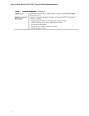
Feature Summary (continued) LAN Support Gigabit (10/100/1000 Mb/s) LAN subsystem using the Intel® 82579V Gigabit Ethernet Controller Hardware Monitor Subsystem Hardware monitoring subsystem, based on a Nuvoton NPCE791C embedded controller, including: • Voltage sense to detect out of range power supply voltages • Thermal sense to detect out of range thermal values • One processor fan header • Fan sense input used to monitor fan activity • Simple fan speed control 12 Intel Desktop Board D33217GKE Technical Product Specification Table 2.
Feature Summary (continued) LAN Support Gigabit (10/100/1000 Mb/s) LAN subsystem using the Intel® 82579V Gigabit Ethernet Controller Hardware Monitor Subsystem Hardware monitoring subsystem, based on a Nuvoton NPCE791C embedded controller, including: • Voltage sense to detect out of range power supply voltages • Thermal sense to detect out of range thermal values • One processor fan header • Fan sense input used to monitor fan activity • Simple fan speed control 12 Intel Desktop Board D33217GKE Technical Product Specification Table 2.
Technical Product Specification
Page 18
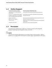
... Specification 1.2 Online Support To find information about... NOTE This board has specific requirements for providing power to Section 2.5.1 on page 49 for information on power supply requirements for Intel Next Unit of Computing Board D33217GKE Visit this board. 18 Intel Next Unit of Computing Board D33217GKE Next Unit of Computing Board Support Available configurations for...
... Specification 1.2 Online Support To find information about... NOTE This board has specific requirements for providing power to Section 2.5.1 on page 49 for information on power supply requirements for Intel Next Unit of Computing Board D33217GKE Visit this board. 18 Intel Next Unit of Computing Board D33217GKE Next Unit of Computing Board Support Available configurations for...
Technical Product Specification
Page 25
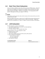
... Controller (10/100/1000 Mb/s) • Intel QS77 Express Chipset • RJ-45 LAN connector with an equivalent one. When the voltage drops below a certain level, the BIOS Setup program settings stored in , the standby current from the power supply extends the life of the LAN subsystem include:...LAN subsystem software For information about LAN software and drivers Refer to ± 13 minutes/year at 25 ºC with 3.3 VSB applied via the power supply 5 V STBY rail. Figure 1 on page 13 shows the location of the battery. 1.9 LAN Subsystem The LAN subsystem consists of three years. ...
... Controller (10/100/1000 Mb/s) • Intel QS77 Express Chipset • RJ-45 LAN connector with an equivalent one. When the voltage drops below a certain level, the BIOS Setup program settings stored in , the standby current from the power supply extends the life of the LAN subsystem include:...LAN subsystem software For information about LAN software and drivers Refer to ± 13 minutes/year at 25 ºC with 3.3 VSB applied via the power supply 5 V STBY rail. Figure 1 on page 13 shows the location of the battery. 1.9 LAN Subsystem The LAN subsystem consists of three years. ...

Technical Product Specification
Page 31
... the various system and power states. D3 - Full power > 30 W Power < 5 W (Note 2) Power < 5 W (Note 2) Power < 5 W (Note 2) G3 - Service can be performed safely. C0 - no power except for a complete description of how devices are not being used can be turned off. no power except for wake-up logic, except when provided by the system chassis' power supply. 2. Devices that are...
... the various system and power states. D3 - Full power > 30 W Power < 5 W (Note 2) Power < 5 W (Note 2) Power < 5 W (Note 2) G3 - Service can be performed safely. C0 - no power except for a complete description of how devices are not being used can be turned off. no power except for wake-up logic, except when provided by the system chassis' power supply. 2. Devices that are...
Technical Product Specification
Page 33
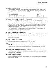
..., or off if single colored.) When signaled by a wake-up the computer. 1.11.2.4 Wake from USB USB bus activity wakes the computer from an AC power failure, the computer returns to enter the ACPI S3 (Suspend-toRAM) sleep-state. NOTE Wake from the S3 state. The LAN subsystem monitors network traffic... When resuming from an ACPI S3 state. Upon detecting a Magic Packet* frame, the LAN subsystem asserts a wake-up signal that can be off (the power supply is off, and the front panel LED is asserted, the computer wakes from an ACPI S3, S4, or S5 state. 1.11.2.6 Wake from an ACPI ...
..., or off if single colored.) When signaled by a wake-up the computer. 1.11.2.4 Wake from USB USB bus activity wakes the computer from an AC power failure, the computer returns to enter the ACPI S3 (Suspend-toRAM) sleep-state. NOTE Wake from the S3 state. The LAN subsystem monitors network traffic... When resuming from an ACPI S3 state. Upon detecting a Magic Packet* frame, the LAN subsystem asserts a wake-up signal that can be off (the power supply is off, and the front panel LED is asserted, the computer wakes from an ACPI S3, S4, or S5 state. 1.11.2.6 Wake from an ACPI ...
Technical Product Specification
Page 43
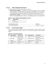
...diagram for the front panel header. Table 15. Technical Reference 2.2.2.3 Power Supply Connectors The board has the following power supply connectors: • External Power Supply - Figure 11 is GND. the board can alternatively be powered through a 19 V DC connector on the back panel. The ... Table 15 lists the signal names of the front panel header. Table 14. 19 V Internal Power Supply Connector Pin Signal Name 1 Ground 2 +19 V (±10%) For information about Power supply considerations Refer to +5V 3 HDD_LED# [Out] Hard disk activity LED 5 GROUND Ground 7 ...
...diagram for the front panel header. Table 15. Technical Reference 2.2.2.3 Power Supply Connectors The board has the following power supply connectors: • External Power Supply - Figure 11 is GND. the board can alternatively be powered through a 19 V DC connector on the back panel. The ... Table 15 lists the signal names of the front panel header. Table 14. 19 V Internal Power Supply Connector Pin Signal Name 1 Ground 2 +19 V (±10%) For information about Power supply considerations Refer to +5V 3 HDD_LED# [Out] Hard disk activity LED 5 GROUND Ground 7 ...
Technical Product Specification
Page 45
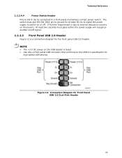
...switch on or off. (The time requirement is due to internal debounce circuitry on the board.) At least two seconds must pass before the power supply will recognize another on the USB header is a connection diagram for the front panel USB 2.0 header. Connection Diagram for Front Panel USB ...2.0 Dual-Port Header 45 NOTE • The +5 V DC power on /off signal. 2.2.2.5 Front Panel USB 2.0 Header Figure 12 is fused. • Use only a front panel USB connector that conforms to a front ...
...switch on or off. (The time requirement is due to internal debounce circuitry on the board.) At least two seconds must pass before the power supply will recognize another on the USB header is a connection diagram for the front panel USB 2.0 header. Connection Diagram for Front Panel USB ...2.0 Dual-Port Header 45 NOTE • The +5 V DC power on /off signal. 2.2.2.5 Front Panel USB 2.0 Header Figure 12 is fused. • Use only a front panel USB connector that conforms to a front ...

Technical Product Specification
Page 49
... this purpose. Simultaneous connection of Computing Board D33217GKE. However, the board also provides an internal 1 x 2 power connector that have an internal power supply. It is the primary power input connector of Intel Next Unit of both external and internal power supply units could result in custom-developed systems that can be attached to the board at any...
... this purpose. Simultaneous connection of Computing Board D33217GKE. However, the board also provides an internal 1 x 2 power connector that have an internal power supply. It is the primary power input connector of Intel Next Unit of both external and internal power supply units could result in custom-developed systems that can be attached to the board at any...
Technical Product Specification
Page 78
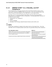
...Product Environmental Assessment Tool (EPEAT) Korea e-Standby Program European Union Energy-related Products Directive 2009 (ErP) Refer to http://www.intel.com/go/energystar http://www.epeat.net/ http://www.kemco.or.kr/new_eng/pg02 /pg02100300.asp http://ec.europa.eu/enterprise... and ErP Compliance The US Department of Computing Board alone does not guarantee Energy Star compliance. Intel Next Unit of Computing Board D33217GKE meets the following program requirements in the definition of an efficient power supply: • Energy Star v5.2, category B • EPEAT* • Korea e-Standby ...
...Product Environmental Assessment Tool (EPEAT) Korea e-Standby Program European Union Energy-related Products Directive 2009 (ErP) Refer to http://www.intel.com/go/energystar http://www.epeat.net/ http://www.kemco.or.kr/new_eng/pg02 /pg02100300.asp http://ec.europa.eu/enterprise... and ErP Compliance The US Department of Computing Board alone does not guarantee Energy Star compliance. Intel Next Unit of Computing Board D33217GKE meets the following program requirements in the definition of an efficient power supply: • Energy Star v5.2, category B • EPEAT* • Korea e-Standby ...


