Product Guide
Page 5
...Passwords 19 Hardware Management 20 Hardware Monitoring and Fan Speed Control 20 Intel® Precision Cooling Technology 20 Chassis Intrusion 20 Power Management 21 Software Support 21 ACPI 21 Hardware Support 21 Power Connectors 21 Fan Headers 22 LAN Wake Capabilities 22 Instantly Available PC ...ENERGY STAR* Capable 25 Onboard Power and Reset Buttons 25 Onboard VR and CPU LEDs 27 Speaker...28 Battery ...28 Real-Time Clock 28 2 Installing and Replacing Desktop Board Components Before You Begin 29 Installation Precautions 30 Prevent Power Supply Overload 30 Observe Safety and ...
...Passwords 19 Hardware Management 20 Hardware Monitoring and Fan Speed Control 20 Intel® Precision Cooling Technology 20 Chassis Intrusion 20 Power Management 21 Software Support 21 ACPI 21 Hardware Support 21 Power Connectors 21 Fan Headers 22 LAN Wake Capabilities 22 Instantly Available PC ...ENERGY STAR* Capable 25 Onboard Power and Reset Buttons 25 Onboard VR and CPU LEDs 27 Speaker...28 Battery ...28 Real-Time Clock 28 2 Installing and Replacing Desktop Board Components Before You Begin 29 Installation Precautions 30 Prevent Power Supply Overload 30 Observe Safety and ...
Product Guide
Page 6
Intel Desktop Board D5400XS Product Guide Installing and Removing the Desktop Board 32 Installing a Processor 33 Installing a Processor 33 Installing a Processor Fan Heat Sink 37 Installing an MCH Heat Sink Fan (Optional 38 Installing and Removing... Consumer IR (CIR) Headers 50 Chassis Intrusion Header 51 Connecting to the Flexible Audio System 52 Connecting Chassis Fan and Power Supply Cables 53 Connecting Chassis Fan Cables 53 Connecting Power Supply Cables 54 Setting the BIOS Configuration Jumper 55 Clearing Passwords 56 Replacing the Battery 57 3 Updating the BIOS Updating the ...
Intel Desktop Board D5400XS Product Guide Installing and Removing the Desktop Board 32 Installing a Processor 33 Installing a Processor 33 Installing a Processor Fan Heat Sink 37 Installing an MCH Heat Sink Fan (Optional 38 Installing and Removing... Consumer IR (CIR) Headers 50 Chassis Intrusion Header 51 Connecting to the Flexible Audio System 52 Connecting Chassis Fan and Power Supply Cables 53 Connecting Chassis Fan Cables 53 Connecting Power Supply Cables 54 Setting the BIOS Configuration Jumper 55 Clearing Passwords 56 Replacing the Battery 57 3 Updating the BIOS Updating the ...
Product Guide
Page 7
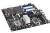
...Chassis and Component Certifications 89 Figures 1. Onboard Power and Reset Buttons 26 6. Desktop Board D5400XS Mounting Screw Hole Locations 32 9. Processor Fan Heat Sink Headers 37 16. Installing a Typical MCH Heat Sink Fan 38 17. Connecting Power Supply Cables 54 27. Remove the Protective Socket Cover... 18 4. DIMM Cooling Fan Header 41 19. Installing a DIMM 39 18. Installing a PCI Express x16 Card 42 20. Desktop Board D5400XS Components 11 2. Remove the Processor from the Protective Processor Cover 35 13. Back Panel Audio Connectors 52 25. Location of the...
...Chassis and Component Certifications 89 Figures 1. Onboard Power and Reset Buttons 26 6. Desktop Board D5400XS Mounting Screw Hole Locations 32 9. Processor Fan Heat Sink Headers 37 16. Installing a Typical MCH Heat Sink Fan 38 17. Connecting Power Supply Cables 54 27. Remove the Protective Socket Cover... 18 4. DIMM Cooling Fan Header 41 19. Installing a DIMM 39 18. Installing a PCI Express x16 Card 42 20. Desktop Board D5400XS Components 11 2. Remove the Processor from the Protective Processor Cover 35 13. Back Panel Audio Connectors 52 25. Location of the...
Product Guide
Page 13
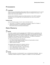
... in Chapter 2 for use an appropriate power supply and/or not connecting the 12 V (2 x 4 pin) power connectors to the Desktop Board may not function properly. Desktop Board D5400XS supports two Intel processors in damage to the board, or the system may result in the LGA771 package. Desktop Board Features Processors CAUTION Failure to use on Desktop Board D5400XS. The Desktop Board features the following: • Four 240...
... in Chapter 2 for use an appropriate power supply and/or not connecting the 12 V (2 x 4 pin) power connectors to the Desktop Board may not function properly. Desktop Board D5400XS supports two Intel processors in damage to the board, or the system may result in the LGA771 package. Desktop Board Features Processors CAUTION Failure to use on Desktop Board D5400XS. The Desktop Board features the following: • Four 240...

Product Guide
Page 20
...and adjusts chassis fan speeds based on the Desktop Board. Intel Desktop Board D5400XS Product Guide Hardware Management The hardware management features of Desktop Board D5400XS enable the board to be connected to detect levels above and below acceptable values • Intel® Precision Cooling Technology fan speed control... the location of power supply voltages to the chassis intrusion header on the internal system temperature. The security feature uses a mechanical switch on the chassis that detects if the chassis cover has been removed. The board has several hardware management...
...and adjusts chassis fan speeds based on the Desktop Board. Intel Desktop Board D5400XS Product Guide Hardware Management The hardware management features of Desktop Board D5400XS enable the board to be connected to detect levels above and below acceptable values • Intel® Precision Cooling Technology fan speed control... the location of power supply voltages to the chassis intrusion header on the internal system temperature. The security feature uses a mechanical switch on the chassis that detects if the chassis cover has been removed. The board has several hardware management...
Product Guide
Page 21
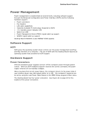
... power supplies can be set by using the Last Power State feature in before power was interrupted (either on page 54 for the location of the power connectors. 21 When an ACPI-enabled computer receives the correct command, the power supply removes all non-standby voltages. Desktop Board Features Power Management Power management is also ENERGY STAR capable. The Desktop Board has four power...
... power supplies can be set by using the Last Power State feature in before power was interrupted (either on page 54 for the location of the power connectors. 21 When an ACPI-enabled computer receives the correct command, the power supply removes all non-standby voltages. Desktop Board Features Power Management Power management is also ENERGY STAR capable. The Desktop Board has four power...

Product Guide
Page 22
... upon detecting a Magic Packet* frame, it asserts a wake-up signal that can damage the power supply. LAN Wake Capabilities CAUTION For LAN wake capabilities, the 5 V standby line for the power supply must be capable of delivering adequate +5 V standby current. Intel Desktop Board D5400XS Product Guide Fan Headers The function/operation of the fans is as follows: • The...
... upon detecting a Magic Packet* frame, it asserts a wake-up signal that can damage the power supply. LAN Wake Capabilities CAUTION For LAN wake capabilities, the 5 V standby line for the power supply must be capable of delivering adequate +5 V standby current. Intel Desktop Board D5400XS Product Guide Fan Headers The function/operation of the fans is as follows: • The...
Product Guide
Page 23
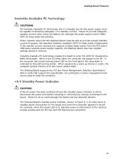
... still present at the memory module sockets and the PCI bus and PCI Express bus connectors. 23 Desktop Board Features Instantly Available PC Technology CAUTIONS For Instantly Available PC technology, the 5 V standby line for the power supply must be able to provide enough standby current to support multiple wake events from the PCI and...
... still present at the memory module sockets and the PCI bus and PCI Express bus connectors. 23 Desktop Board Features Instantly Available PC Technology CAUTIONS For Instantly Available PC technology, the 5 V standby line for the power supply must be able to provide enough standby current to support multiple wake events from the PCI and...
Product Guide
Page 29
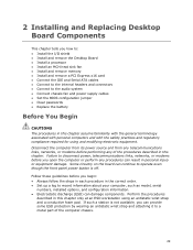
...in personal injury or equipment damage. 2 Installing and Replacing Desktop Board Components This chapter tells you how to: • Install the I/O shield • Install and remove the Desktop Board • Install a processor • Install an MCH heat... sink fan • Install and remove memory • Install and remove a PCI Express x16 card • Connect the IDE and Serial ATA cables • Connect to the internal headers and connectors • Connect to the audio system • Connect chassis fan and power supply...
...in personal injury or equipment damage. 2 Installing and Replacing Desktop Board Components This chapter tells you how to: • Install the I/O shield • Install and remove the Desktop Board • Install a processor • Install an MCH heat... sink fan • Install and remove memory • Install and remove a PCI Express x16 card • Connect the IDE and Serial ATA cables • Connect to the internal headers and connectors • Connect to the audio system • Connect chassis fan and power supply...

Product Guide
Page 30
... devices connected to qualified technical personnel. Intel Desktop Board D5400XS Product Guide Installation Precautions When you install or test the Intel Desktop Board, observe all warnings and cautions that your safety risk and the possibility of noncompliance with the chassis and associated modules. To avoid personal injury, be careful of the power supplies output circuits. If you do not...
... devices connected to qualified technical personnel. Intel Desktop Board D5400XS Product Guide Installation Precautions When you install or test the Intel Desktop Board, observe all warnings and cautions that your safety risk and the possibility of noncompliance with the chassis and associated modules. To avoid personal injury, be careful of the power supplies output circuits. If you do not...
Product Guide
Page 31
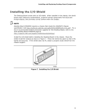
.../SSI%20EEB%20v3-61.pdf). Install the I /O Shield 31 When installed in Figure 7. For a list of recommended chassis and power supplies for this Desktop Board, refer to the Intel Desktop Board D5400XS page at http://support.intel.com/support/motherboards/desktop/. If the shield does not fit, obtain a properly sized shield from dust and foreign objects, and promotes correct airflow within...
.../SSI%20EEB%20v3-61.pdf). Install the I /O Shield 31 When installed in Figure 7. For a list of recommended chassis and power supplies for this Desktop Board, refer to the Intel Desktop Board D5400XS page at http://support.intel.com/support/motherboards/desktop/. If the shield does not fit, obtain a properly sized shield from dust and foreign objects, and promotes correct airflow within...

Product Guide
Page 38
...Attach the fan (Figure 16, A) to the fan mounting bracket (Figure 16, B) using the included MCH heat sink fan mounting bracket. Intel Desktop Board D5400XS Product Guide Installing an MCH Heat Sink Fan (Optional) If your system application requires more MCH cooling than is provided by the MCH passive ...can add a cooling fan to the MCH fan header (Figure 16, D). Attach the fan power connector to the MCH passive heat sink by using the fasteners (Figure 16, A) supplied with Desktop Board D5400XS and must be purchased separately. Installing a Typical MCH Heat Sink Fan 38 This fan mounting ...
...Attach the fan (Figure 16, A) to the fan mounting bracket (Figure 16, B) using the included MCH heat sink fan mounting bracket. Intel Desktop Board D5400XS Product Guide Installing an MCH Heat Sink Fan (Optional) If your system application requires more MCH cooling than is provided by the MCH passive ...can add a cooling fan to the MCH fan header (Figure 16, D). Attach the fan power connector to the MCH passive heat sink by using the fasteners (Figure 16, A) supplied with Desktop Board D5400XS and must be purchased separately. Installing a Typical MCH Heat Sink Fan 38 This fan mounting ...
Product Guide
Page 41
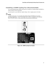
A list of compatible clip-on fans is available on Desktop Board D5400XS to the fan. NOTE A DIMM cooling fan is not included with Desktop Board D5400XS and must be installed on the Desktop Board D5400XS page at http://www.intel.com/products/motherboard/. Use the board's 3-pin DIMM fan header (Figure 18) to supply power to ensure proper memory operation. DIMM Cooling Fan Header 41 Installing and Replacing Desktop Board Components Installing a DIMM Cooling Fan (Recommended) It is recommended that a DIMM cooling fan be purchased separately. Figure 18.
A list of compatible clip-on fans is available on Desktop Board D5400XS to the fan. NOTE A DIMM cooling fan is not included with Desktop Board D5400XS and must be installed on the Desktop Board D5400XS page at http://www.intel.com/products/motherboard/. Use the board's 3-pin DIMM fan header (Figure 18) to supply power to ensure proper memory operation. DIMM Cooling Fan Header 41 Installing and Replacing Desktop Board Components Installing a DIMM Cooling Fan (Recommended) It is recommended that a DIMM cooling fan be purchased separately. Figure 18.

Product Guide
Page 42
Intel Desktop Board D5400XS Product Guide Installing and Removing PCI Express x16 Cards CAUTION When installing a PCI Express card on the Desktop Board, ensure that the card is fully seated in the PCI Express connector before you power on page 29. 2. Installing a PCI Express x16 Card Follow these instructions to the...card retention notch on the card snaps into place around the retention mechanism pin on the over-current protection of the power supply, certain Desktop Board components and/or traces may result across the connector pins. If the card is completely seated in the connector, ...
Intel Desktop Board D5400XS Product Guide Installing and Removing PCI Express x16 Cards CAUTION When installing a PCI Express card on the Desktop Board, ensure that the card is fully seated in the PCI Express connector before you power on page 29. 2. Installing a PCI Express x16 Card Follow these instructions to the...card retention notch on the card snaps into place around the retention mechanism pin on the over-current protection of the power supply, certain Desktop Board components and/or traces may result across the connector pins. If the card is completely seated in the connector, ...

Product Guide
Page 53
Location of the chassis fan headers. Figure 25. Figure 25 shows the location of the Chassis Fan Headers 53 Installing and Replacing Desktop Board Components Connecting Chassis Fan and Power Supply Cables Connecting Chassis Fan Cables Connect chassis fan cables to the 3-pin and 4-pin chassis fan headers on the Desktop Board.
Location of the chassis fan headers. Figure 25. Figure 25 shows the location of the Chassis Fan Headers 53 Installing and Replacing Desktop Board Components Connecting Chassis Fan and Power Supply Cables Connecting Chassis Fan Cables Connect chassis fan cables to the 3-pin and 4-pin chassis fan headers on the Desktop Board.

Product Guide
Page 54
...Intel Desktop Board D5400XS Product Guide Connecting Power Supply Cables CAUTION Failure to use an appropriate power supply and/or not connecting the 12 V (2 x 4 pin) power connectors to the Desktop Board may result in damage to the board or the system may cause damage to do so may not function properly. Figure 26 shows the location of the 1 x 4 power... connector is required with ATX12V power supplies when using PCI Express add-in cards. Connecting Power Supply Cables 54 Failure to the Desktop Board and the add-in cards that can consume 75 ...
...Intel Desktop Board D5400XS Product Guide Connecting Power Supply Cables CAUTION Failure to use an appropriate power supply and/or not connecting the 12 V (2 x 4 pin) power connectors to the Desktop Board may result in damage to the board or the system may cause damage to do so may not function properly. Figure 26 shows the location of the 1 x 4 power... connector is required with ATX12V power supplies when using PCI Express add-in cards. Connecting Power Supply Cables 54 Failure to the Desktop Board and the add-in cards that can consume 75 ...
Product Guide
Page 55
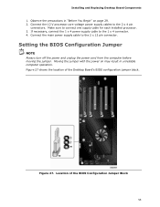
... the 12 V processor core voltage power supply cables to the 2 x 12 pin connector. Connect the main power supply cable to the 2 x 4 pin connectors. Moving the jumper with the power on page 29. 2. Make sure to the 1 x 4 connector. 4. Installing and Replacing Desktop Board Components 1. If necessary, connect the 1 x 4 power supply cable to connect one supply cable for each installed processor. 3. Setting...
... the 12 V processor core voltage power supply cables to the 2 x 12 pin connector. Connect the main power supply cable to the 2 x 4 pin connectors. Moving the jumper with the power on page 29. 2. Make sure to the 1 x 4 connector. 4. Installing and Replacing Desktop Board Components 1. If necessary, connect the 1 x 4 power supply cable to connect one supply cable for each installed processor. 3. Setting...

Product Guide
Page 57
... real-time clock and CMOS memory. The clock is plugged in, the standby current from the power supply extends the life of used batteries must be in accordance with an equivalent one. Installing and Replacing Desktop Board Components 11. When the computer is accurate to ± 13 minutes/year at 25 ºC with an...
... real-time clock and CMOS memory. The clock is plugged in, the standby current from the power supply extends the life of used batteries must be in accordance with an equivalent one. Installing and Replacing Desktop Board Components 11. When the computer is accurate to ± 13 minutes/year at 25 ºC with an...

Product Guide
Page 87
... • Mounting, grounding, and bonding requirements • Keying connectors when mating the wrong connectors could be hazardous If the power supply and other modules or peripherals, as applicable, have passed Class B EMC testing and are not Class B EMC compliant before ... EMC requirements. Ensure Electromagnetic Compatibility (EMC) Compliance Before computer integration, make sure that is household equipment that the power supply and other non-residential environments. Regulatory Compliance Korean Class B statement translation: This is certified to the following when reading...
... • Mounting, grounding, and bonding requirements • Keying connectors when mating the wrong connectors could be hazardous If the power supply and other modules or peripherals, as applicable, have passed Class B EMC testing and are not Class B EMC compliant before ... EMC requirements. Ensure Electromagnetic Compatibility (EMC) Compliance Before computer integration, make sure that is household equipment that the power supply and other non-residential environments. Regulatory Compliance Korean Class B statement translation: This is certified to the following when reading...

Product Guide
Page 89
... chassis and certain components; The Industry Canada statement at the front of Conformity statement to the European EMC directive and Low Voltage directive (as the power supply, peripheral drives, wiring, and cables; Typical product certifications include: In Europe The CE marking signifies compliance with Canadian EMC regulations. 89 Wiring and cables must...
... chassis and certain components; The Industry Canada statement at the front of Conformity statement to the European EMC directive and Low Voltage directive (as the power supply, peripheral drives, wiring, and cables; Typical product certifications include: In Europe The CE marking signifies compliance with Canadian EMC regulations. 89 Wiring and cables must...


