Product Guide
Page 3
... call attention to install the Desktop Board and other environments, such as Information Technology Equipment (I.T.E.) for use in personal computers (PC) for installation in this manual: CAUTION Cautions warn the user about board layout, component installation, BIOS update, and regulatory requirements for general audiences. Intended Audience The Product Guide is not intended for Intel® Desktop Board D5400XS. may not be supported without further evaluation by Intel. Preface This Product...
... call attention to install the Desktop Board and other environments, such as Information Technology Equipment (I.T.E.) for use in personal computers (PC) for installation in this manual: CAUTION Cautions warn the user about board layout, component installation, BIOS update, and regulatory requirements for general audiences. Intended Audience The Product Guide is not intended for Intel® Desktop Board D5400XS. may not be supported without further evaluation by Intel. Preface This Product...
Product Guide
Page 5
... Hardware Monitoring and Fan Speed Control 20 Intel® Precision Cooling Technology 20 Chassis Intrusion 20 Power Management 21 Software Support 21 ACPI 21 Hardware Support 21 Power Connectors 21 Fan Headers 22 LAN Wake Capabilities 22 Instantly Available PC Technology 23 +5 V Standby Power Indicator 23 Wake from USB 25 PME# Signal Wake-up Support 25 WAKE# Signal Wake-up Support 25 ENERGY STAR* Capable 25 Onboard Power and Reset Buttons 25 Onboard VR and CPU LEDs 27 Speaker...28 Battery ...28 Real-Time Clock 28 2 Installing and Replacing Desktop Board...
... Hardware Monitoring and Fan Speed Control 20 Intel® Precision Cooling Technology 20 Chassis Intrusion 20 Power Management 21 Software Support 21 ACPI 21 Hardware Support 21 Power Connectors 21 Fan Headers 22 LAN Wake Capabilities 22 Instantly Available PC Technology 23 +5 V Standby Power Indicator 23 Wake from USB 25 PME# Signal Wake-up Support 25 WAKE# Signal Wake-up Support 25 ENERGY STAR* Capable 25 Onboard Power and Reset Buttons 25 Onboard VR and CPU LEDs 27 Speaker...28 Battery ...28 Real-Time Clock 28 2 Installing and Replacing Desktop Board...
Product Guide
Page 6
... Card 42 Removing a PCI Express x16 Card 43 Installing Multiple Graphics Cards 44 Connecting the IDE Cable 44 Connecting the SATA Cables 46 Connecting to the Internal Headers and Connectors 47 HD Audio Link Header 48 S/PDIF Connector 48 Front Panel Audio Header 49 IEEE 1394a Header 49 Front Panel Header 49 USB 2.0 Headers 50 Consumer IR (CIR) Headers 50 Chassis Intrusion Header 51 Connecting to the Flexible Audio System 52 Connecting Chassis Fan and Power Supply Cables 53 Connecting Chassis Fan Cables 53 Connecting Power Supply Cables 54 Setting the BIOS Configuration Jumper...
... Card 42 Removing a PCI Express x16 Card 43 Installing Multiple Graphics Cards 44 Connecting the IDE Cable 44 Connecting the SATA Cables 46 Connecting to the Internal Headers and Connectors 47 HD Audio Link Header 48 S/PDIF Connector 48 Front Panel Audio Header 49 IEEE 1394a Header 49 Front Panel Header 49 USB 2.0 Headers 50 Consumer IR (CIR) Headers 50 Chassis Intrusion Header 51 Connecting to the Flexible Audio System 52 Connecting Chassis Fan and Power Supply Cables 53 Connecting Chassis Fan Cables 53 Connecting Power Supply Cables 54 Setting the BIOS Configuration Jumper...
Product Guide
Page 7
... of Conformity Statement 78 Product Ecology Statements 79 Recycling Considerations 79 Lead-free 2LI/Pb-free 2LI Board 82 Restriction of the VR and CPU LEDs 27 7. LAN Status LEDs 15 3. Disk Drive Access Indicator 18 4. Desktop Board D5400XS Mounting Screw Hole Locations 32 9. Install the Processor 35 14. Close the Load Plate 36 15. Installing a PCI Express x16 Card 42 20. Removing a PCI Express x16 Card 43 21. Location of the Chassis Fan Headers 53 26. Connecting Power Supply Cables 54 27.
... of Conformity Statement 78 Product Ecology Statements 79 Recycling Considerations 79 Lead-free 2LI/Pb-free 2LI Board 82 Restriction of the VR and CPU LEDs 27 7. LAN Status LEDs 15 3. Disk Drive Access Indicator 18 4. Desktop Board D5400XS Mounting Screw Hole Locations 32 9. Install the Processor 35 14. Close the Load Plate 36 15. Installing a PCI Express x16 Card 42 20. Removing a PCI Express x16 Card 43 21. Location of the Chassis Fan Headers 53 26. Connecting Power Supply Cables 54 27.
Product Guide
Page 9
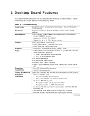
... Dual Inline Memory Module (FBDIMM) sockets • Support for 800/667 MHz SDRAM • Support for multiple PCI Express* graphics cards • Independent multi-streaming 8-channel (7.1) audio and 2-channel audio subsystem, featuring: ― Intel® High Definition Audio interface ― IDT* STAC9274 audio codec • HD Audio Link header • HD Audio front panel header • Onboard 3-pin S/PDIF connector • ADAT* optical interface support from a back panel S/PDIF optical port • Four PCI Express x16 connectors • Two PCI* bus connectors Legacy I/O Support...
... Dual Inline Memory Module (FBDIMM) sockets • Support for 800/667 MHz SDRAM • Support for multiple PCI Express* graphics cards • Independent multi-streaming 8-channel (7.1) audio and 2-channel audio subsystem, featuring: ― Intel® High Definition Audio interface ― IDT* STAC9274 audio codec • HD Audio Link header • HD Audio front panel header • Onboard 3-pin S/PDIF connector • ADAT* optical interface support from a back panel S/PDIF optical port • Four PCI Express x16 connectors • Two PCI* bus connectors Legacy I/O Support...
Product Guide
Page 10
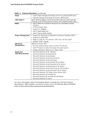
Intel Desktop Board D5400XS Product Guide Table 1. Feature Summary (continued) RAID • Intel® Matrix Storage Technology for the six onboard SATA ports • Marvell* Storage Technology for the two eSATA ports LAN Support Intel® 82573L Gigabit (10/100/1000 Mb/s) Ethernet LAN controller including an RJ-45 back panel connector with integrated status LEDs BIOS • Intel® Platform Innovation Framework for extensible firmware interface • 16 Mb Firmware Hub • Support for SMBIOS • Intel® Rapid...
Intel Desktop Board D5400XS Product Guide Table 1. Feature Summary (continued) RAID • Intel® Matrix Storage Technology for the six onboard SATA ports • Marvell* Storage Technology for the two eSATA ports LAN Support Intel® 82573L Gigabit (10/100/1000 Mb/s) Ethernet LAN controller including an RJ-45 back panel connector with integrated status LEDs BIOS • Intel® Platform Innovation Framework for extensible firmware interface • 16 Mb Firmware Hub • Support for SMBIOS • Intel® Rapid...
Product Guide
Page 12
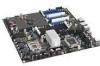
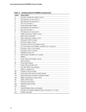
... Processor (CPU 1) fan header Processor (CPU 1) socket FBDIMM sockets (4) Main power connector (2 x 12 pin) Battery Front chassis fan header (3-pin) IDE connector Front panel header Serial ATA connectors (6) Port 80h POST code indicator USB 2.0 headers (2) Chassis intrusion header Front panel CIR receiver (input) header Back panel CIR transmitter (output) header BIOS configuration jumper block IEEE 1394a header Onboard reset button Onboard power button Speaker High Definition Audio Link header Auxiliary PCI Express graphics power connector (1 x 4 pin) S/PDIF connector 12 Intel Desktop Board...
... Processor (CPU 1) fan header Processor (CPU 1) socket FBDIMM sockets (4) Main power connector (2 x 12 pin) Battery Front chassis fan header (3-pin) IDE connector Front panel header Serial ATA connectors (6) Port 80h POST code indicator USB 2.0 headers (2) Chassis intrusion header Front panel CIR receiver (input) header Back panel CIR transmitter (output) header BIOS configuration jumper block IEEE 1394a header Onboard reset button Onboard power button Speaker High Definition Audio Link header Auxiliary PCI Express graphics power connector (1 x 4 pin) S/PDIF connector 12 Intel Desktop Board...
Product Guide
Page 13
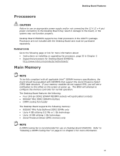
Desktop Board D5400XS supports two Intel processors in Chapter 2 for more information about: • Instructions on installing or upgrading the processor, page 33 in damage to the board, or the system may result in Chapter 2 • Supported processors for use an appropriate power supply and/or not connecting the 12 V (2 x 4 pin) power connectors to the Desktop Board may not function properly. The Desktop Board features the following: • Four 240-pin DDR2 SDRAM FBDIMM sockets with gold...
Desktop Board D5400XS supports two Intel processors in Chapter 2 for more information about: • Instructions on installing or upgrading the processor, page 33 in damage to the board, or the system may result in Chapter 2 • Supported processors for use an appropriate power supply and/or not connecting the 12 V (2 x 4 pin) power connectors to the Desktop Board may not function properly. The Desktop Board features the following: • Four 240-pin DDR2 SDRAM FBDIMM sockets with gold...
Product Guide
Page 14
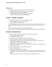
... for front panel audio connectors • HD Audio Link header used for HDMI video cards • S/PDIF connector that can be used for HDMI video cards that do not work with the HD Audio Link header The audio subsystem supports the following features: • Dolby* Home Theater • A signal-to the processors, memory, and the PCI Express bus and the Intel 6321ESB I/O Controller Hub is a centralized controller for Desktop Board D5400XS, http://www.intel.com/products/motherboard/ Intel® 5400 Chipset The Intel 5400 Chipset consists...
... for front panel audio connectors • HD Audio Link header used for HDMI video cards • S/PDIF connector that can be used for HDMI video cards that do not work with the HD Audio Link header The audio subsystem supports the following features: • Dolby* Home Theater • A signal-to the processors, memory, and the PCI Express bus and the Intel 6321ESB I/O Controller Hub is a centralized controller for Desktop Board D5400XS, http://www.intel.com/products/motherboard/ Intel® 5400 Chipset The Intel 5400 Chipset consists...
Product Guide
Page 19
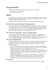
... supervisor or user password was entered. • Setting a user password restricts who can override the auto-configuration options by following expansion capability: • Four PCI Express x16 connectors • Two PCI bus connectors BIOS The BIOS provides the Power-On Self-Test (POST), the BIOS Setup program, and the PCI/PCI Express and IDE auto-configuration utilities. Serial ATA and IDE Auto Configuration If you install a Serial ATA or IDE device (such as a hard drive) in your computer, the auto-configuration utility in the BIOS automatically detects and configures the device for...
... supervisor or user password was entered. • Setting a user password restricts who can override the auto-configuration options by following expansion capability: • Four PCI Express x16 connectors • Two PCI bus connectors BIOS The BIOS provides the Power-On Self-Test (POST), the BIOS Setup program, and the PCI/PCI Express and IDE auto-configuration utilities. Serial ATA and IDE Auto Configuration If you install a Serial ATA or IDE device (such as a hard drive) in your computer, the auto-configuration utility in the BIOS automatically detects and configures the device for...
Product Guide
Page 21
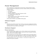
... Advanced Configuration and Power Interface (ACPI) and the following hardware support: • Power connectors • Fan headers • LAN wake capabilities • Instantly Available PC technology (Suspend to the power state it was in the BIOS Setup program's Boot menu. The use of a computer. When an ACPI-enabled computer receives the correct command, the power supply removes all non-standby voltages. The Desktop Board has four power connectors. Software Support ACPI ACPI gives the operating system direct control over the power management and Plug...
... Advanced Configuration and Power Interface (ACPI) and the following hardware support: • Power connectors • Fan headers • LAN wake capabilities • Instantly Available PC technology (Suspend to the power state it was in the BIOS Setup program's Boot menu. The use of a computer. When an ACPI-enabled computer receives the correct command, the power supply removes all non-standby voltages. The Desktop Board has four power connectors. Software Support ACPI ACPI gives the operating system direct control over the power management and Plug...
Product Guide
Page 23
...-in cards that support this green LED is lit, standby power is indicated by a wake-up device or event, the computer quickly returns to be off. The Desktop Board supports the PCI Bus Power Management Interface Specification. While in Figure 4, is lit when there is standby power still present on the front panel, the sleep state is still present at the memory module sockets and the PCI bus and PCI Express bus connectors. 23...
...-in cards that support this green LED is lit, standby power is indicated by a wake-up device or event, the computer quickly returns to be off. The Desktop Board supports the PCI Bus Power Management Interface Specification. While in Figure 4, is lit when there is standby power still present on the front panel, the sleep state is still present at the memory module sockets and the PCI bus and PCI Express bus connectors. 23...
Product Guide
Page 29
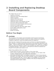
2 Installing and Replacing Desktop Board Components This chapter tells you how to: • Install the I/O shield • Install and remove the Desktop Board • Install a processor • Install an MCH heat sink fan • Install and remove memory • Install and remove a PCI Express x16 card • Connect the IDE and Serial ATA cables • Connect to the internal headers and connectors • Connect to the audio system • Connect chassis fan and power supply cables • Set the BIOS configuration jumper • Clear passwords • Replace the battery Before ...
2 Installing and Replacing Desktop Board Components This chapter tells you how to: • Install the I/O shield • Install and remove the Desktop Board • Install a processor • Install an MCH heat sink fan • Install and remove memory • Install and remove a PCI Express x16 card • Connect the IDE and Serial ATA cables • Connect to the internal headers and connectors • Connect to the audio system • Connect chassis fan and power supply cables • Set the BIOS configuration jumper • Clear passwords • Replace the battery Before ...
Product Guide
Page 44
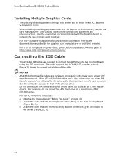
...://www.intel.com/products/motherboard/. Intel Desktop Board D5400XS Product Guide Installing Multiple Graphics Cards The Desktop Board supports technology that of the slowest drive. For a list of the cable. For example, do not connect an ATA hard drive as an ATAPI master device. For more complete installation and configuration information refer to the drives (Figure 21, B). 44 The cable supports the ATA-66/100 transfer protocol. NOTES ATA-66/100 compatible cables are backward compatible with drives using any other IDE...
...://www.intel.com/products/motherboard/. Intel Desktop Board D5400XS Product Guide Installing Multiple Graphics Cards The Desktop Board supports technology that of the slowest drive. For a list of the cable. For example, do not connect an ATA hard drive as an ATAPI master device. For more complete installation and configuration information refer to the drives (Figure 21, B). 44 The cable supports the ATA-66/100 transfer protocol. NOTES ATA-66/100 compatible cables are backward compatible with drives using any other IDE...

Product Guide
Page 56
Intel Desktop Board D5400XS Product Guide The three-pin BIOS jumper block enables all peripheral devices connected to the computer. Configure (2-3) Recovery (None) After the Power-On Self-Test (POST) runs, the BIOS displays the Maintenance Menu. Use this menu to select Clear Passwords. Observe the precautions in "Before You Begin" on the computer, and allow it to be done in the computer, turn on page 29. 2. Remove the computer cover. 4. Replace the cover, plug in the...
Intel Desktop Board D5400XS Product Guide The three-pin BIOS jumper block enables all peripheral devices connected to the computer. Configure (2-3) Recovery (None) After the Power-On Self-Test (POST) runs, the BIOS displays the Maintenance Menu. Use this menu to select Clear Passwords. Observe the precautions in "Before You Begin" on the computer, and allow it to be done in the computer, turn on page 29. 2. Remove the computer cover. 4. Replace the cover, plug in the...
Product Guide
Page 64
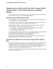
... installed on the Intel World Wide Web site at http://support.intel.com/support/motherboards/desktop. The Iflash BIOS update file contains: • New BIOS file (including the Intel® Management Engine Firmware Image) • Intel® Integrator Toolkit Configuration File (optional) • Intel Flash Memory Update Utility You can use the information in this section to the Desktop Board D5400XS page on the computer's hard drive and without the need to upgrade the BIOS via the Iflash utility. 64 The image uses...
... installed on the Intel World Wide Web site at http://support.intel.com/support/motherboards/desktop. The Iflash BIOS update file contains: • New BIOS file (including the Intel® Management Engine Firmware Image) • Intel® Integrator Toolkit Configuration File (optional) • Intel Flash Memory Update Utility You can use the information in this section to the Desktop Board D5400XS page on the computer's hard drive and without the need to upgrade the BIOS via the Iflash utility. 64 The image uses...
Product Guide
Page 66
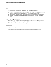
... the USB device and manually update the BIOS. Configure the BIOS or use the F10 option during POST to boot to http://support.intel.com/support/motherboards/desktop/sb/CS-022312.htm. 66 Uncompress the BIOS update file and copy the .BIO file, IFLASH.EXE, and .ITK file (optional) to BIOS size and recovery requirements, a CD-R with the .BIO file in the root directory will interrupt the BIOS update; however, if an interruption occurs, the BIOS could be required. Intel Desktop Board D5400XS Product Guide CAUTION...
... the USB device and manually update the BIOS. Configure the BIOS or use the F10 option during POST to boot to http://support.intel.com/support/motherboards/desktop/sb/CS-022312.htm. 66 Uncompress the BIOS update file and copy the .BIO file, IFLASH.EXE, and .ITK file (optional) to BIOS size and recovery requirements, a CD-R with the .BIO file in the root directory will interrupt the BIOS update; however, if an interruption occurs, the BIOS could be required. Intel Desktop Board D5400XS Product Guide CAUTION...
Product Guide
Page 68
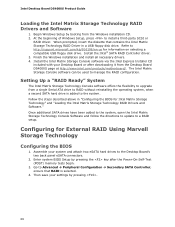
... for External RAID Using Marvell Storage Technology Configuring the BIOS 1. The Intel Matrix Storage Console software can be used to Advanced Peripheral Configuration Secondary SATA Controller; Begin Windows Setup by booting from a single Serial ATA drive to the Desktop Board's two back panel eSATA connectors. 2. Finish the Windows installation and install all necessary drivers. 4. Go to manage the RAID configuration. Then save your system and attach two eSATA hard drives to RAID without reinstalling the operating system, when a second SATA hard drive is selected...
... for External RAID Using Marvell Storage Technology Configuring the BIOS 1. The Intel Matrix Storage Console software can be used to Advanced Peripheral Configuration Secondary SATA Controller; Begin Windows Setup by booting from a single Serial ATA drive to the Desktop Board's two back panel eSATA connectors. 2. Finish the Windows installation and install all necessary drivers. 4. Go to manage the RAID configuration. Then save your system and attach two eSATA hard drives to RAID without reinstalling the operating system, when a second SATA hard drive is selected...

Product Guide
Page 69
... USB floppy disk drive. Exit the Option ROM user interface by booting from the Windows installation CD. 2. Begin Windows Setup by pressing or going to http://support.microsoft.com/kb/916196/en-us for RAID Creating Your RAID Set 1. Install the Marvell 88SE61XX SATA RAID Controller driver. 3. Finally, press to enter the RAID Configuration Utility. Loading the Marvell Storage Technology RAID Drivers and Software 1. Press and enter the RAID Configuration Utility. 2. Refer to the EXIT option in the MAIN MENU. Finish the Windows installation and install all necessary drivers...
... USB floppy disk drive. Exit the Option ROM user interface by booting from the Windows installation CD. 2. Begin Windows Setup by pressing or going to http://support.microsoft.com/kb/916196/en-us for RAID Creating Your RAID Set 1. Install the Marvell 88SE61XX SATA RAID Controller driver. 3. Finally, press to enter the RAID Configuration Utility. Loading the Marvell Storage Technology RAID Drivers and Software 1. Press and enter the RAID Configuration Utility. 2. Refer to the EXIT option in the MAIN MENU. Finish the Windows installation and install all necessary drivers...
Product Guide
Page 75
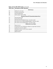
... Drivers E7 Waiting for user input E8 Checking the password E9 Entering BIOS setup EB Calling Legacy Option ROMs Runtime Phase/EFI Operating System Boot F4 Entering Sleep state F5 Exiting Sleep state F8 EFI boot service ExitBootServices( ) has been called F9 EFI runtime service SetVirtualAddressMap( ) has been called FA EFI runtime service ResetSystem( ) has been called PEIMs/Recovery/Wake 30 Wake from S3 31 Crisis Recovery has initiated by software (corrupt Flash memory...
... Drivers E7 Waiting for user input E8 Checking the password E9 Entering BIOS setup EB Calling Legacy Option ROMs Runtime Phase/EFI Operating System Boot F4 Entering Sleep state F5 Exiting Sleep state F8 EFI boot service ExitBootServices( ) has been called F9 EFI runtime service SetVirtualAddressMap( ) has been called FA EFI runtime service ResetSystem( ) has been called PEIMs/Recovery/Wake 30 Wake from S3 31 Crisis Recovery has initiated by software (corrupt Flash memory...


