
English Manual
Page 1
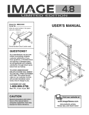
... . MST CAUTION Read all precautions and instructions in the space above for future reference. ¨ USERÕS MANUAL Visit our website at www.imagefitness.com new products, prizes, fitness tips, and much more! As a manufacturer, we will provide immediate assistance, free of charge to providing complete customer satisfaction. Model No. IMBE53990 Serial No. CUSTOMER HOT LINE: 1-800-999...
... . MST CAUTION Read all precautions and instructions in the space above for future reference. ¨ USERÕS MANUAL Visit our website at www.imagefitness.com new products, prizes, fitness tips, and much more! As a manufacturer, we will provide immediate assistance, free of charge to providing complete customer satisfaction. Model No. IMBE53990 Serial No. CUSTOMER HOT LINE: 1-800-999...
English Manual
Page 2
Table of Contents Important Precautions 3 Before You Begin 4 Part Identification Chart 5 Assembly 6 Adjusting the Weight Bench 14 Ordering Replacement Parts Back Cover Limited Warranty Back Cover Note: A Part List/Exploded Drawing is attached in the center of this manual. Remove the Part List/Exploded Drawing before beginning assembly. 2
Table of Contents Important Precautions 3 Before You Begin 4 Part Identification Chart 5 Assembly 6 Adjusting the Weight Bench 14 Ordering Replacement Parts Back Cover Limited Warranty Back Cover Note: A Part List/Exploded Drawing is attached in the center of this manual. Remove the Part List/Exploded Drawing before beginning assembly. 2
English Manual
Page 3
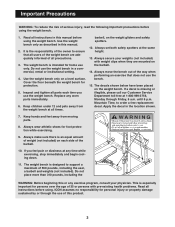
... for home use of the owner to order a free replacement decal. Do not use the bench. 15. Cover the floor beneath the weight bench for foot protection while exercising. 9. until 6 p.m. This is the responsibility of this manual. 2. Read all instructions before using the weight bench. 1. The weight bench is designed to support a maximum of the barbell. 10. Replace any exercise program, consult your weights (not included) with pre-existing health problems. Read all instructions in the location...
... for home use of the owner to order a free replacement decal. Do not use the bench. 15. Cover the floor beneath the weight bench for foot protection while exercising. 9. until 6 p.m. This is the responsibility of this manual. 2. Read all instructions before using the weight bench. 1. The weight bench is designed to support a maximum of the barbell. 10. Replace any exercise program, consult your weights (not included) with pre-existing health problems. Read all instructions in the location...
English Manual
Page 4
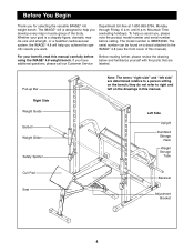
... the specific results you develop every major muscle group of this manual. If you for selecting the versatile IMAGE¨ 4.8 weight bench. Whether your benefit, read this manual carefully before calling. Left Side Upright Dumbbell Storage Rack Weight Storage Tube Curl Pad Seat Backrest Adjustment Bracket 4 until 6 p.m. Department toll-free at 1-800-999-3756, Monday through Friday, 6 a.m. The IMAGE¨ 4.8 is IMBE53990. The model number is...
... the specific results you develop every major muscle group of this manual. If you for selecting the versatile IMAGE¨ 4.8 weight bench. Whether your benefit, read this manual carefully before calling. Left Side Upright Dumbbell Storage Rack Weight Storage Tube Curl Pad Seat Backrest Adjustment Bracket 4 until 6 p.m. Department toll-free at 1-800-999-3756, Monday through Friday, 6 a.m. The IMAGE¨ 4.8 is IMBE53990. The model number is...
English Manual
Page 6
... M10 x 65mm Carriage Bolts (40) up into the indicated holes in the assembly steps may be more convenient if you understand the information in the drawings. Turn the Base Crossbar (20) so the warning decal is designed to do otherwise. ¥ For help identifying small parts, use the PART IDENTIFICATION CHART on the floor. Do not tighten the Nylon Locknuts...
... M10 x 65mm Carriage Bolts (40) up into the indicated holes in the assembly steps may be more convenient if you understand the information in the drawings. Turn the Base Crossbar (20) so the warning decal is designed to do otherwise. ¥ For help identifying small parts, use the PART IDENTIFICATION CHART on the floor. Do not tighten the Nylon Locknuts...
English Manual
Page 7
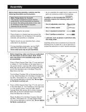
... one of the 3 Uprights (1). Attach the Upright with two M8 Washers (52) and two M8 Nylon Locknuts (54). Do not tighten the Nylon Locknuts yet. Slide the Upright (1) and the Brace (2) onto the M10 x 65mm Carriage Bolts (40) and the M8 x 65mm Carriage Bolts (59) in the right Base (7). Attach the Brace to the Upright with two M10 Nylon...
... one of the 3 Uprights (1). Attach the Upright with two M8 Washers (52) and two M8 Nylon Locknuts (54). Do not tighten the Nylon Locknuts yet. Slide the Upright (1) and the Brace (2) onto the M10 x 65mm Carriage Bolts (40) and the M8 x 65mm Carriage Bolts (59) in the right Base (7). Attach the Brace to the Upright with two M10 Nylon...
English Manual
Page 8
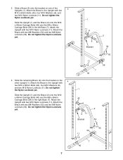
...Attach the Top Crossbar (9) to the right Upright (1) 46 with two M10 x 70mm Bolts (46), a Small Support Plate (16), and two M10 Nylon Locknuts (11). Do not tighten the Nylon Locknuts yet. 11 11 11 Pull-up Bar 9 11 11 1 1 16 46 46 8 5. Press a 25mm Round Inner Cap (51) into the end of 6 the other Weight Storage Tube (21). Press...to the left Brace (2), and the bracket on the Weight Storage Tube (21), the left Upright (1) with two M10 x 70mm Bolts (46), a Small Support Plate (16), and two M10 Nylon Locknuts (11). Attach the Top Crossbar (9) to hold the Top Crossbar (9)...
...Attach the Top Crossbar (9) to the right Upright (1) 46 with two M10 x 70mm Bolts (46), a Small Support Plate (16), and two M10 Nylon Locknuts (11). Do not tighten the Nylon Locknuts yet. 11 11 11 Pull-up Bar 9 11 11 1 1 16 46 46 8 5. Press a 25mm Round Inner Cap (51) into the end of 6 the other Weight Storage Tube (21). Press...to the left Brace (2), and the bracket on the Weight Storage Tube (21), the left Upright (1) with two M10 x 70mm Bolts (46), a Small Support Plate (16), and two M10 Nylon Locknuts (11). Attach the Top Crossbar (9) to hold the Top Crossbar (9)...

English Manual
Page 9
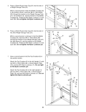
... of the handle and the Left Spotter Hook (65). Secure the Weight Glider to the Barbell with a hand-tightened M8 x 16mm Screw (50). Round tube 29 32 50 29 Round tube 50 29 35 31 11. Press a 25mm Bushing (48) into each end of the welded tube on...Weight Guide away from the Upright (1) as shown in the Locking Bar. 48 34 35 48 9. The Left Weight Glider must be turned as you have correctly identified the left end. Have a second person hold the Locking Bar (34) so that the Left Weight Glider (32) rests on the left end of the round tube. Attach the Weight Guide...
... of the handle and the Left Spotter Hook (65). Secure the Weight Glider to the Barbell with a hand-tightened M8 x 16mm Screw (50). Round tube 29 32 50 29 Round tube 50 29 35 31 11. Press a 25mm Bushing (48) into each end of the welded tube on...Weight Guide away from the Upright (1) as shown in the Locking Bar. 48 34 35 48 9. The Left Weight Glider must be turned as you have correctly identified the left end. Have a second person hold the Locking Bar (34) so that the Left Weight Glider (32) rests on the left end of the round tube. Attach the Weight Guide...
English Manual
Page 10
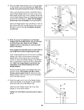
... case you do not need them in steps 9 and 10. Next, tighten the M8 x 16mm Screws used in the same manner. 14. Attach the other Weight Adapter (33) to the bracket on top of the Nylon Locknuts used in the future. Attach the upper end of one of the Weight Guides (18) to the other Upright (1) in the direction shown. Tighten all of the Right...
... case you do not need them in steps 9 and 10. Next, tighten the M8 x 16mm Screws used in the same manner. 14. Attach the other Weight Adapter (33) to the bracket on top of the Nylon Locknuts used in the future. Attach the upper end of one of the Weight Guides (18) to the other Upright (1) in the direction shown. Tighten all of the Right...
English Manual
Page 11
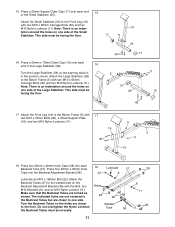
... Square Outer Cap (17) onto each end of the Small Stabilizer (25). Press two 20mm x 40mm Inner Caps (28) into the Backrest Adjustment Bracket (36). 18 Lubricate 27 22 6 Lubricate an M10 x 180mm Bolt (22). The indicated holes are not centered in the position shown. Note: There ... Turn the Large Stabilizer (26) so the warning decal is an indentation around the holes on the Backrest Adjustment Bracket (36) with two M10 x 65mm Carriage Bolts (40) and two M10 Nylon Locknuts (11). Attach the Front Leg (19) to the Front Leg (19) with 17 two M10 x 70mm Bolts (46), a Small Support...
... Square Outer Cap (17) onto each end of the Small Stabilizer (25). Press two 20mm x 40mm Inner Caps (28) into the Backrest Adjustment Bracket (36). 18 Lubricate 27 22 6 Lubricate an M10 x 180mm Bolt (22). The indicated holes are not centered in the position shown. Note: There ... Turn the Large Stabilizer (26) so the warning decal is an indentation around the holes on the Backrest Adjustment Bracket (36) with two M10 x 65mm Carriage Bolts (40) and two M10 Nylon Locknuts (11). Attach the Front Leg (19) to the Front Leg (19) with 17 two M10 x 70mm Bolts (46), a Small Support...
English Manual
Page 12
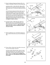
...) into the open 22 end of the Backrest Adjustment Bracket (36). Note: Do not over the 6 bracket on the Bench Frame (5). Attach the Seat Adjustment Bracket (45) to the Backrest Tubes (27) 21 with the Bolt and an M8 Lubricate Nylon Locknut (54). the Seat Adjustment Bracket must pivot easily. 5 21. Next, insert the Bolt through one side of the Seat Support Tube...
...) into the open 22 end of the Backrest Adjustment Bracket (36). Note: Do not over the 6 bracket on the Bench Frame (5). Attach the Seat Adjustment Bracket (45) to the Backrest Tubes (27) 21 with the Bolt and an M8 Lubricate Nylon Locknut (54). the Seat Adjustment Bracket must pivot easily. 5 21. Next, insert the Bolt through one side of the Seat Support Tube...
English Manual
Page 13
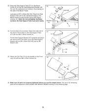
... 25. Turn the Seat (14) as shown. Lubricate Lubricate an M10 x 80mm Bolt (56). Make sure all parts are properly tightened before you use of all remaining parts will be explained in the drawing) on the Seat Support Tube (37) with two M6 x 16mm Screws (3). 24 14 Tilt the Seat Support Bracket (37) upwards and attach the narrow end of the Bench Frame. 23. Attach the wide...
... 25. Turn the Seat (14) as shown. Lubricate Lubricate an M10 x 80mm Bolt (56). Make sure all parts are properly tightened before you use of all remaining parts will be explained in the drawing) on the Seat Support Tube (37) with two M6 x 16mm Screws (3). 24 14 Tilt the Seat Support Bracket (37) upwards and attach the narrow end of the Bench Frame. 23. Attach the wide...

English Manual
Page 14
... your exercise program. Attach weights to a new position and turn the Spotter Hook until the two hooks disengage the slots in the Upright. Raise or lower the Safety Spotter to a new position, grip the handle on the barbell. Replace any worn parts immediately. Inspect and tighten all parts each time you use solvents. WARNING: Always set both Safety Spotters (23, 24) directly under the Weight...
... your exercise program. Attach weights to a new position and turn the Spotter Hook until the two hooks disengage the slots in the Upright. Raise or lower the Safety Spotter to a new position, grip the handle on the barbell. Replace any worn parts immediately. Inspect and tighten all parts each time you use solvents. WARNING: Always set both Safety Spotters (23, 24) directly under the Weight...

English Manual
Page 15
...end of the Seat until the appropriate tab on the Seat Adjustment Bracket (45) engages the welded pin (not shown) on the Seat Adjustment Bracket to the pin. 15 Handle 36 5 Adjustment Bracket Handle 45 14 Pin 5 15 Lower the Seat to the desired position and engage the appropriate tab on the right side of the Bench Frame (5). ...raise the Backrest (15), grip the end of the Backrest with your other hand and pull the Backrest Adjustment Frame free of the tabs on the bracket on the Bench Frame (5). To lower the Backrest (15), grip the end of the Backrest with one of the tabs on the bracket ...
...end of the Seat until the appropriate tab on the Seat Adjustment Bracket (45) engages the welded pin (not shown) on the Seat Adjustment Bracket to the pin. 15 Handle 36 5 Adjustment Bracket Handle 45 14 Pin 5 15 Lower the Seat to the desired position and engage the appropriate tab on the right side of the Bench Frame (5). ...raise the Backrest (15), grip the end of the Backrest with your other hand and pull the Backrest Adjustment Frame free of the tabs on the bracket on the Bench Frame (5). To lower the Backrest (15), grip the end of the Backrest with one of the tabs on the bracket ...
English Manual
Page 16
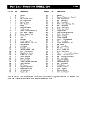
... Weight Guide Front Leg Base Crossbar Weight Storage Tube M10 x 180mm Bolt Right Safety Spotter Left Safety Spotter Small Stabilizer Large Stabilizer Backrest Tube 20mm x 40mm Inner Cap 38mm Bushing M6 Washer Right Weight Glider Left Weight Glider Weight Adapter Locking Bar Key No. Specifications are subject to change without notice. See the back cover of the userÕs manual for information about ordering replacement parts. Part ListÑModel No. IMBE53990 R1299A Key...
... Weight Guide Front Leg Base Crossbar Weight Storage Tube M10 x 180mm Bolt Right Safety Spotter Left Safety Spotter Small Stabilizer Large Stabilizer Backrest Tube 20mm x 40mm Inner Cap 38mm Bushing M6 Washer Right Weight Glider Left Weight Glider Weight Adapter Locking Bar Key No. Specifications are subject to change without notice. See the back cover of the userÕs manual for information about ordering replacement parts. Part ListÑModel No. IMBE53990 R1299A Key...
English Manual
Page 18
... with all freight and other consequential damages of this manual). Limited Warranty ICON Health & Fitness, Inc. (ICON), warrants this product to be prepared to give the following information when calling: ¥ The MODEL NUMBER of the product (IMBE53990) ¥ The NAME of the product (IMAGE¨ 4.8 weight bench) ¥ The SERIAL NUMBER of the product (see the PART LIST and the EXPLODED DRAWING at one of incidental...
... with all freight and other consequential damages of this manual). Limited Warranty ICON Health & Fitness, Inc. (ICON), warrants this product to be prepared to give the following information when calling: ¥ The MODEL NUMBER of the product (IMBE53990) ¥ The NAME of the product (IMAGE¨ 4.8 weight bench) ¥ The SERIAL NUMBER of the product (see the PART LIST and the EXPLODED DRAWING at one of incidental...


