
English Manual
Page 1
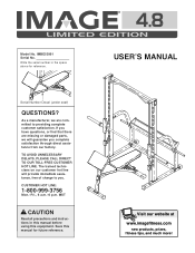
..., PLEASE CALL DIRECT TO OUR TOLL-FREE CUSTOMER HOT LINE. Save this equipment. Model No. Write the serial number in this manual before using this manual for reference. MST CAUTION Read all precautions and instructions in the space above for future reference. ® USER'S MANUAL Visit our website at www.imagefitness.com new products, prizes, fitness tips, and much more! The trained technicians on...
..., PLEASE CALL DIRECT TO OUR TOLL-FREE CUSTOMER HOT LINE. Save this equipment. Model No. Write the serial number in this manual before using this manual for reference. MST CAUTION Read all precautions and instructions in the space above for future reference. ® USER'S MANUAL Visit our website at www.imagefitness.com new products, prizes, fitness tips, and much more! The trained technicians on...
English Manual
Page 2
IMAGE is attached in the center of ICON Health & Fitness, Inc. 2 Table of Contents Important Precautions 3 Before You Begin 4 Part Identification Chart 5 Assembly 6 Adjusting the Weight Bench 14 Ordering Replacement Parts Back Cover Limited Warranty Back Cover Note: A Part List/Exploded Drawing is a registered trademark of this manual. Remove the Part List/Exploded Drawing before beginning assembly.
IMAGE is attached in the center of ICON Health & Fitness, Inc. 2 Table of Contents Important Precautions 3 Before You Begin 4 Part Identification Chart 5 Assembly 6 Adjusting the Weight Bench 14 Ordering Replacement Parts Back Cover Limited Warranty Back Cover Note: A Part List/Exploded Drawing is a registered trademark of this manual. Remove the Part List/Exploded Drawing before beginning assembly.
English Manual
Page 3
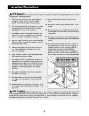
... Friday, 6 a.m. Always move the bench out of 35 or persons with weight clips when they are adequately informed of 560 pounds, including the user, a barbell and weights (not included). If you use the weight bench in this product. 3 This is the responsibility of the owner to order a free replacement decal. Use the weight bench only as described in a commercial, rental or institutional setting. 4. Do not use the weight bench.
... Friday, 6 a.m. Always move the bench out of 35 or persons with weight clips when they are adequately informed of 560 pounds, including the user, a barbell and weights (not included). If you use the weight bench in this product. 3 This is the responsibility of the owner to order a free replacement decal. Use the weight bench only as described in a commercial, rental or institutional setting. 4. Do not use the weight bench.
English Manual
Page 4
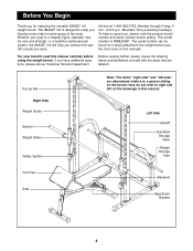
... note the product model number and serial number before using the weight bench. Whether your benefit, read this manual carefully before calling. The model number is a shapely figure, dramatic muscle size and strength, or a healthier cardiovascular system, the IMAGE® 4.8 will help you achieve the specific results you have additional questions, please call our Customer Service Department Before reading further, please review the drawing below...
... note the product model number and serial number before using the weight bench. Whether your benefit, read this manual carefully before calling. The model number is a shapely figure, dramatic muscle size and strength, or a healthier cardiovascular system, the IMAGE® 4.8 will help you achieve the specific results you have additional questions, please call our Customer Service Department Before reading further, please review the drawing below...
English Manual
Page 5
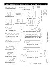
IMBE53991 R1200A M6 x 38mm Bolt (60)-1 M6 x 55mm Bolt (4)-4 M8 x 80mm Bolt (63)-1 M10 x 180mm Bolt (22)-2 M6 Washer (30)-5 M6 x 16mm Screw (3)-4 M10 Washer (6)-14 M8 Nylon Locknut (54)-11 M8 Washer (52)-10 M10 Nylon Locknut (11)-28 M8 x 70mm Bolt (41)-4 M10 x 25mm Button Head Bolt (43)-2 M8 x 65mm Carriage Bolt (59)-4 M10 x 65mm Carriage Bolt (40)-8 M8 x 60mm Bolt (39)-2 M8 x 30mm Bolt (38)-2 M10 x 65mm Bolt (42)-4 M10 x 70mm Bolt (46)-10 M10 x 25mm Bolt (53)-2 M8 x 20mm Bolt (50)-2 M10 x 80mm Bolt (56)-1 M10 x 115mm Bolt (55)-1 5 Part Identification Chart-Model No.
IMBE53991 R1200A M6 x 38mm Bolt (60)-1 M6 x 55mm Bolt (4)-4 M8 x 80mm Bolt (63)-1 M10 x 180mm Bolt (22)-2 M6 Washer (30)-5 M6 x 16mm Screw (3)-4 M10 Washer (6)-14 M8 Nylon Locknut (54)-11 M8 Washer (52)-10 M10 Nylon Locknut (11)-28 M8 x 70mm Bolt (41)-4 M10 x 25mm Button Head Bolt (43)-2 M8 x 65mm Carriage Bolt (59)-4 M10 x 65mm Carriage Bolt (40)-8 M8 x 60mm Bolt (39)-2 M8 x 30mm Bolt (38)-2 M10 x 65mm Bolt (42)-4 M10 x 70mm Bolt (46)-10 M10 x 25mm Bolt (53)-2 M8 x 20mm Bolt (50)-2 M10 x 80mm Bolt (56)-1 M10 x 115mm Bolt (55)-1 5 Part Identification Chart-Model No.
English Manual
Page 6
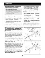
... by anyone. Note: Some parts described in the box above. Turn the Base so the large hole is in the Base. Press a 50mm Square Outer Cap (17) onto each end of a Base (7). This manual is completed. • Tighten all parts as you assemble them, unless instructed to make sure that the weight bench can be pre-assembled. Do not dispose of...
... by anyone. Note: Some parts described in the box above. Turn the Base so the large hole is in the Base. Press a 50mm Square Outer Cap (17) onto each end of a Base (7). This manual is completed. • Tighten all parts as you assemble them, unless instructed to make sure that the weight bench can be pre-assembled. Do not dispose of...

English Manual
Page 7
... M10 x 65mm Carriage Bolts (40) and the M8 x 65mm Carriage Bolts (59) in the right Base (7). Do not tighten the Nylon Locknuts yet. 4. Attach the Brace to the Upright with 4 two M10 x 65mm Bolts (42), four M10 Washers (6), and two M10 Nylon Locknuts (11). Attach the Brace with two ...M10 Nylon Locknuts (11). Attach the Upright with two M8 ...
... M10 x 65mm Carriage Bolts (40) and the M8 x 65mm Carriage Bolts (59) in the right Base (7). Do not tighten the Nylon Locknuts yet. 4. Attach the Brace to the Upright with 4 two M10 x 65mm Bolts (42), four M10 Washers (6), and two M10 Nylon Locknuts (11). Attach the Brace with two ...M10 Nylon Locknuts (11). Attach the Upright with two M8 ...
English Manual
Page 8
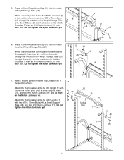
...Press a 25mm Round Inner Cap (51) into the end of 6 the other Weight Storage Tube (21). Have a second person hold the Middle Crossbar (8), insert two M10 x 70mm Bolts (46) through the bracket on the Weight Storage Tube (21), the left Upright (1) with two M10 x 70mm Bolts (46), a Small Support Plate (16), and two M10 Nylon Locknuts (11). Attach... Bolts 8 (46) through the bracket on the Weight Storage Tube (21), the right Brace (2), and the bracket on the Middle Crossbar. Do not tighten the Nylon Locknuts yet. 11 11 11 Pull-up Bar 9 11 11 1 1 16 46 46 8 Do not tighten ...
...Press a 25mm Round Inner Cap (51) into the end of 6 the other Weight Storage Tube (21). Have a second person hold the Middle Crossbar (8), insert two M10 x 70mm Bolts (46) through the bracket on the Weight Storage Tube (21), the left Upright (1) with two M10 x 70mm Bolts (46), a Small Support Plate (16), and two M10 Nylon Locknuts (11). Attach... Bolts 8 (46) through the bracket on the Weight Storage Tube (21), the right Brace (2), and the bracket on the Middle Crossbar. Do not tighten the Nylon Locknuts yet. 11 11 11 Pull-up Bar 9 11 11 1 1 16 46 46 8 Do not tighten ...

English Manual
Page 9
...page 4 to the Barbell with a hand-tightened M8 x 20mm Screw (50). Note: Tilt the Weight Guide away from the Upright (1) as you have correctly identified the left end. Press a 25mm Bushing (48) into the Left Weight Glider, the Left Safety Spotter, and the hole in the Locking Bar. 48 34 35 48 9. Identify the ... into each end of the welded tube on top of 35 the Barbell (35). Attach the Weight Guide (18) to the Barbell with an M8 x 60mm Bolt (39), two M8 Washers (52), and an M8 Nylon Locknut (54). Press a 38mm Bushing (29) into each end of the handle and the Left Spotter ...
...page 4 to the Barbell with a hand-tightened M8 x 20mm Screw (50). Note: Tilt the Weight Guide away from the Upright (1) as you have correctly identified the left end. Press a 25mm Bushing (48) into the Left Weight Glider, the Left Safety Spotter, and the hole in the Locking Bar. 48 34 35 48 9. Identify the ... into each end of the welded tube on top of 35 the Barbell (35). Attach the Weight Guide (18) to the Barbell with an M8 x 60mm Bolt (39), two M8 Washers (52), and an M8 Nylon Locknut (54). Press a 38mm Bushing (29) into each end of the handle and the Left Spotter ...
English Manual
Page 10
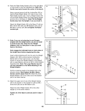
... it . Attach the other Weight Guide (18) to the other Upright (1) in the same manner. 14. Have a second person hold the Locking Bar (34) so that it cannot turn, use the allen wrench to secure the Weight Adapter to the Barbell with the weight bench, you are not planning to use Olympic weights with a Large Washer (44) and an M10 x 25mm Button Head Bolt (43...
... it . Attach the other Weight Guide (18) to the other Upright (1) in the same manner. 14. Have a second person hold the Locking Bar (34) so that it cannot turn, use the allen wrench to secure the Weight Adapter to the Barbell with the weight bench, you are not planning to use Olympic weights with a Large Washer (44) and an M10 x 25mm Button Head Bolt (43...
English Manual
Page 11
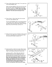
... side. Attach the Backrest Tubes (27) to the Bench Frame (5) with 17 two M10 x 70mm Bolts (46), a Small Support Plate (16), and two M10 Nylon Locknuts (11). 16 46 11 5 11 19 18. Make sure that the Backrest Tubes are closer to the Front Leg (19) with the Bolt, two... over tighten the Nylon Locknut; Press a 50mm Square Outer Cap (17) onto each Backrest Tube (27). Attach the Small Stabilizer (25) to the floor. This side must pivot easily. Press two 20mm x 40mm Inner Caps (28) into the Backrest Adjustment Bracket (36). 18 Lubricate 27 22 6 Lubricate an M10 x 180mm Bolt (22...
... side. Attach the Backrest Tubes (27) to the Bench Frame (5) with 17 two M10 x 70mm Bolts (46), a Small Support Plate (16), and two M10 Nylon Locknuts (11). 16 46 11 5 11 19 18. Make sure that the Backrest Tubes are closer to the Front Leg (19) with the Bolt, two... over tighten the Nylon Locknut; Press a 50mm Square Outer Cap (17) onto each Backrest Tube (27). Attach the Small Stabilizer (25) to the floor. This side must pivot easily. Press two 20mm x 40mm Inner Caps (28) into the Backrest Adjustment Bracket (36). 18 Lubricate 27 22 6 Lubricate an M10 x 180mm Bolt (22...
English Manual
Page 12
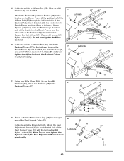
.... the Seat Adjustment Bracket must pivot easily. 21. Press a 25mm x 50mm Inner Cap (58) into the open 22 end of the Seat Support Tube (37) with the Bolt and an M8 Lubricate Nylon Locknut (54). Attach the Backrest Adjustment Bracket (36) to the indicated tube on the Bench Frame, and the other 6 side of the Backrest Adjustment Bracket. Lubricate an M10 x 180mm Bolt (22...
.... the Seat Adjustment Bracket must pivot easily. 21. Press a 25mm x 50mm Inner Cap (58) into the open 22 end of the Seat Support Tube (37) with the Bolt and an M8 Lubricate Nylon Locknut (54). Attach the Backrest Adjustment Bracket (36) to the indicated tube on the Bench Frame, and the other 6 side of the Backrest Adjustment Bracket. Lubricate an M10 x 180mm Bolt (22...
English Manual
Page 13
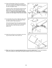
... of the Seat (14) to the Seat Support Tube with the Bolt and an M10 Nylon Locknut (11). Turn the Seat (14) as shown. Lubricate Lubricate an M10 x 80mm Bolt (56). The use of the Bench Frame. Welded Pin 45 56 5 11 24. 23. Attach the wide end of the Seat to the bracket on the side of all parts are properly tightened before you use the weight bench.
... of the Seat (14) to the Seat Support Tube with the Bolt and an M10 Nylon Locknut (11). Turn the Seat (14) as shown. Lubricate Lubricate an M10 x 80mm Bolt (56). The use of the Bench Frame. Welded Pin 45 56 5 11 24. 23. Attach the wide end of the Seat to the bracket on the side of all parts are properly tightened before you use the weight bench.
English Manual
Page 14
...) directly under the 35 32 Weight Gliders (31, 32). 24 USING THE SAFETY SPOTTERS To move during the exercise. Attach weights to which it engages one side of the Spotter Hook (64, 65 [not shown]) and pull the Spotter Hook out of the slot in the Upright (1). Inspect and tighten all parts each side of the Barbell. Turn the Locking Bar until...
...) directly under the 35 32 Weight Gliders (31, 32). 24 USING THE SAFETY SPOTTERS To move during the exercise. Attach weights to which it engages one side of the Spotter Hook (64, 65 [not shown]) and pull the Spotter Hook out of the slot in the Upright (1). Inspect and tighten all parts each side of the Barbell. Turn the Locking Bar until...

English Manual
Page 15
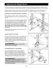
.... To lower the Seat (14), use the handle on the right side of the Bench Frame (5). ADJUSTING THE SEAT To raise the Seat (14), lift the narrow end of the Seat until the appropriate tab on the Seat Adjustment Bracket (45) engages the welded pin (not shown) on the Seat Adjustment Bracket (45... Bench Frame (5). Lower the Seat to disengage the Seat Adjustment Bracket from the pin. Grip the handle (not shown) on the right side of the Backrest Adjustment Frame (36) with your other hand and pull the Backrest Adjustment Frame free of the tabs on the bracket on the Seat Adjustment ...
.... To lower the Seat (14), use the handle on the right side of the Bench Frame (5). ADJUSTING THE SEAT To raise the Seat (14), lift the narrow end of the Seat until the appropriate tab on the Seat Adjustment Bracket (45) engages the welded pin (not shown) on the Seat Adjustment Bracket (45... Bench Frame (5). Lower the Seat to disengage the Seat Adjustment Bracket from the pin. Grip the handle (not shown) on the right side of the Backrest Adjustment Frame (36) with your other hand and pull the Backrest Adjustment Frame free of the tabs on the bracket on the Seat Adjustment ...
English Manual
Page 16
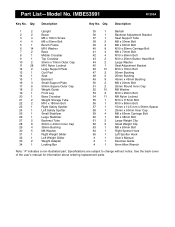
... x 65mm Carriage Bolt 60 1 M6 x 38mm Bolt 61 2 Large Weight Clip 62 2 Small Weight Clip 63 1 M8 x 80mm Bolt 64 1 Right Spotter Hook 65 1 Left Spotter Hook # 1 User's Manual # 1 Exercise Guide # 1 6mm Allen Wrench Note: "#" indicates a non-illustrated part. See the back cover of the user's manual for information about ordering replacement parts. Part List-Model No. Qty. IMBE53991 R1200A Key No. Description Key No. Specifications are subject to change without notice. Qty...
... x 65mm Carriage Bolt 60 1 M6 x 38mm Bolt 61 2 Large Weight Clip 62 2 Small Weight Clip 63 1 M8 x 80mm Bolt 64 1 Right Spotter Hook 65 1 Left Spotter Hook # 1 User's Manual # 1 Exercise Guide # 1 6mm Allen Wrench Note: "#" indicates a non-illustrated part. See the back cover of the user's manual for information about ordering replacement parts. Part List-Model No. Qty. IMBE53991 R1200A Key No. Description Key No. Specifications are subject to change without notice. Qty...
English Manual
Page 17
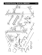
14 13 16 46 11 17 40 52 46 22 22 6 15 27 63 56 37 28 30 28 30 4 6 6 11 11 4 28 36 45 55 58 11 6 30 3 54 60 3 5 11 19 43 10 26 47 44 40 25 33 17 48 35 28 11 57 6 11 18 39 52 10 17 34 61 62 38 16 1 51 46 46 21 42 6 11 9 11 8 38 52 18 11 6 11 11 2 12 41 11 54 11 54 52 54 20 17 7 52 40 54 49 49 59 50 32 50 29 31 11 49 23 33 49 64 49 53 29 49 11 49 24 49 65 29 53 54 52 48 44 43 47 17 40 16 46 1 11 2 6 6 42 21 46 54 52 51 11 17 7 12 41 59 52 39 R1200A Exploded Drawing-Model No. IMBE53991
14 13 16 46 11 17 40 52 46 22 22 6 15 27 63 56 37 28 30 28 30 4 6 6 11 11 4 28 36 45 55 58 11 6 30 3 54 60 3 5 11 19 43 10 26 47 44 40 25 33 17 48 35 28 11 57 6 11 18 39 52 10 17 34 61 62 38 16 1 51 46 46 21 42 6 11 9 11 8 38 52 18 11 6 11 11 2 12 41 11 54 11 54 52 54 20 17 7 52 40 54 49 49 59 50 32 50 29 31 11 49 23 33 49 64 49 53 29 49 11 49 24 49 65 29 53 54 52 48 44 43 47 17 40 16 46 1 11 2 6 6 42 21 46 54 52 51 11 17 7 12 41 59 52 39 R1200A Exploded Drawing-Model No. IMBE53991
English Manual
Page 18
..., or products used as store display models. This warranty gives you . The warranty extended hereunder is limited to replacing or repairing, at ICON's option, the product at the center of this manual). ICON HEALTH & FITNESS, INC., 1500 S. 1000 W., LOGAN, UT 84321-9813 Part No. 172417 R1200A Printed in workmanship and material, under this manual) • The KEY NUMBER and DESCRIPTION of the desired part(s) (see the PART LIST and the...
..., or products used as store display models. This warranty gives you . The warranty extended hereunder is limited to replacing or repairing, at ICON's option, the product at the center of this manual). ICON HEALTH & FITNESS, INC., 1500 S. 1000 W., LOGAN, UT 84321-9813 Part No. 172417 R1200A Printed in workmanship and material, under this manual) • The KEY NUMBER and DESCRIPTION of the desired part(s) (see the PART LIST and the...


