
English Manual
Page 1
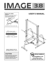
Visit our website at www.imagefitness.com new products, prizes, fitness tips, and much more! Serial Number Decal (under seat) ® USER'S MANUAL SEARS, ROEBUCK AND CO. Model No. 831.159700 Serial No. HOFFMAN ESTATES, IL 60179 CAUTION Read all precautions and instructions in the space above for future reference. Write the serial number in this manual before using this manual for reference. Save this equipment.
Visit our website at www.imagefitness.com new products, prizes, fitness tips, and much more! Serial Number Decal (under seat) ® USER'S MANUAL SEARS, ROEBUCK AND CO. Model No. 831.159700 Serial No. HOFFMAN ESTATES, IL 60179 CAUTION Read all precautions and instructions in the space above for future reference. Write the serial number in this manual before using this manual for reference. Save this equipment.
English Manual
Page 2
Table of Contents Important Precautions 3 Before You Begin 4 Part Identification Chart 5 Assembly 6 Adjusting the Weight Bench 14 Ordering Replacement Parts Back Cover Full 90-Day Warranty Back Cover Note: A Part List/Exploded Drawing is attached in the center of this manual. Remove the Part List/Exploded Drawing before beginning assembly. 2
Table of Contents Important Precautions 3 Before You Begin 4 Part Identification Chart 5 Assembly 6 Adjusting the Weight Bench 14 Ordering Replacement Parts Back Cover Full 90-Day Warranty Back Cover Note: A Part List/Exploded Drawing is attached in the center of this manual. Remove the Part List/Exploded Drawing before beginning assembly. 2
English Manual
Page 3
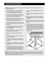
... all users of the weight bench are mounted on the weight bench. The decals shown below have been placed on the barbell. 14. Central Time, to order a free replacement decal. Inspect and tighten all parts each side of the way when performing an exercise that all instructions in the location shown. 7. Replace any time while exercising, stop immediately and begin cooling down. 11. SEARS assumes no...
... all users of the weight bench are mounted on the weight bench. The decals shown below have been placed on the barbell. 14. Central Time, to order a free replacement decal. Inspect and tighten all parts each side of the way when performing an exercise that all instructions in the location shown. 7. Replace any time while exercising, stop immediately and begin cooling down. 11. SEARS assumes no...
English Manual
Page 4
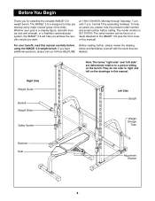
... product model number and serial number before using the IMAGE® 3.8 weight bench. For your goal is a shapely figure, dramatic muscle size and strength, or a healthier cardiovascular system, the IMAGE® 3.8 will help you for selecting the versatile IMAGE® 3.8 weight bench. Whether your benefit, read this manual. The serial number can be found on the bench. The IMAGE® 3.8 is 831.159700. Left Side Upright Weight Storage Tube Backrest Seat Adjustment Bracket...
... product model number and serial number before using the IMAGE® 3.8 weight bench. For your goal is a shapely figure, dramatic muscle size and strength, or a healthier cardiovascular system, the IMAGE® 3.8 will help you for selecting the versatile IMAGE® 3.8 weight bench. Whether your benefit, read this manual. The serial number can be found on the bench. The IMAGE® 3.8 is 831.159700. Left Side Upright Weight Storage Tube Backrest Seat Adjustment Bracket...
English Manual
Page 6
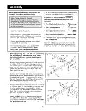
... Carriage Bolts (40) up into the indicated holes in the assembly steps may be assembled successfully by deciding to do otherwise. • For help identifying small parts, use the PART IDENTIFICATION CHART on page 5. Do not tighten the Nylon Locknuts yet. 2. Before beginning, make sure that the weight bench can be pre-assembled. • As you understand the information in the Base. Turn the...
... Carriage Bolts (40) up into the indicated holes in the assembly steps may be assembled successfully by deciding to do otherwise. • For help identifying small parts, use the PART IDENTIFICATION CHART on page 5. Do not tighten the Nylon Locknuts yet. 2. Before beginning, make sure that the weight bench can be pre-assembled. • As you understand the information in the Base. Turn the...

English Manual
Page 7
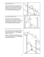
... 1 42 6 2 6 11 Bracket 54 52 59 11 7 40 Do not tighten the Nylon Locknuts yet. 4. Do not tighten the Nylon Locknuts yet. Slide a Brace (2) onto the bracket on the other Upright (1). Do not tighten the Nylon Locknuts yet. Attach the Brace with 4 two M10 x 65mm Bolts (42), four M10 Washers (6), and two M10 Nylon Locknuts (11).
... 1 42 6 2 6 11 Bracket 54 52 59 11 7 40 Do not tighten the Nylon Locknuts yet. 4. Do not tighten the Nylon Locknuts yet. Slide a Brace (2) onto the bracket on the other Upright (1). Do not tighten the Nylon Locknuts yet. Attach the Brace with 4 two M10 x 65mm Bolts (42), four M10 Washers (6), and two M10 Nylon Locknuts (11).
English Manual
Page 8
...) through the bracket on the Weight Storage Tube (21), the left Upright (1) with two M10 x 70mm Bolts (46), a Small Support Plate (16), and two M10 Nylon Locknuts (11). Do not tighten the Nylon Locknuts yet. 51 46 21 46 2 8 46 51 7. Attach the Crossbar (8) to the right Upright (1) with two M10 x 70mm Bolts (46), a Small Support Plate (16), and two...
...) through the bracket on the Weight Storage Tube (21), the left Upright (1) with two M10 x 70mm Bolts (46), a Small Support Plate (16), and two M10 Nylon Locknuts (11). Do not tighten the Nylon Locknuts yet. 51 46 21 46 2 8 46 51 7. Attach the Crossbar (8) to the right Upright (1) with two M10 x 70mm Bolts (46), a Small Support Plate (16), and two...
English Manual
Page 9
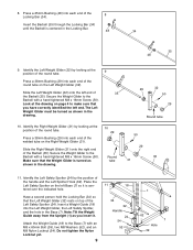
... Press a 38mm Bushing (29) into each end of the Left Safety Spotter (24). Make sure that you insert it is turned as shown in the Locking Bar. 48 34 35 48 9. Identify the Left Safety Spotter (24) by the position of the 8 Locking Bar (34). Note: Tilt the Weight Guide away from the Upright ...the handle and the Left Spotter Hook (62). Attach the Weight Guide (18) to the Barbell with an M8 x 60mm Bolt (39), two M8 Washers (52), and an M8 Nylon Locknut (54). Secure the Weight Glider to the Base (7) with a hand-tightened M8 x 16mm Screw (50). Place the Left Safety Spotter on the...
... Press a 38mm Bushing (29) into each end of the Left Safety Spotter (24). Make sure that you insert it is turned as shown in the Locking Bar. 48 34 35 48 9. Identify the Left Safety Spotter (24) by the position of the 8 Locking Bar (34). Note: Tilt the Weight Guide away from the Upright ...the handle and the Left Spotter Hook (62). Attach the Weight Guide (18) to the Barbell with an M8 x 60mm Bolt (39), two M8 Washers (52), and an M8 Nylon Locknut (54). Secure the Weight Glider to the Base (7) with a hand-tightened M8 x 16mm Screw (50). Place the Left Safety Spotter on the...

English Manual
Page 10
... necessary to tilt the Weight Guide away from the Upright (1) as you do not need them in steps 1 to the Base (7) with a Large Washer (44) and an M10 x 25mm Bolt (43). Next, tighten the M8 x 16mm Screws used in the future. Note: If you need 13 to the bracket on top of the weight bench before beginning this step. Attach the Weight Guide (18) to 14...
... necessary to tilt the Weight Guide away from the Upright (1) as you do not need them in steps 1 to the Base (7) with a Large Washer (44) and an M10 x 25mm Bolt (43). Next, tighten the M8 x 16mm Screws used in the future. Note: If you need 13 to the bracket on top of the weight bench before beginning this step. Attach the Weight Guide (18) to 14...

English Manual
Page 11
...bracket. The indicated holes are not centered in the following way: 17 Lubricate 27 22 6 Holes 28 28 Welded Tube 36 40 28 6 11 28 Lubricate an M10 x 115mm Bolt (55). Do not overtighten the Nylon Locknut; Attach the Large Stabilizer to the floor. Slide the 15mm x 10.2mm...but are closer to the Bench Frame (5) with the Bolt, two M10 Washers (6), and an M10 Nylon Locknut (11). Lubricate an M10 x 180mm Bolt (22). Press two 20mm x 40mm Inner Caps (28) into the Backrest Adjustment Bracket (36). Make sure that the Backrest Tubes are turned as shown. the Backrest ...
...bracket. The indicated holes are not centered in the following way: 17 Lubricate 27 22 6 Holes 28 28 Welded Tube 36 40 28 6 11 28 Lubricate an M10 x 115mm Bolt (55). Do not overtighten the Nylon Locknut; Attach the Large Stabilizer to the floor. Slide the 15mm x 10.2mm...but are closer to the Bench Frame (5) with the Bolt, two M10 Washers (6), and an M10 Nylon Locknut (11). Lubricate an M10 x 180mm Bolt (22). Press two 20mm x 40mm Inner Caps (28) into the Backrest Adjustment Bracket (36). Make sure that the Backrest Tubes are turned as shown. the Backrest ...
English Manual
Page 12
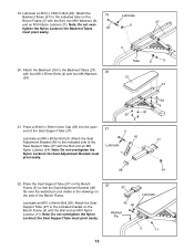
19. Place the Seat Support Tube (37) on the Bench Frame (5) so that the Seat Adjustment Bracket (45) fits over - 6 tighten the Nylon Locknut; the Seat Support Tube must pivot easily. 30 30 4 21 9 45 Lubricate 30 4 37 58 54 22. Attach the Seat Adjustment Bracket (45) to the indicated tube on the Bench Frame (5) with the Bolt, two M10 Washers (6), 27 and an M10 Nylon...
19. Place the Seat Support Tube (37) on the Bench Frame (5) so that the Seat Adjustment Bracket (45) fits over - 6 tighten the Nylon Locknut; the Seat Support Tube must pivot easily. 30 30 4 21 9 45 Lubricate 30 4 37 58 54 22. Attach the Seat Adjustment Bracket (45) to the indicated tube on the Bench Frame (5) with the Bolt, two M10 Washers (6), 27 and an M10 Nylon...
English Manual
Page 13
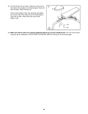
23. The use the weight bench. Make sure that all remaining parts will be explained in ADJUSTING THE WEIGHT BENCH starting on the following page. 13 Turn the Seat (14) as shown. Attach the wide end of the Seat to the bracket on the Seat Support Tube (37) with two M6 x 16mm Screws (3). 23 14 Tilt the Seat Support Tube (37) upwards and attach the narrow end of all parts are properly tightened before you use of the Seat (14) to the Seat Support Tube with an M6 x 38mm Bolt (60) and an M6 37 Washer (30). 30 3 60 24.
23. The use the weight bench. Make sure that all remaining parts will be explained in ADJUSTING THE WEIGHT BENCH starting on the following page. 13 Turn the Seat (14) as shown. Attach the wide end of the Seat to the bracket on the Seat Support Tube (37) with two M6 x 16mm Screws (3). 23 14 Tilt the Seat Support Tube (37) upwards and attach the narrow end of all parts are properly tightened before you use of the Seat (14) to the Seat Support Tube with an M6 x 38mm Bolt (60) and an M6 37 Washer (30). 30 3 60 24.
English Manual
Page 14
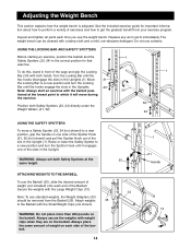
... Safety Spotters (23, 24) directly under the Weight Gliders (31, 32). 24 USING THE SAFETY SPOTTERS To move during the exercise. 32 Position both hands. Adjusting the Weight Bench This section explains how the weight bench is adjusted. The weight bench can be removed from your exercise program. Turn the Locking Bar until the hooks engage the slots in the Uprights. 23 Note: Always start an exercise with the barbell posi...
... Safety Spotters (23, 24) directly under the Weight Gliders (31, 32). 24 USING THE SAFETY SPOTTERS To move during the exercise. 32 Position both hands. Adjusting the Weight Bench This section explains how the weight bench is adjusted. The weight bench can be removed from your exercise program. Turn the Locking Bar until the hooks engage the slots in the Uprights. 23 Note: Always start an exercise with the barbell posi...

English Manual
Page 15
... the bracket on the Bench Frame. Lower the Seat to the desired position and engage the appropriate tab on the Seat Adjustment Bracket to disengage the Seat Adjustment Bracket from the pin. To lower the Seat (14), use the handle on the Seat Adjustment Bracket (45) to the pin. 15 Handle 36 5 Adjustment Bracket Handle 45 14 Pin 5 15 ADJUSTING THE SEAT To raise the Seat (14), lift the...
... the bracket on the Bench Frame. Lower the Seat to the desired position and engage the appropriate tab on the Seat Adjustment Bracket to disengage the Seat Adjustment Bracket from the pin. To lower the Seat (14), use the handle on the Seat Adjustment Bracket (45) to the pin. 15 Handle 36 5 Adjustment Bracket Handle 45 14 Pin 5 15 ADJUSTING THE SEAT To raise the Seat (14), lift the...
English Manual
Page 16
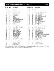
... x 60mm Spacer 58 1 25mm x 50mm Inner Cap 59 4 M8 x 65mm Carriage Bolt 60 1 M6 x 38mm Bolt 61 1 Right Spotter Hook 62 1 Left Spotter Hook # 1 User's Manual # 1 Exercise Guide # 1 6mm Allen Wrench Note: "#" indicates a non-illustrated part. Qty. See the back cover of the user's manual for information about ordering replacement parts. Part List-Model No. 831.159700 R1299A Key No. Qty. Specifications are subject to change without notice. Description...
... x 60mm Spacer 58 1 25mm x 50mm Inner Cap 59 4 M8 x 65mm Carriage Bolt 60 1 M6 x 38mm Bolt 61 1 Right Spotter Hook 62 1 Left Spotter Hook # 1 User's Manual # 1 Exercise Guide # 1 6mm Allen Wrench Note: "#" indicates a non-illustrated part. Qty. See the back cover of the user's manual for information about ordering replacement parts. Part List-Model No. 831.159700 R1299A Key No. Qty. Specifications are subject to change without notice. Description...
English Manual
Page 17
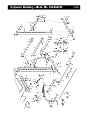
52 38 38 46 16 52 15 28 22 22 6 14 27 30 9 56 37 28 30 4 6 6 11 11 4 28 36 1 51 46 46 21 42 6 11 8 11 8 18 11 45 58 30 3 60 55 11 6 54 11 25 17 40 13 5 10 26 17 40 48 35 19 28 11 57 6 11 18 39 52 10 17 34 47 43 44 33 6 11 11 2 12 41 11 54 11 54 52 54 20 17 7 52 40 54 49 49 59 50 32 50 29 31 54 49 23 33 49 61 49 53 29 49 54 49 24 49 29 62 53 54 52 48 44 43 47 17 40 16 46 1 11 2 6 6 42 21 46 54 52 51 11 17 7 12 41 59 52 39 R1299A Exploded Drawing-Model No. 831.159700
52 38 38 46 16 52 15 28 22 22 6 14 27 30 9 56 37 28 30 4 6 6 11 11 4 28 36 1 51 46 46 21 42 6 11 8 11 8 18 11 45 58 30 3 60 55 11 6 54 11 25 17 40 13 5 10 26 17 40 48 35 19 28 11 57 6 11 18 39 52 10 17 34 47 43 44 33 6 11 11 2 12 41 11 54 11 54 52 54 20 17 7 52 40 54 49 49 59 50 32 50 29 31 54 49 23 33 49 61 49 53 29 49 54 49 24 49 29 62 53 54 52 48 44 43 47 17 40 16 46 1 11 2 6 6 42 21 46 54 52 51 11 17 7 12 41 59 52 39 R1299A Exploded Drawing-Model No. 831.159700
English Manual
Page 18
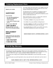
... front cover of this SEARS WEIGHT BENCH EXERCISER, contact the nearest SEARS Service Center throughout the United States and SEARS will repair or replace the WEIGHT BENCH EXERCISER, free of purchase, if failure occurs due to state. REPLACEMENT PARTS If parts become worn and need to be prepared to provide the following tollfree number 1-800-FON-PART (1-800-366-7278) SEARS, ROEBUCK AND CO., HOFFMAN ESTATES, IL 60179 Full 90 Day Warranty...
... front cover of this SEARS WEIGHT BENCH EXERCISER, contact the nearest SEARS Service Center throughout the United States and SEARS will repair or replace the WEIGHT BENCH EXERCISER, free of purchase, if failure occurs due to state. REPLACEMENT PARTS If parts become worn and need to be prepared to provide the following tollfree number 1-800-FON-PART (1-800-366-7278) SEARS, ROEBUCK AND CO., HOFFMAN ESTATES, IL 60179 Full 90 Day Warranty...


