Instruction Manual
Page 3
...place or damage the connectors on a slanted surface or vibrated place). R CAUTION! R CAUTION! ally desire to rain, snow or any problems caused by holding rack mounting handle. Other manufacturers' microphones have two people available to the transceiver. ii R CAUTION! NEVER put the transceiver ...cooling vents on the rear panel. R CAUTION! cohol when cleaning the IC-7700, as benzine or al- This may result in your ears, reduce the volume or discontinue use by Icom Inc., could void your Icom dealer or distributor for long periods. This is not a malfunction or ...
...place or damage the connectors on a slanted surface or vibrated place). R CAUTION! R CAUTION! ally desire to rain, snow or any problems caused by holding rack mounting handle. Other manufacturers' microphones have two people available to the transceiver. ii R CAUTION! NEVER put the transceiver ...cooling vents on the rear panel. R CAUTION! cohol when cleaning the IC-7700, as benzine or al- This may result in your ears, reduce the volume or discontinue use by Icom Inc., could void your Icom dealer or distributor for long periods. This is not a malfunction or ...
Instruction Manual
Page 22
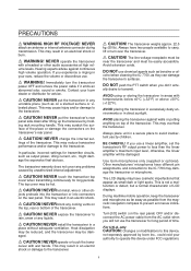
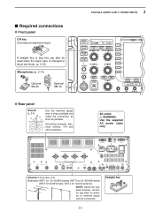
...another Icom CI-V transceiver or receiver. !0 RS-232C TERMINAL [RS-232C] (p. 2-6) Connects an RS-232C cable, D-sub 9-pin to connect the IC-7700 to a PC through a LAN (Local Area Network). u EXTERNAL DISPLAY TERMINAL [EXT-DISPLAY] (p. 2-7) Connects to prevent electrical shocks, TVI, BCI and other problems....TERMINAL [REF I RX ANT OUT IN X-VERTER DC OUT 15V MAX1A EXT METER KEYPAD E X T- Can be used to remotely control the IC-7700 without the optional CT-17, or for transceive operation with a PL-259 plug connector. Deactivate the internal electronic keyer in keyer set mode....
...another Icom CI-V transceiver or receiver. !0 RS-232C TERMINAL [RS-232C] (p. 2-6) Connects an RS-232C cable, D-sub 9-pin to connect the IC-7700 to a PC through a LAN (Local Area Network). u EXTERNAL DISPLAY TERMINAL [EXT-DISPLAY] (p. 2-7) Connects to prevent electrical shocks, TVI, BCI and other problems....TERMINAL [REF I RX ANT OUT IN X-VERTER DC OUT 15V MAX1A EXT METER KEYPAD E X T- Can be used to remotely control the IC-7700 without the optional CT-17, or for transceive operation with a PL-259 plug connector. Deactivate the internal electronic keyer in keyer set mode....
Instruction Manual
Page 30
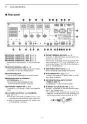
... panel. The transmission line should be connected to a long ground rod. The IC-7700 has an SWR meter to monitor the antenna SWR continuously. ■ USB-Memory connection (USB-Memory: Not supplied by Icom. 2-4 Select antenna(s), such as a well-matched 50 Ω antenna, and...a coaxial cable. 2 INSTALLATION AND CONNECTIONS ■ Grounding To prevent electrical shock, television interference (TVI), broadcast interference (BCI) and other problems, ground the transceiver through the GROUND terminal on and solder it. In this case, an antenna tuner is of -range. For best ...
... panel. The transmission line should be connected to a long ground rod. The IC-7700 has an SWR meter to monitor the antenna SWR continuously. ■ USB-Memory connection (USB-Memory: Not supplied by Icom. 2-4 Select antenna(s), such as a well-matched 50 Ω antenna, and...a coaxial cable. 2 INSTALLATION AND CONNECTIONS ■ Grounding To prevent electrical shock, television interference (TVI), broadcast interference (BCI) and other problems, ground the transceiver through the GROUND terminal on and solder it. In this case, an antenna tuner is of -range. For best ...
Instruction Manual
Page 31
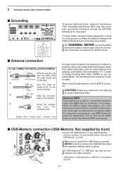
... I RX ANT OUT IN X-VERTER DC OUT 15V MAX1A EXT METER KEYPAD E X T- Straight key 2-5 ANT 1 ANT 2 ANT 3 ANT 4 E X T- Grounding prevents electrical shocks, TVI and other problems. AC outlet R WARNING: Use the supplied AC power cable only. A straight key or bug key can also be used when the keyer type is connected.
... I RX ANT OUT IN X-VERTER DC OUT 15V MAX1A EXT METER KEYPAD E X T- Straight key 2-5 ANT 1 ANT 2 ANT 3 ANT 4 E X T- Grounding prevents electrical shocks, TVI and other problems. AC outlet R WARNING: Use the supplied AC power cable only. A straight key or bug key can also be used when the keyer type is connected.
Instruction Manual
Page 182
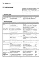
...RIT or ∂TX function is turned OFF. when the [POWER] switch • The internal power supply is activated. D Transmit and receive PROBLEM No sounds from speaker. POSSIBLE CAUSE the • Volume level is too low. • The squelch is closed. • The transceiver is ...." to manually p. 10-6 tune the antenna. • Push [ATT] (MF4) several times to locate the cause of a problem or solve it through the use of an external unit, if connected. p. 2-5 • Turn the internal power supply ON. If you nearest Icom Dealer or Service Center. wrong. breaker.
...RIT or ∂TX function is turned OFF. when the [POWER] switch • The internal power supply is activated. D Transmit and receive PROBLEM No sounds from speaker. POSSIBLE CAUSE the • Volume level is too low. • The squelch is closed. • The transceiver is ...." to manually p. 10-6 tune the antenna. • Push [ATT] (MF4) several times to locate the cause of a problem or solve it through the use of an external unit, if connected. p. 2-5 • Turn the internal power supply ON. If you nearest Icom Dealer or Service Center. wrong. breaker.
Instruction Manual
Page 183
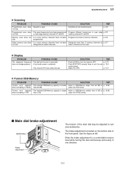
...tension of the front panel. not stop. • Set [SQL] to turn the function OFF. p. 13-7 D Format USB-Memory PROBLEM POSSIBLE CAUSE SOLUTION REF. select the FAT format. start designated as p. 9-7 not start programmed. Format error appears • The inserted USB...and evenly in FAT than 2 memory channels as select channels. Slide the brake adjustment to suit your preference. MAINTENANCE 13 D Scanning PROBLEM POSSIBLE CAUSE SOLUTION REF. Memory scan does not • 2 or more memory channels have been programmed • Program different frequencies ...
...tension of the front panel. not stop. • Set [SQL] to turn the function OFF. p. 13-7 D Format USB-Memory PROBLEM POSSIBLE CAUSE SOLUTION REF. select the FAT format. start designated as p. 9-7 not start programmed. Format error appears • The inserted USB...and evenly in FAT than 2 memory channels as select channels. Slide the brake adjustment to suit your preference. MAINTENANCE 13 D Scanning PROBLEM POSSIBLE CAUSE SOLUTION REF. Memory scan does not • 2 or more memory channels have been programmed • Program different frequencies ...


