Instruction Manual
Page 37
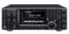
.... 1 A Connected in use, the CW side tone or beep tone decreases from the fixed level when the [AF] control is in parallel with ACC 2 pin 3. 4 MOD Modulator input. ACC 2 2 45 1 3 67 PIN No. Input voltage : More than 10 mA 2 GND Same as ACC 1 pin 2. 3 SEND Same as ACC 1 pin 8. 6 TRV Activates...
.... 1 A Connected in use, the CW side tone or beep tone decreases from the fixed level when the [AF] control is in parallel with ACC 2 pin 3. 4 MOD Modulator input. ACC 2 2 45 1 3 67 PIN No. Input voltage : More than 10 mA 2 GND Same as ACC 1 pin 2. 3 SEND Same as ACC 1 pin 8. 6 TRV Activates...
Instruction Manual
Page 161
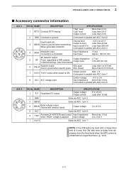
...Output Level Sets the desired audio output level, output from [ACC1], within 0 to 100% in 1% steps. (default: 50%) 50% DATA OFF MOD Selects the desired connector(s) for modulation input when data mode is in 1% steps. 50% • Outputs approx. 200 mV at 50% (default) setting....(pin 4). • MIC,ACC : Use the signals from [MIC] and [ACC1] (pin 4). (default) • S/P DIF : Use the signals from [S/P DIF]. DATA2 MOD Selects the desired connector(s) for modulation from [S/P DIF]. 12-7 S/PDIF Output Level Sets the desired output level of [S/P DIF], within 0 to 100% in use . ACC...
...Output Level Sets the desired audio output level, output from [ACC1], within 0 to 100% in 1% steps. (default: 50%) 50% DATA OFF MOD Selects the desired connector(s) for modulation input when data mode is in 1% steps. 50% • Outputs approx. 200 mV at 50% (default) setting....(pin 4). • MIC,ACC : Use the signals from [MIC] and [ACC1] (pin 4). (default) • S/P DIF : Use the signals from [S/P DIF]. DATA2 MOD Selects the desired connector(s) for modulation from [S/P DIF]. 12-7 S/PDIF Output Level Sets the desired output level of [S/P DIF], within 0 to 100% in use . ACC...
Instruction Manual
Page 162
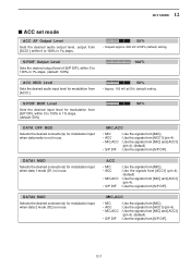
... of the final am- Select the suitable relay type when connecting a nonIcom linear amplifier. plifier MOSFETs. 12 SET MODE ■ ACC set mode (continued) DATA3 MOD Selects the desired connector(s) for modulation input when data 3 mode (D3) is in 1% steps. 50% • Approx. 2.5 V at 50% (default) setting for full-scale indication...
... of the final am- Select the suitable relay type when connecting a nonIcom linear amplifier. plifier MOSFETs. 12 SET MODE ■ ACC set mode (continued) DATA3 MOD Selects the desired connector(s) for modulation input when data 3 mode (D3) is in 1% steps. 50% • Approx. 2.5 V at 50% (default) setting for full-scale indication...
Instruction Manual
Page 193
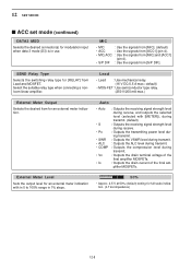
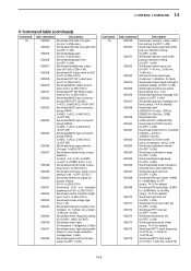
...S/P DIF output level (0=0% to 255=100%) Send/read MOD output level to ACC (0=0% to 255=100%) Send/read S/P DIF MOD output level (0=0% to 255=100%) Send/read MOD input connector during DATA OFF (0=MIC; 1=ACC; 2=MIC/ACC; 3=S/P DIF) Send/read MOD input connector during DATA1 (0=MIC; 1=ACC; 2=MIC/ACC...; 3=S/P DIF) Send/read MOD input connector during DATA2 (0=MIC; 1=ACC; 2=MIC/ACC; 3=S/P DIF) Send/read MOD input connector during DATA3 (0=MIC; 1=ACC; 2=MIC/ACC; 3=S/P DIF) Send/read...
...S/P DIF output level (0=0% to 255=100%) Send/read MOD output level to ACC (0=0% to 255=100%) Send/read S/P DIF MOD output level (0=0% to 255=100%) Send/read MOD input connector during DATA OFF (0=MIC; 1=ACC; 2=MIC/ACC; 3=S/P DIF) Send/read MOD input connector during DATA1 (0=MIC; 1=ACC; 2=MIC/ACC...; 3=S/P DIF) Send/read MOD input connector during DATA2 (0=MIC; 1=ACC; 2=MIC/ACC; 3=S/P DIF) Send/read MOD input connector during DATA3 (0=MIC; 1=ACC; 2=MIC/ACC; 3=S/P DIF) Send/read...


