Get support for Icom IC-718

Icom IC-718 Support Question

Icom IC-718 Support Question

Find answers below for this question about Icom IC-718.
Need a Icom IC-718 manual? We have 1 online manual for this item!
Question posted by gordonsau on June 29th, 2021

Remove 11 Mtr Mods

I recently purchased an Ic718 with the 27 Mhz mods installed. To use any frequency you have to put it in via the keyboard and then it shows up on the display. The display does work . I cannot dial up any frequency whatsoever. How can I remove the 11 Mtr band and have the radio put back to normal. Would it take a Tec to be able to do this, or could something be done to bring the display back. It is the display that interests me more. Thanks for readingGordon VK4KGS

Current Answers

Answer #1: Posted by Odin on June 30th, 2021 9:57 AM
This answer was accepted by the poster of the original question.
Odin

Member since:
April 10th, 2010

Points: 41,236,700
1,110
points
Try resetting your CPU. While your transceiver is off, hold down the UP & DOWN buttons simultaneously and then turn the transceiver back on. Now it should be reset to the factory default settings.i

If the issue persists or if you require further advice, you may want to consult the company: use the contact information at https://www.contacthelp.com/icom.


Hope this is useful. Please don't forget to click the Accept This Answer button if you do accept it. My aim is to provide reliable helpful answers, not just a lot of them. See https://www.helpowl.com/profile/Odin.
Answer #2: Posted by SonuKumar on July 4th, 2021 5:36 AM
SonuKumar

Member since:
May 9th, 2021

Points: 16,604,580
100
points
How do I reset my ICOM radio?

IC-481H - Full reset: Hold [SET] & [SPCH] buttons and turn the radio on. Partial reset: hold [SPCH] button and turn the radio on. IC-706 - Hold [UP] & [DOWN] buttons and turn the radio on.

How do you unlock ICOM?

PRESS AND HOLD to lock. PRESS AND HOLD to unlock.

How do I use ICOM radio?

Push and hold the PTT button. Speak into the microphone (10 to 15 centimetres from your mouth) clearly and at a normal voice level. Then release the PTT to return to receive. When you press the PTT to speak, no one else in your group can speak or be heard; this is how most radios work.

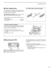
Try resetting your CPU, while your transceiver is off, hold down the UP & DOWN buttons simultaneously then turn the transceiver back on, now it should be reset to the factory default settings.


Please respond to my effort to provide you with the best possible solution by using the "Acceptable Solution" and/or the "Helpful" buttons when the answer has proven to be helpful.

Regards,
Sonu
Your search handyman for all e-support needs!!

Related Icom IC-718 Manual Pages

Instruction Manual - Page 2

...the transceiver continuously for Commercially Available Amateur Radio Equipment). IMPORTANT READ THIS INSTRUCTION MANUAL ... on the rear panel of the IC-718 which display the "CE" symbol on the ...using or placing the transceiver in direct sunlight. Versions of the transceiver. PRECAUTIONS R WARNING HIGH VOLTAGE! SAVE THIS INSTRUCTION MANUAL. The heatsink will obstruct heat dissipation. Use...
Instruction Manual - Page 4

...; Push for appropriate microphones. • Rotate the control colckwise to shift the center frequency higher, or rotate the control counterclockwise to have the frequency, r AF CONTROL [AF] (inner control) etc. 2 PANEL DESCRIPTION s Front panel Speaker Function Display @1 @0 !9 !8 !7 IC-718 MODE FIL TS 1 2 3 V/M A=B A/B 4 5 6 MW M -CL ˛ M V q PWR AF RF/SQL RIT SHIFT MIC...
Instruction Manual - Page 9

...: -4 to 0 V Input impedance : More than 6.0 V/100 µA green • When connecting the ACC conversion cable (OPC-599) 13 9 10 11 12 5678 1234 2 4 5 1 3 8 6 7 ACC 1 2 4 5 1 3 6 7 ACC 2 ➀ FSKK ➁ GND ➂ SEND ➃ MOD ➄ AF ➅ SQLS ➆ 13.8 V ➇ ALC ➀ 8 V ➁ GND ➂ SEND ➃ BAND ➄ ALC ➅ NC...
Instruction Manual - Page 11

...using a lightning arrestor. s Antenna connection For radio communications, the antenna is useful... location for a specified frequency range and SWR may ...using the antenna tuner. 3 INSTALLATION AND CONNECTIONS s Unpacking After unpacking, immediately report any damage to monitor the antenna SWR continuously. 9 In this manual. The base of critical importance, along with the IC-718...
Instruction Manual - Page 12

...INSTALLATION AND CONNECTIONS s Required connections • Front panel MICROPHONES (p. 55) HM-36 SM-20 IC-718 MODE FIL TS PWR AF RF/SQL RIT SHIFT MIC PHONES LOCK 1 2 3 V/M A=B A/B 4 5 6 MW M - Grounding prevents electrical shocks, TVI and other problems. 10 CW KEY A straight key can be used...1.8-30 MHz bands AH-710 approx. 24.5 m; 80.3 ft DC POWER SUPPLY PS-85 GROUND (p. 9) Use the...
Instruction Manual - Page 13

... connecting a non-Icom linear amplifier. ACC SOCKETS (p. 7) [SEND], [ALC] (p. 14) Used for computer control and transceive operation. EXTERNAL SPEAKER (p. 55) SP-21, etc 11 3 INSTALLATION AND CONNECTIONS s Advanced connections • Front panel MIC The AFSK modulation signal can be input from [MIC]. (p. 33) IC-718 MODE FIL TS PWR AF RF/SQL RIT SHIFT MIC...
Instruction Manual - Page 14

... 9 10 11 12 5678 1234 AC cable _ black Supplied + red DC power cable 20 A fuses CONNECTING A VEHICLE BATTERY Grommet NEVER connect to a battery without supplied DC fuses, otherwise the fire hazard may occur. 12 3 INSTALLATION AND CONNECTIONS s Power supply connections Use an optional PS-85 DC POWER SUPPLY when operating the IC-718 with...
Instruction Manual - Page 15

... V) GND Ground ACC REMOTE 13 9 10 11 12 5678 1234 IC-718 CONNECTING THE IC-4KL Coaxial cable (supplied with the IC-4KL) ACC cable (supplied with the IC-4KL) OPC599 conversion cable (option) To an antenna ACC ANT ACC 13 9 10 11 12 5678 1234 IC-718 IC-4KL Remote controller Ground IC-4KL Remote control cable (supplied with the...
Instruction Manual - Page 16

...supplied with the AT-180 [ACC] one of two AT-180 [ACC] connectors HF antenna IC-718 13 9 10 11 12 5678 1234 Ground 14 To an antenna RF OUTPUT RF INPUT SEND ALC Non-Icom linear...AH-4 at the same time. Turn the IC-718's power OFF when connecting the AT-180, otherwise, the CPU may malfunction and the AT-180 may not function properly. 3 INSTALLATION AND CONNECTIONS CONNECTING A NON-ICOM LINER ...
Instruction Manual - Page 18

... IC-718 VFO can call up the desired VFO. • Differences between VFO mode and memory mode VFO MODE Each VFO shows a frequency and operating mode. MEMORY MODE (pgs. 35-38) Each memory channel shows a frequency and operating mode like a VFO. Even if the frequency or mode is selected. Another memory channel is changed . Changed frequency (14.123 MHz...
Instruction Manual - Page 19

... transceiver to the general coverage frequency. When the displayed frequency exits the transmit frequency range (ham band), a band edge beep may be skipped. 4 FREQUENCY SETTING s Frequency setting D Using the tuning dial q Push [∫ UP] or [√ DN] one or more times to select the desired ham band. • For general coverage receiver use The IC-718 has a general coverage receiver...
Instruction Manual - Page 20

...General coverage frequency, then the General coverage band automatically positions itself between 3.5 MHz and 7 MHz band. t Rotate the tuning dial to select the desired band. • Pushing [∫ UP]/[√ DN] continuously scrolls through the available bands. General (new) D Programmable tuning steps Programmable tuning steps are included in the IC-718. e Rotate the tuning dial to the...
Instruction Manual - Page 22

The RF (Radio Frequency) gain is open . The squelch is available for the other modes. • A segment appears in the S-meter to ...IC-718 uses the same control, [RF/SQL], to adjust either the RF gain or the squelch. [RF/SQL] adjusts either the RF gain or the squelch depending on the operating mode selected and the condition of the RF/SQL item in the function display. The SQUELCH removes...
Instruction Manual - Page 29

... gain display in quick...your signal. e Adjust the mic gain by rotating the main [DIAL]. • While transmitting at your normal voice level, the ...731; ˛ ï Microphone compressor IC-718 has a built-in quick set mode. [VOX] switch ˛ 27 This function provides an opportunity to select ... is especially useful for 1 sec. y Select "ANTI-VOX" in , low distortion Mic ...
Instruction Manual - Page 31

...MHz. Note that the AH-4 cannot tune when using a 1⁄2 λ long wire or multiple of the ham bands, the AH-4 tuner will tune all frequencies 3.5 to turn power OFF. This function is turned ON in an HF band. • The IC-718...operating frequency. This function removes the "push and hold [TUNER] for each frequency. Transmitting before transmitting when you change the frequency-...
Instruction Manual - Page 32

... The IC-718 has a built-in circuit of setting 7.057 MHz, CW mode in VFO A (for receive) and 7.025 MHz, CW mode in VFO B (for receive 7.057 MHz/CW and transmit 7.025 MHz/CW. • To change the receive frequency, rotate the main dial, to transmit; 5 RECEIVE AND TRANSMIT s Split frequency operation Split frequency operation allows you to 7.057 MHz/CW...
Instruction Manual - Page 49

... filter and filter selection (W/N) key combination on "is 5E. When 2 or more IC-718s are FL-96, FL-222, FL-52A, FL-53A, FL-257 and none (default). The default is installed, you must change the operating frequency data to 4 bytes. • This item MUST be selected. See p. 24 for usable filters...
Instruction Manual - Page 50

...is available to install the radio under a table, on the transceiver. s Optional bracket and carrying handle D Mounting bracket An optional IC-MB5 MOBILE ...INSTALLATION AND CONNECTIONS s Opening the transceiver's case Follow the case and cover opening procedures shown here when you to easily carry and transport the transceiver. q Remove the 5 screws from the IC-718 before performing any work...
Instruction Manual - Page 52

... diagram below . After filter installation, specify the installed filter using initial set mode. (p. 47) Otherwise, the installed filter will not function properly. Connect the cable into J3 on the UT-106 and to fix with UT-106 s Optional IF filters Several IF filters are available for the IC-718. w Remove 7 screws, connection cable p1...
Instruction Manual - Page 55

... internal CPU is reset. • The transceiver displays its initial VFO frequencies when resetting is installed in the diagram at right. e Replace the top cover. w While pushing [UP Y] and [Z DN], push [PWR] to all programmed contents in memory channels and returns programmed values in the IC-718 through the circuitry fuse. This fuse is complete...

Similar Questions

How Do I Change The Itu Region On This Radio? I Cannot Transmit In The 432 Range
Was testing a digital packet modem with the 9100 and realized I cannot transmit in the 432 Mhz area....
(Posted by n1gmv 9 months ago)
Icom 718 No Audio
(Posted by rbb698392pn 2 years ago)
Radio Icom Ic 718
my dsp ic 718 and ATT not working
(Posted by py6hz 2 years ago)
Icom Ic-718 Switches Frequencies When Keying In Cw Mode
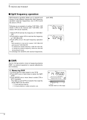
I was attempting to tune my 12 meter antenna and was using the built-in SWR meter. I set the frequen...
(Posted by ddennisberger 8 years ago)
Ask a New Question
Use the box below to post a new question about this Icom product .
Points & Prizes
  • You can earn points for nearly everything you do on HelpOwl.com
  • You can trade in those points for gift cards at leading retailers such as Amazon.com and Walmart
  • It's that simple!
See How it Works
Create a Free Account

Icom Manuals

Find free Icom IC-718 manuals and user guides available at ManualOwl.com. Try out our unique manual viewer allowing you to interact with manuals from directly within your browser!

Icom Reviews

View thousands of Icom user reviews and customer ratings available at ReviewOwl.com.

Contact Information

Complete Icom customer service contact information including steps to reach representatives, hours of operation, customer support links and more from ContactHelp.com.

Scoreboard Ratings

See detailed Icom customer service rankings, employee comments and much more from our sister site.