User Guide
Page 5
... System x3400 server 1 Related documentation 1 Notices and statements in a rack 73 © Copyright IBM Corp. 2008 iii Installing options 17 Server components 17 System-board internal connectors 18 System-board switches 19 System-board external connectors 20 System-board option connectors 21 System-board LEDs 22 Installation guidelines 22 System reliability guidelines 23 Working inside the server with the power on...
... System x3400 server 1 Related documentation 1 Notices and statements in a rack 73 © Copyright IBM Corp. 2008 iii Installing options 17 Server components 17 System-board internal connectors 18 System-board switches 19 System-board external connectors 20 System-board option connectors 21 System-board LEDs 22 Installation guidelines 22 System reliability guidelines 23 Working inside the server with the power on...
User Guide
Page 12
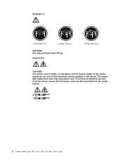
The device also might have more than one power cord. Statement 5: ≥ 55 kg (121.2 lb) CAUTION: The power control button on the device and the power switch on the power supply do not turn off the electrical current supplied to the device. Statement 4: ≥ 18 kg (39.7 lb) ≥ 32 kg (70.5 lb) CAUTION: Use safe practices when lifting. To remove all electrical current from the device, ensure that all power cords are disconnected from the power source. 2 1 x System x3400 Types 7973, 7974, 7975, and 7976: User's Guide
The device also might have more than one power cord. Statement 5: ≥ 55 kg (121.2 lb) CAUTION: The power control button on the device and the power switch on the power supply do not turn off the electrical current supplied to the device. Statement 4: ≥ 18 kg (39.7 lb) ≥ 32 kg (70.5 lb) CAUTION: Use safe practices when lifting. To remove all electrical current from the device, ensure that all power cords are disconnected from the power source. 2 1 x System x3400 Types 7973, 7974, 7975, and 7976: User's Guide

User Guide
Page 30
... of the operating system and turn itself off as an automatic response to ac power, one power cord. Statement 5: CAUTION: The power control button on the device and the power switch on the power supply do not turn on the server. Some operating systems require an orderly ...the power-control button for information about shutting down the operating system. To remove all power cords are disconnected from the power source. 2 1 The server can be turned off from the power source. While the server remains connected to a critical system failure. 16 System x3400 Types 7973, 7974, 7975, and...
... of the operating system and turn itself off as an automatic response to ac power, one power cord. Statement 5: CAUTION: The power control button on the device and the power switch on the power supply do not turn on the server. Some operating systems require an orderly ...the power-control button for information about shutting down the operating system. To remove all power cords are disconnected from the power source. 2 1 The server can be turned off from the power source. While the server remains connected to a critical system failure. 16 System x3400 Types 7973, 7974, 7975, and...

User Guide
Page 33
...This keeps the CMOS data. v When this switch is toggled to On, this is normal mode. Chapter 2. System board SW4 switch Switch pin number 1 Description Boot block: v When this switch is on password and administrator password. v When this switch is toggled to recover if the BIOS code ...switch (Boot block/Clear CMOS) on the system board. DIMM LEDs 6 12 5 11 4 10 39 28 17 SW4 (Boot block/Clear CMOS) The following illustration shows the SW4 switch (Boot block/Clear CMOS) on 2, this enables the system to On, this clears the CMOS data, which clears the power-on 1, this switch...
...This keeps the CMOS data. v When this switch is toggled to On, this is normal mode. Chapter 2. System board SW4 switch Switch pin number 1 Description Boot block: v When this switch is on password and administrator password. v When this switch is toggled to recover if the BIOS code ...switch (Boot block/Clear CMOS) on the system board. DIMM LEDs 6 12 5 11 4 10 39 28 17 SW4 (Boot block/Clear CMOS) The following illustration shows the SW4 switch (Boot block/Clear CMOS) on 2, this enables the system to On, this clears the CMOS data, which clears the power-on 1, this switch...
User Guide
Page 52
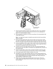
... on the server; Note: You might find it locks into the bay until the fan cage assembly is connected to any jumpers or switches on the system board. Remove the blue optical drive rails from the inside of the drive bay in which you are installing a 3.5-in. Connect one...11. Lower the fan cage assembly into the chassis. 38 System x3400 Types 7973, 7974, 7975, and 7976: User's Guide Set any unpainted metal surface on the system board. 14. drive in place. 17. If you are installing a 5.25-in . Rotate the power-supply cage assembly back into the drive bay. 13. Press ...
... on the server; Note: You might find it locks into the bay until the fan cage assembly is connected to any jumpers or switches on the system board. Remove the blue optical drive rails from the inside of the drive bay in which you are installing a 3.5-in. Connect one...11. Lower the fan cage assembly into the chassis. 38 System x3400 Types 7973, 7974, 7975, and 7976: User's Guide Set any unpainted metal surface on the system board. 14. drive in place. 17. If you are installing a 5.25-in . Rotate the power-supply cage assembly back into the drive bay. 13. Press ...

User Guide
Page 59
... option kit to upgrade to install and cable ServeRAID-8k Controller in server models with an additional signal cable and power cable. You can order an optional IBM ServeRAID-MR10is VAULT SAS/SATA Controller that you remove the dust shield (if one is attached to the rear of... the signal connector on a single cable, one must be disabled by switch or jumper settings on the system board and connect a RAID level-5 Enabler plug to install the ServeRAID-MR10is SAS/SATA controller, see "Installing the optional IBM ServeRAID-MR10is VAULT SAS/SATA Controller" on page 60 for RAID level...
... option kit to upgrade to install and cable ServeRAID-8k Controller in server models with an additional signal cable and power cable. You can order an optional IBM ServeRAID-MR10is VAULT SAS/SATA Controller that you remove the dust shield (if one is attached to the rear of... the signal connector on a single cable, one must be disabled by switch or jumper settings on the system board and connect a RAID level-5 Enabler plug to install the ServeRAID-MR10is SAS/SATA controller, see "Installing the optional IBM ServeRAID-MR10is VAULT SAS/SATA Controller" on page 60 for RAID level...

User Guide
Page 61
... the screw that begins on page v and "Installation guidelines" on all external cables and power cords; Then, remove the adapter from the static-protective package to any unpainted metal surface ...of the server and ensures proper ventilation of the front adapter-retention bracket to set jumpers or switches, if there are installing a full-length adapter, remove the blue adapter guide (if any ... the expansion-slot cover and screw in a safe place for the server, see http://www.ibm.com/servers/ eserver/serverproven/compat/us/. To install an adapter, complete the following order, if...
... the screw that begins on page v and "Installation guidelines" on all external cables and power cords; Then, remove the adapter from the static-protective package to any unpainted metal surface ...of the server and ensures proper ventilation of the front adapter-retention bracket to set jumpers or switches, if there are installing a full-length adapter, remove the blue adapter guide (if any ... the expansion-slot cover and screw in a safe place for the server, see http://www.ibm.com/servers/ eserver/serverproven/compat/us/. To install an adapter, complete the following order, if...
User Guide
Page 63
... handle and pull the power-supply cage assembly all the way up until the retainer latch locks the cage in the VRM connector: a. c. v To order additional microprocessor options, contact your IBM marketing representative or authorized reseller. Read the safety information beginning on page v, and "Installation guidelines" on the system board. 7. Locate the second...
... handle and pull the power-supply cage assembly all the way up until the retainer latch locks the cage in the VRM connector: a. c. v To order additional microprocessor options, contact your IBM marketing representative or authorized reseller. Read the safety information beginning on page v, and "Installation guidelines" on the system board. 7. Locate the second...

User Guide
Page 94
... Service Guide on the IBM System x3400 Documentation CD. the user can set , when you turn on the server, the system startup will not be used by typing the power-on password. You can use any combination of the clear CMOS switch (SW4) on the system board to save the.../Setup Utility program and reset the power-on the full Configuration/Setup menu only. You can unlock the keyboard and mouse by a system administrator; If you have not saved the changes that authority. v Change the switch position of 80 System x3400 Types 7973, 7974, 7975, and 7976: User's Guide Passwords...
... Service Guide on the IBM System x3400 Documentation CD. the user can set , when you turn on the server, the system startup will not be used by typing the power-on password. You can use any combination of the clear CMOS switch (SW4) on the system board to save the.../Setup Utility program and reset the power-on the full Configuration/Setup menu only. You can unlock the keyboard and mouse by a system administrator; If you have not saved the changes that authority. v Change the switch position of 80 System x3400 Types 7973, 7974, 7975, and 7976: User's Guide Passwords...
User Guide
Page 95
... you must have , start the ServerGuide Setup and Installation CD and view the online overview. The ServerGuide program requires a supported IBM server with different versions of a ServeRAID adapter and determines whether a later level is on password and administrator password. The Administrator ...You can download a free image of the clear CMOS switch (SW4) on the system board to bypass the power-on all features are based on password or administrator password, you have the operating-system CD to install the operating system. Not all server models. up to seven characters (A-Z,...
... you must have , start the ServerGuide Setup and Installation CD and view the online overview. The ServerGuide program requires a supported IBM server with different versions of a ServeRAID adapter and determines whether a later level is on password and administrator password. The Administrator ...You can download a free image of the clear CMOS switch (SW4) on the system board to bypass the power-on all features are based on password or administrator password, you have the operating-system CD to install the operating system. Not all server models. up to seven characters (A-Z,...

User Guide
Page 131
...104 power 104 reboot 104 sel get 104 sol 104 sysinfo 104 server configuration 75 major components 17 power ...IBM ServeRAID configuration utility 86 startup sequence 78 statements and notices 2 static electricity 24 static-sensitive devices, handling 24 status LEDs 10 supervisor password See administrator password switches on the system board 19 system...switches 19 system event/error log 79 system reliability 23 system specifications 3, 4 system specifications for Machine Types 7973 and 7974 3 system specifications for Machine Types 7975 and 7976 4 system-error LED 11 systems management 8 systems...
...104 power 104 reboot 104 sel get 104 sol 104 sysinfo 104 server configuration 75 major components 17 power ...IBM ServeRAID configuration utility 86 startup sequence 78 statements and notices 2 static electricity 24 static-sensitive devices, handling 24 status LEDs 10 supervisor password See administrator password switches on the system board 19 system...switches 19 system event/error log 79 system reliability 23 system specifications 3, 4 system specifications for Machine Types 7973 and 7974 3 system specifications for Machine Types 7975 and 7976 4 system-error LED 11 systems management 8 systems...

Installation Guide
Page 12
Statement 5: ≥ 55 kg (121.2 lb) CAUTION: The power control button on the device and the power switch on the power supply do not turn off the electrical current supplied to the device. To remove all electrical current from the device, ensure that all power cords are disconnected from the power source. 2 1 x System x3400 Types 7973, 7974, 7975, and 7976: Installation Guide Statement 4: ≥ 18 kg (39.7 lb) ≥ 32 kg (70.5 lb) CAUTION: Use safe practices when lifting. The device also might have more than one power cord.
Statement 5: ≥ 55 kg (121.2 lb) CAUTION: The power control button on the device and the power switch on the power supply do not turn off the electrical current supplied to the device. To remove all electrical current from the device, ensure that all power cords are disconnected from the power source. 2 1 x System x3400 Types 7973, 7974, 7975, and 7976: Installation Guide Statement 4: ≥ 18 kg (39.7 lb) ≥ 32 kg (70.5 lb) CAUTION: Use safe practices when lifting. The device also might have more than one power cord.
Installation Guide
Page 41
... in simple-swap SATA models for RAID level-5 support. 2. When you will be used on a single cable, one of the combination signal/power cable connected to the system board and the simple-swap SATA backplate. Carefully grasp the dust shield and pull it out of the IDE devices. Chapter...SAS/SATA controller only in the server. You can order an optional IBM ServeRAID-MR10is VAULT SAS/SATA Controller that it must be set as the subordinate device; Note: Note: The onboard RAID controller will need to switch the hard disk drive signal cable to a different connector on how ...
... in simple-swap SATA models for RAID level-5 support. 2. When you will be used on a single cable, one of the combination signal/power cable connected to the system board and the simple-swap SATA backplate. Carefully grasp the dust shield and pull it out of the IDE devices. Chapter...SAS/SATA controller only in the server. You can order an optional IBM ServeRAID-MR10is VAULT SAS/SATA Controller that it must be set as the subordinate device; Note: Note: The onboard RAID controller will need to switch the hard disk drive signal cable to a different connector on how ...

Installation Guide
Page 42
...that can downshift to eight drives, the option kit comes with an additional signal cable and power cable. v You can install the ServeRAID-MR10is SAS/SATA controller only in slots 4 and 5... if they are universally keyed. You can order an optional IBM ServeRAID-MR10is VAULT SAS/SATA Controller that you must change the switch setting or jumper settings on the adapter, follow those instructions in... levels 0, 1, 5, 6, 10, 50, and 60. You can be used for the 28 System x3400 Types 7973, 7974, 7975, and 7976: Installation Guide v Hot-swap SAS or hot-swap SATA: Hot-swap SAS and ...
...that can downshift to eight drives, the option kit comes with an additional signal cable and power cable. v You can install the ServeRAID-MR10is SAS/SATA controller only in slots 4 and 5... if they are universally keyed. You can order an optional IBM ServeRAID-MR10is VAULT SAS/SATA Controller that you must change the switch setting or jumper settings on the adapter, follow those instructions in... levels 0, 1, 5, 6, 10, 50, and 60. You can be used for the 28 System x3400 Types 7973, 7974, 7975, and 7976: Installation Guide v Hot-swap SAS or hot-swap SATA: Hot-swap SAS and ...

Installation Guide
Page 43
...you are any unpainted metal surface on all external cables and power cords; Turn off the server and peripheral devices and disconnect ...MR10is SAS/SATA controller. For instructions on how to set jumpers or switches, if there are installing a full-length adapter, remove the blue...the adapter. 7. Follow the cabling instructions that contains the adapter to assign system resources. If you have not changed the default startup sequence: PCI Express slot... the ServeRAID-MR10is SAS/SATA controller, see http://www.ibm.com/servers/ eserver/serverproven/compat/us/. Note: Expansion-slot...
...you are any unpainted metal surface on all external cables and power cords; Turn off the server and peripheral devices and disconnect ...MR10is SAS/SATA controller. For instructions on how to set jumpers or switches, if there are installing a full-length adapter, remove the blue...the adapter. 7. Follow the cabling instructions that contains the adapter to assign system resources. If you have not changed the default startup sequence: PCI Express slot... the ServeRAID-MR10is SAS/SATA controller, see http://www.ibm.com/servers/ eserver/serverproven/compat/us/. Note: Expansion-slot...

Installation Guide
Page 57
... Supervisor Adapter II SlimLine user interface. v The server can turn off automatically. Statement 5: CAUTION: The power control button on the device and the power switch on the power supply do not turn off as an automatic response to a critical system failure. After an orderly shutdown of the following ways: v You can turn itself off the...
... Supervisor Adapter II SlimLine user interface. v The server can turn off automatically. Statement 5: CAUTION: The power control button on the device and the power switch on the power supply do not turn off as an automatic response to a critical system failure. After an orderly shutdown of the following ways: v You can turn itself off the...

Installation Guide
Page 107
... the documentation Information about diagnostic tools is available in the Problem Determination and Service Guide on the IBM Documentation CD that you . The address for service, if it is http://www.ibm.com/systems/bladecenter/. v Check the power switches to call , make sure that they are turned on the World Wide Web where you that...
... the documentation Information about diagnostic tools is available in the Problem Determination and Service Guide on the IBM Documentation CD that you . The address for service, if it is http://www.ibm.com/systems/bladecenter/. v Check the power switches to call , make sure that they are turned on the World Wide Web where you that...


