User Guide
Page 12
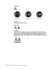
Statement 4: ≥ 18 kg (39.7 lb) ≥ 32 kg (70.5 lb) CAUTION: Use safe practices when lifting. The device also might have more than one power cord. Statement 5: ≥ 55 kg (121.2 lb) CAUTION: The power control button on the device and the power switch on the power supply do not turn off the electrical current supplied to the device. To remove all electrical current from the device, ensure that all power cords are disconnected from the power source. 2 1 x System x3400 Types 7973, 7974, 7975, and 7976: User's Guide
Statement 4: ≥ 18 kg (39.7 lb) ≥ 32 kg (70.5 lb) CAUTION: Use safe practices when lifting. The device also might have more than one power cord. Statement 5: ≥ 55 kg (121.2 lb) CAUTION: The power control button on the device and the power switch on the power supply do not turn off the electrical current supplied to the device. To remove all electrical current from the device, ensure that all power cords are disconnected from the power source. 2 1 x System x3400 Types 7973, 7974, 7975, and 7976: User's Guide
User Guide
Page 24
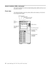
Server controls, LEDs, and power This section describes the controls and light-emitting diodes (LEDs) and how to turn the server on the front of the hot-swap server models. System power LED Power-control button Hard disk drive activity LED System error LED Front information panel CD... or DVD drive activity LED (green) USB connectors CD or DVD-eject button Hot-swap hard disk drive status LED (amber) Hot-swap hard disk drive activity LED (green) 10 System x3400 Types 7973, 7974, 7975...
Server controls, LEDs, and power This section describes the controls and light-emitting diodes (LEDs) and how to turn the server on the front of the hot-swap server models. System power LED Power-control button Hard disk drive activity LED System error LED Front information panel CD... or DVD drive activity LED (green) USB connectors CD or DVD-eject button Hot-swap hard disk drive status LED (amber) Hot-swap hard disk drive activity LED (green) 10 System x3400 Types 7973, 7974, 7975...
User Guide
Page 25
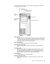
When this LED is off, it indicates that ac power is in the Problem Determination and Service Guide on the IBM System x3400 Documentation CD. Hard disk drive activity LED When this amber LED is in use. System-error LED When this LED is flashing rapidly, it indicates that a ...a system error has occurred. The System x3400 server 11 When this LED is lit, it indicates that the server is turned off manually. CD-eject or DVD-eject button Press this button to ac power. Chapter 1. An LED on the front of the simple-swap server models. System power LED Power-control button Hard ...
When this LED is off, it indicates that ac power is in the Problem Determination and Service Guide on the IBM System x3400 Documentation CD. Hard disk drive activity LED When this amber LED is in use. System-error LED When this LED is flashing rapidly, it indicates that a ...a system error has occurred. The System x3400 server 11 When this LED is lit, it indicates that the server is turned off manually. CD-eject or DVD-eject button Press this button to ac power. Chapter 1. An LED on the front of the simple-swap server models. System power LED Power-control button Hard ...
User Guide
Page 27
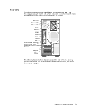
.../100 (for Remote Supervisor Adapter II SlimLine) NMI button Serial 2 (COM 2) The following illustration shows the LEDs and connectors on the rear of the non-hot-swap power supply models. Chapter 1. For more information about these connectors, see "Server components" on page 17. The System x3400 server 13 Rear view The following illustration shows...
.../100 (for Remote Supervisor Adapter II SlimLine) NMI button Serial 2 (COM 2) The following illustration shows the LEDs and connectors on the rear of the non-hot-swap power supply models. Chapter 1. For more information about these connectors, see "Server components" on page 17. The System x3400 server 13 Rear view The following illustration shows...
User Guide
Page 28
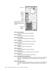
... (RJ45) Ethernet 10/100 (for Remote Supervisor Adapter II SlimLine) NMI button Serial 2 (COM 2) Power-cord connector Connect the power cord to this connector. Ethernet transmit/receive activity LED This LED is an active connection on the Ethernet port. 14 System x3400 Types 7973, 7974, 7975, and 7976: User's Guide Mouse connector Connect a mouse device to...
... (RJ45) Ethernet 10/100 (for Remote Supervisor Adapter II SlimLine) NMI button Serial 2 (COM 2) Power-cord connector Connect the power cord to this connector. Ethernet transmit/receive activity LED This LED is an active connection on the Ethernet port. 14 System x3400 Types 7973, 7974, 7975, and 7976: User's Guide Mouse connector Connect a mouse device to...
User Guide
Page 29
... server will restart automatically when power is restored. Note: When 4 GB or more fans (some memory is reserved for various system resources and is unavailable to turn on the server. The server can turn on the server. The System x3400 server 15 v If an ...or logical) is installed, some models) might start the operating system by pressing the power-control button. v If your operating system supports the systems-management software for an optional Remote Supervisor Adapter II SlimLine, the systems-management software can respond to remote requests from the Remote Supervisor ...
... server will restart automatically when power is restored. Note: When 4 GB or more fans (some memory is reserved for various system resources and is unavailable to turn on the server. The server can turn on the server. The System x3400 server 15 v If an ...or logical) is installed, some models) might start the operating system by pressing the power-control button. v If your operating system supports the systems-management software for an optional Remote Supervisor Adapter II SlimLine, the systems-management software can respond to remote requests from the Remote Supervisor ...

User Guide
Page 30
... connected to ac power, the server can press the power-control button to start an orderly shutdown of the operating system and turn off the server, if your operating-system documentation for more than one or more fans (some models) might have more than 4 seconds to a critical system failure. 16 System x3400 Types 7973, 7974, 7975, and 7976: User...
... connected to ac power, the server can press the power-control button to start an orderly shutdown of the operating system and turn off the server, if your operating-system documentation for more than one or more fans (some models) might have more than 4 seconds to a critical system failure. 16 System x3400 Types 7973, 7974, 7975, and 7976: User...

User Guide
Page 38
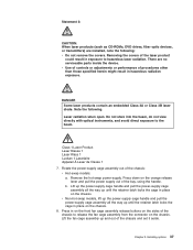
... electricity can damage the server and other grounding system when working inside the server with the power on the outside of a grounding system is recommended. Heating reduces indoor humidity and increases static electricity. 24 System x3400 Types 7973, 7974, 7975, and 7976: User's Guide do not wear..., pins, or exposed circuitry. v Take additional care when handling devices during cold weather. v Remove the device from your forearms. Button long-sleeved shirts before working inside the server; The server (some models) supports hot-swap devices and is designed to operate safely ...
... electricity can damage the server and other grounding system when working inside the server with the power on the outside of a grounding system is recommended. Heating reduces indoor humidity and increases static electricity. 24 System x3400 Types 7973, 7974, 7975, and 7976: User's Guide do not wear..., pins, or exposed circuitry. v Take additional care when handling devices during cold weather. v Remove the device from your forearms. Button long-sleeved shirts before working inside the server; The server (some models) supports hot-swap devices and is designed to operate safely ...
User Guide
Page 41
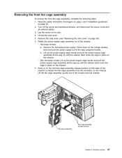
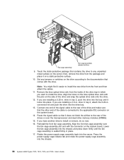
...cage assembly up until the retainer latch locks the cage in on the front fan cage assembly release buttons on the chassis. Lift up the power-supply cage handle and pull the power-supply cage assembly all the way up until the retainer latch locks the cage in place on ...its side. 4. Fan cage assembly Fan cage assembly release buttons Chapter 2. Removing the front fan cage assembly To remove the front fan cage assembly, complete the following steps: 1. v Non-hot-swap models, lift up the power-supply cage handle and pull the power-supply cage assembly all external cables. 3.
...cage assembly up until the retainer latch locks the cage in on the front fan cage assembly release buttons on the chassis. Lift up the power-supply cage handle and pull the power-supply cage assembly all the way up until the retainer latch locks the cage in place on ...its side. 4. Fan cage assembly Fan cage assembly release buttons Chapter 2. Removing the front fan cage assembly To remove the front fan cage assembly, complete the following steps: 1. v Non-hot-swap models, lift up the power-supply cage handle and pull the power-supply cage assembly all external cables. 3.
User Guide
Page 51
...optic devices, or transmitters) are no serviceable parts inside the device. Laser radiation when open. Remove the hot-swap power-supply. Press in on the front fan cage assembly release buttons on the sides of the chassis to release the fan cage assembly from the connector on the orange release lever... and pull the power supply out of the laser product could result in hazardous radiation exposure. There are installed, note...
...optic devices, or transmitters) are no serviceable parts inside the device. Laser radiation when open. Remove the hot-swap power-supply. Press in on the front fan cage assembly release buttons on the sides of the chassis to release the fan cage assembly from the connector on the orange release lever... and pull the power supply out of the laser product could result in hazardous radiation exposure. There are installed, note...
User Guide
Page 52
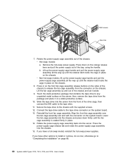
... the drive and snap the optical drive rails onto the drive. 12. Rotate the power-supply cage assembly back into the chassis and press down firmly until it does not block...seated firmly in bay 2, push the drive into place. Fan cage assembly Fan cage assembly release buttons 9. then, remove the drive from the front and then attach the cables. 11. Align the... Reinstall the front fan cage assembly. conversion kit and push the drive into the chassis. 38 System x3400 Types 7973, 7974, 7975, and 7976: User's Guide If you are installing a 5.25-in which you have another drive...
... the drive and snap the optical drive rails onto the drive. 12. Rotate the power-supply cage assembly back into the chassis and press down firmly until it does not block...seated firmly in bay 2, push the drive into place. Fan cage assembly Fan cage assembly release buttons 9. then, remove the drive from the front and then attach the cables. 11. Align the... Reinstall the front fan cage assembly. conversion kit and push the drive into the chassis. 38 System x3400 Types 7973, 7974, 7975, and 7976: User's Guide If you are installing a 5.25-in which you have another drive...
User Guide
Page 54
...pull the power-supply cage assembly all the way up until the retainer latch locks the cage in on the front fan cage assembly release buttons on the sides of the drive cage, then connect the IDE cable to the tape drive connector on page 68. 40 System x3400 Types 7973, 7974, 7975, and ...7976: User's Guide v Non-hot-swap models, lift up the power-supply cage handle and pull the power-supply cage assembly all...
...pull the power-supply cage assembly all the way up until the retainer latch locks the cage in on the front fan cage assembly release buttons on the sides of the drive cage, then connect the IDE cable to the tape drive connector on page 68. 40 System x3400 Types 7973, 7974, 7975, and ...7976: User's Guide v Non-hot-swap models, lift up the power-supply cage handle and pull the power-supply cage assembly all...

User Guide
Page 85
... 3 (RJ45) Ethernet 10/100/1000 (RJ45) Ethernet 10/100 (for Remote Supervisor Adapter II SlimLine) NMI button Serial 2 (COM 2) The following illustration shows the input/output (I /O) connectors on the rear of the non-hot-swap power supply models. Connecting the cables Attention: To prevent damage to equipment, connect the... last. For example, match a blue cable end with a blue panel connector, a red cable end with optional redundant power. The following illustration shows the input/output (I /O) connectors on . Installing options 71 If the server cables and connector panel have color-...
... 3 (RJ45) Ethernet 10/100/1000 (RJ45) Ethernet 10/100 (for Remote Supervisor Adapter II SlimLine) NMI button Serial 2 (COM 2) The following illustration shows the input/output (I /O) connectors on the rear of the non-hot-swap power supply models. Connecting the cables Attention: To prevent damage to equipment, connect the... last. For example, match a blue cable end with a blue panel connector, a red cable end with optional redundant power. The following illustration shows the input/output (I /O) connectors on . Installing options 71 If the server cables and connector panel have color-...
User Guide
Page 86
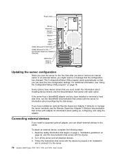
...device to prepare it for installation and to connect it to the server. 72 System x3400 Types 7973, 7974, 7975, and 7976: User's Guide Turn off the server and all attached devices. ... Connecting external devices If you install a supported optional adapter, you can save the new configuration settings. Power cords Mouse Keyboard Serial 1 (COM 1) Parallel Video USB 4 USB 3 (RJ45) Ethernet 10/100.../1000 (RJ45) Ethernet 10/100 (for Remote Supervisor Adapter II SlimLine) NMI button Serial 2 (COM 2) Updating the server configuration When you start the server for the first time ...
...device to prepare it for installation and to connect it to the server. 72 System x3400 Types 7973, 7974, 7975, and 7976: User's Guide Turn off the server and all attached devices. ... Connecting external devices If you install a supported optional adapter, you can save the new configuration settings. Power cords Mouse Keyboard Serial 1 (COM 1) Parallel Video USB 4 USB 3 (RJ45) Ethernet 10/100.../1000 (RJ45) Ethernet 10/100 (for Remote Supervisor Adapter II SlimLine) NMI button Serial 2 (COM 2) Updating the server configuration When you start the server for the first time ...
User Guide
Page 127
... Boot Menu program 75, 83 boot sequence 78 Broadcom Gigabit Ethernet Utility enabling 83 general information 75 C cables internal drives 44 power 44 © Copyright IBM Corp. 2008 cables (continued) rear connectors 71 signal 44 cabling hot-swap SAS drives 45 hot-swap SATA drives 45 Simple-...the ServeRAID-MR10is adapter 60 cache control 78 caution statements 2 CD drive activity LED 12 eject button 11 specifications 3, 4 Class A electronic emission notice 109 command-line interface commands identify 103 power 103 sel 103 sysinfo 103 for remote management 103 components in the server 17 major 17 ...
... Boot Menu program 75, 83 boot sequence 78 Broadcom Gigabit Ethernet Utility enabling 83 general information 75 C cables internal drives 44 power 44 © Copyright IBM Corp. 2008 cables (continued) rear connectors 71 signal 44 cabling hot-swap SAS drives 45 hot-swap SATA drives 45 Simple-...the ServeRAID-MR10is adapter 60 cache control 78 caution statements 2 CD drive activity LED 12 eject button 11 specifications 3, 4 Class A electronic emission notice 109 command-line interface commands identify 103 power 103 sel 103 sysinfo 103 for remote management 103 components in the server 17 major 17 ...
User Guide
Page 128
...-swap and hot-plug devices adapters 56 114 System x3400 Types 7973, 7974, 7975, and 7976: User's Guide connector (continued) mouse 14 parallel 14 power cord 14 serial 1 14 serial 2 14 Universal Serial Bus (USB) 11, 14 video 14 connectors system board 21 controller BMC 6 enabling 77 Ethernet,... SATA cabling 45 dual inline memory module (DIMM) connectors 31 installing 31 retaining clips 32 DVD drive activity LED 12 eject button 11 E eject button CD 11 eject button (continued) DVD 11 electrical input 3, 4, 5 electromagnetic compatibility (EMC) shield 36 electronic emission Class A notice 109 EMC ...
...-swap and hot-plug devices adapters 56 114 System x3400 Types 7973, 7974, 7975, and 7976: User's Guide connector (continued) mouse 14 parallel 14 power cord 14 serial 1 14 serial 2 14 Universal Serial Bus (USB) 11, 14 video 14 connectors system board 21 controller BMC 6 enabling 77 Ethernet,... SATA cabling 45 dual inline memory module (DIMM) connectors 31 installing 31 retaining clips 32 DVD drive activity LED 12 eject button 11 E eject button CD 11 eject button (continued) DVD 11 electrical input 3, 4, 5 electromagnetic compatibility (EMC) shield 36 electronic emission Class A notice 109 EMC ...
User Guide
Page 130
... Bus (USB) 11, 14 video 14 power control-button 11 power supply hot-swap installing 53 installing 54 replacing 52 safety 52 specifications 3, 5 power-cord connector 14 power-cord safety xii power-on LED 11 power-on password 80 power-on 24 SAS/SATA configuring RAID arrays 85 116 System x3400 Types 7973, 7974, 7975, and 7976: User's Guide network operating...
... Bus (USB) 11, 14 video 14 power control-button 11 power supply hot-swap installing 53 installing 54 replacing 52 safety 52 specifications 3, 5 power-cord connector 14 power-cord safety xii power-on LED 11 power-on password 80 power-on 24 SAS/SATA configuring RAID arrays 85 116 System x3400 Types 7973, 7974, 7975, and 7976: User's Guide network operating...

Installation Guide
Page 12
Statement 4: ≥ 18 kg (39.7 lb) ≥ 32 kg (70.5 lb) CAUTION: Use safe practices when lifting. The device also might have more than one power cord. To remove all electrical current from the device, ensure that all power cords are disconnected from the power source. 2 1 x System x3400 Types 7973, 7974, 7975, and 7976: Installation Guide Statement 5: ≥ 55 kg (121.2 lb) CAUTION: The power control button on the device and the power switch on the power supply do not turn off the electrical current supplied to the device.
Statement 4: ≥ 18 kg (39.7 lb) ≥ 32 kg (70.5 lb) CAUTION: Use safe practices when lifting. The device also might have more than one power cord. To remove all electrical current from the device, ensure that all power cords are disconnected from the power source. 2 1 x System x3400 Types 7973, 7974, 7975, and 7976: Installation Guide Statement 5: ≥ 55 kg (121.2 lb) CAUTION: The power control button on the device and the power switch on the power supply do not turn off the electrical current supplied to the device.

Installation Guide
Page 25
...scarf to hang inside the server with the power on. v Avoid dropping any metallic objects, such as you are ready to set down the device. Always use of a grounding system is necessary to install them. v Take ... pins, or exposed circuitry. v Remove the device from its frame. Movement can damage the server and other grounding system when working inside the server. v Remove items from your body. v While the device is available. Chapter 2.... movement. v Avoid wearing loose-fitting clothing on your forearms. Button long-sleeved shirts before working inside the server.
...scarf to hang inside the server with the power on. v Avoid dropping any metallic objects, such as you are ready to set down the device. Always use of a grounding system is necessary to install them. v Take ... pins, or exposed circuitry. v Remove the device from its frame. Movement can damage the server and other grounding system when working inside the server. v Remove items from your body. v While the device is available. Chapter 2.... movement. v Avoid wearing loose-fitting clothing on your forearms. Button long-sleeved shirts before working inside the server.

Installation Guide
Page 29
... on page v and "Installation guidelines" on page 12). 4. Rotate the power-supply cage assembly out of the chassis and set it aside. Press down on the chassis. b. Fan cage assembly Fan cage assembly release buttons Chapter 2. Removing the front fan cage assembly To remove the front fan cage... assembly, complete the following steps: 1. Turn off the server and peripheral devices, and disconnect the power cords and all the way up and out of the...
... on page v and "Installation guidelines" on page 12). 4. Rotate the power-supply cage assembly out of the chassis and set it aside. Press down on the chassis. b. Fan cage assembly Fan cage assembly release buttons Chapter 2. Removing the front fan cage assembly To remove the front fan cage... assembly, complete the following steps: 1. Turn off the server and peripheral devices, and disconnect the power cords and all the way up and out of the...


