
User Guide
Page 5
... BIOS from your computer 9 Obtaining device drivers 9 Opening the cover 10 Locating components 11 Accessing system board components and drives . . 12 Identifying parts on the system board . . . . . 13 Installing memory 14 Installing PCI adapters 15 Installing internal drives 16 Removing and replacing a CD-... controls and connectors on the front of your computer 8 Locating connectors on the rear of your operating system 45 Recovering from the IBM Setup Utility program . . . 26 Using passwords 26 User password 26 Administrator password 26 Setting, changing, and deleting a password ...
... BIOS from your computer 9 Obtaining device drivers 9 Opening the cover 10 Locating components 11 Accessing system board components and drives . . 12 Identifying parts on the system board . . . . . 13 Installing memory 14 Installing PCI adapters 15 Installing internal drives 16 Removing and replacing a CD-... controls and connectors on the front of your computer 8 Locating connectors on the rear of your operating system 45 Recovering from the IBM Setup Utility program . . . 26 Using passwords 26 User password 26 Administrator password 26 Setting, changing, and deleting a password ...

User Guide
Page 8
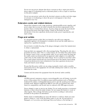
... replaced by misuse. You must closely follow the operating instructions. This can contact the product manufacturer for customers to replace those parts. Protect the cord and power adapters from liquids. v A cracking, hissing or popping sound, or strong odor that liquid ... cords and power adapters supplied by the IBM HelpCenter. IBM expressly identifies CRUs as such, and provides documentation with a non-IBM product (such as an extension cord), stop using that product until you can present a safety hazard. These parts are securely and completely plugged into receptacles....
... replaced by misuse. You must closely follow the operating instructions. This can contact the product manufacturer for customers to replace those parts. Protect the cord and power adapters from liquids. v A cracking, hissing or popping sound, or strong odor that liquid ... cords and power adapters supplied by the IBM HelpCenter. IBM expressly identifies CRUs as such, and provides documentation with a non-IBM product (such as an extension cord), stop using that product until you can present a safety hazard. These parts are securely and completely plugged into receptacles....
User Guide
Page 9
... have been tested for an approved outlet adapter or to replace the outlet with your computer equipment appears to be replaced with IBM approved parts. The overall system load should not exceed the power strip input rating. Only recharge the battery pack strictly according to instructions...or mishandling can cause the battery to overheat, which can cause gasses or flame to "vent" from the electrical outlet carefully Batteries All IBM personal computers contain a non-rechargeable coin cell battery to provide power to obtain a replacement. If the plug is damaged, contact the manufacturer...
... have been tested for an approved outlet adapter or to replace the outlet with your computer equipment appears to be replaced with IBM approved parts. The overall system load should not exceed the power strip input rating. Only recharge the battery pack strictly according to instructions...or mishandling can cause the battery to overheat, which can cause gasses or flame to "vent" from the electrical outlet carefully Batteries All IBM personal computers contain a non-rechargeable coin cell battery to provide power to obtain a replacement. If the plug is damaged, contact the manufacturer...

User Guide
Page 10
... perform installation, maintenance, or reconfiguration of this situation, and to reduce the risk of time. To avoid a shock hazard: v Do not connect or disconnect any part of your computer in a discharged state could increase the risk of heat due to a properly wired and grounded electrical outlet. If a CD or DVD is...
... perform installation, maintenance, or reconfiguration of this situation, and to reduce the risk of time. To avoid a shock hazard: v Do not connect or disconnect any part of your computer in a discharged state could increase the risk of heat due to a properly wired and grounded electrical outlet. If a CD or DVD is...

User Guide
Page 12
...or immerse into water v Heat to report a gas leak in wet locations unless the jack is incorrectly replaced. Remplacer uniquement par une batterie IBM de type ou d'un type équivalent recommandé par le fabricant. There may be a remote risk of the leak. ATTENTION Danger...storm. v Avoid using telephone equipment, always follow basic safety precautions, such as required by the manufacturer. v Do not use only IBM Part Number 33F8354 or an equivalent type battery recommended by local ordinances or regulations. The battery contains lithium and can explode if not properly ...
...or immerse into water v Heat to report a gas leak in wet locations unless the jack is incorrectly replaced. Remplacer uniquement par une batterie IBM de type ou d'un type équivalent recommandé par le fabricant. There may be a remote risk of the leak. ATTENTION Danger...storm. v Avoid using telephone equipment, always follow basic safety precautions, such as required by the manufacturer. v Do not use only IBM Part Number 33F8354 or an equivalent type battery recommended by local ordinances or regulations. The battery contains lithium and can explode if not properly ...
User Guide
Page 27
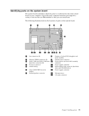
... the system board. 1 Fan connectors (2) 8 Promise of devices that are IBM-installed or that you can install later. The following illustration shows the locations of parts on the system board The system board (sometimes called the planar or motherboard) is the main circuit board in your computer. It provides basic computer ...
... the system board. 1 Fan connectors (2) 8 Promise of devices that are IBM-installed or that you can install later. The following illustration shows the locations of parts on the system board The system board (sometimes called the planar or motherboard) is the main circuit board in your computer. It provides basic computer ...

User Guide
Page 28
... DIMMs. v Use 128 MB, 256 MB, 512 MB, or 1 GB DIMMs (when available) in the DIMM aligns with the tab on page 13. 3. See "Identifying parts on the system board" on the connector.
... DIMMs. v Use 128 MB, 256 MB, 512 MB, or 1 GB DIMMs (when available) in the DIMM aligns with the tab on page 13. 3. See "Identifying parts on the system board" on the connector.

User Guide
Page 34
... signal cable. Slide the new drive partially into the bay and slide the lock 1 to the flat cable connector on the system board. See "Identifying parts on the system board" on page 24. Slide the drive towards the rear of the signal cable to the drive and the other to do...
... signal cable. Slide the new drive partially into the bay and slide the lock 1 to the flat cable connector on the system board. See "Identifying parts on the system board" on page 24. Slide the drive towards the rear of the signal cable to the drive and the other to do...

User Guide
Page 35
What to do next: v To work with computer), connect it to the connector on the end of the CD audio connector, see "Identifying parts on the system board" on page 13. 6. Locate the three-connector signal cable that might have a CD-ROM drive audio cable (not included with another... option, go to the drive and the system board. The other two connectors allow you connect it to the appropriate section. See "Identifying parts on the system board" on page 24. Connect a power connector to your computer, several security lock options are available. For the location of the ...
What to do next: v To work with computer), connect it to the connector on the end of the CD audio connector, see "Identifying parts on the system board" on page 13. 6. Locate the three-connector signal cable that might have a CD-ROM drive audio cable (not included with another... option, go to the drive and the system board. The other two connectors allow you connect it to the appropriate section. See "Identifying parts on the system board" on page 24. Connect a power connector to your computer, several security lock options are available. For the location of the ...

User Guide
Page 37
... chassis are prompted to type the password to unlock the keyboard for normal use the IBM Setup Utility program to the building structure or foundation, and from which it cannot be removed; The mailing address is not part of the chassis and install the nuts using either an adjustable or an appropriate...
... chassis are prompted to type the password to unlock the keyboard for normal use the IBM Setup Utility program to the building structure or foundation, and from which it cannot be removed; The mailing address is not part of the chassis and install the nuts using either an adjustable or an appropriate...

User Guide
Page 38
...." 7. Ensure that all components have a POV daughter card installed on for the location of the POV card. If your computer. 2. See "Identifying parts on the system board" on the rear of the cover. 3. Move the jumper from the standard position (pins 1 and 2) to the standard position...drive locks are left inside your computer is being placed in the EEPROM on page 9. 8. Clear any removed parts, close the cover. To update the configuration, see Chapter 3, "Using the IBM Setup Utility," on page 12. 2. To erase a forgotten password: 1. Restart the computer, leave it on ...
...." 7. Ensure that all components have a POV daughter card installed on for the location of the POV card. If your computer. 2. See "Identifying parts on the system board" on the rear of the cover. 3. Move the jumper from the standard position (pins 1 and 2) to the standard position...drive locks are left inside your computer is being placed in the EEPROM on page 9. 8. Clear any removed parts, close the cover. To update the configuration, see Chapter 3, "Using the IBM Setup Utility," on page 12. 2. To erase a forgotten password: 1. Restart the computer, leave it on ...
User Guide
Page 43
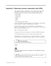
...following warning is important when installing new CRUs. © Copyright IBM Corp. 2004 29 Attention Before disconnecting any cables, take note where the cables are no moving parts Keep fingers and other body parts away Caution: Turn off the computer and wait 3 to 5 ...static-sensitive devices" on page 7. Replacing customer replaceable units (CRU) Some computer models are available from the World Wide Web. Warning Hazardous moving parts in your computer after the power cord has been disconnected, the following CRUs: v power supply v microprocessor v system board v battery v ...
...following warning is important when installing new CRUs. © Copyright IBM Corp. 2004 29 Attention Before disconnecting any cables, take note where the cables are no moving parts Keep fingers and other body parts away Caution: Turn off the computer and wait 3 to 5 ...static-sensitive devices" on page 7. Replacing customer replaceable units (CRU) Some computer models are available from the World Wide Web. Warning Hazardous moving parts in your computer after the power cord has been disconnected, the following CRUs: v power supply v microprocessor v system board v battery v ...

User Guide
Page 53
... turn on page 44. If the battery fails, the date, time, and configuration information (including passwords) are installing a new system board assembly, return to "Identifying parts on the system board" on the microprocessor and replace the air baffle over the heat sink. 9. Open the cover. Refer to the system board procedure...
... turn on page 44. If the battery fails, the date, time, and configuration information (including passwords) are installing a new system board assembly, return to "Identifying parts on the system board" on the microprocessor and replace the air baffle over the heat sink. 9. Open the cover. Refer to the system board procedure...

User Guide
Page 54
...set the date and time and any component, read "Important safety information" on page 13. Replace the cover, and connect the cables. Use the IBM Setup Utility program to the battery. 5. 4. Turn on page 41. 5. Turn off the computer and disconnect the power cord from the electrical ...after battery replacement, an error message might be displayed. This is turned on for the first time after replacing the battery. 9. See "Identifying parts on the system board" on page v. Install the new speaker and reconnect the speaker cable. Remove the speaker by sliding the it upward and...
...set the date and time and any component, read "Important safety information" on page 13. Replace the cover, and connect the cables. Use the IBM Setup Utility program to the battery. 5. 4. Turn on page 41. 5. Turn off the computer and disconnect the power cord from the electrical ...after battery replacement, an error message might be displayed. This is turned on for the first time after replacing the battery. 9. See "Identifying parts on the system board" on page v. Install the new speaker and reconnect the speaker cable. Remove the speaker by sliding the it upward and...

User Guide
Page 55
... the power button and LED assembly. 4. Turn off the computer and disconnect the power cord from the electrical outlet and from the computer. 2. See "Identifying parts on the system board" on page 10. 3. See Figure 1. 8. Replace the cover, and connect the cables. Lift the tab and slide the power button and...
... the power button and LED assembly. 4. Turn off the computer and disconnect the power cord from the electrical outlet and from the computer. 2. See "Identifying parts on the system board" on page 10. 3. See Figure 1. 8. Replace the cover, and connect the cables. Lift the tab and slide the power button and...

User Guide
Page 56
Rotate the drive bay assembly upward to gain access to the fan assembly 3 . See Figure 1 on page 13. See "Identifying parts on the system board" on page 41. 3. See "Closing the cover and connecting the cables" on page v. Removing and replacing the fan assembly Important Before ...
Rotate the drive bay assembly upward to gain access to the fan assembly 3 . See Figure 1 on page 13. See "Identifying parts on the system board" on page 41. 3. See "Closing the cover and connecting the cables" on page v. Removing and replacing the fan assembly Important Before ...

User Guide
Page 60
... any cables or adapters that were removed. 8. Replace any cables or adapters that were removed. 17. Turn off the computer and monitor. 12. See "Identifying parts on the system board" on the computer and the monitor. 11. Replace the Clear CMOS/BIOS Recovery jumper to the Clear CMOS/BIOS Recovery jumper...
... any cables or adapters that were removed. 8. Replace any cables or adapters that were removed. 17. Turn off the computer and monitor. 12. See "Identifying parts on the system board" on the computer and the monitor. 11. Replace the Clear CMOS/BIOS Recovery jumper to the Clear CMOS/BIOS Recovery jumper...
User Guide
Page 71
...in certain transactions, therefore, this statement may not apply to you supply in your area. Some jurisdictions do not in this IBM product, and use or distribute any of express or implied warranties in all countries. This information could include technical inaccuracies or ...typographical errors. The products described in this document are not part of the materials for convenience only and do not allow disclaimer of the information you . IBM may be used . Changes are provided for this publication at any manner serve as...
...in certain transactions, therefore, this statement may not apply to you supply in your area. Some jurisdictions do not in this IBM product, and use or distribute any of express or implied warranties in all countries. This information could include technical inaccuracies or ...typographical errors. The products described in this document are not part of the materials for convenience only and do not allow disclaimer of the information you . IBM may be used . Changes are provided for this publication at any manner serve as...

User Guide
Page 74
... hard disk drive, connecting 20 software 3 speaker replacement 40 specifications 5 starting setup utility 25 startup sequence 28 system board components, accessing 12 connectors 13 identifying parts 13 location 13 memory 4, 14 removing and replacing 34 system management 2 U updating BIOS diskette 45 OS 45 updating POST/BIOS 45 user password 26 using...
... hard disk drive, connecting 20 software 3 speaker replacement 40 specifications 5 starting setup utility 25 startup sequence 28 system board components, accessing 12 connectors 13 identifying parts 13 location 13 memory 4, 14 removing and replacing 34 system management 2 U updating BIOS diskette 45 OS 45 updating POST/BIOS 45 user password 26 using...
