
Installation Guide
Page 5
... 51 Chapter 6. Introduction 1 The IBM Documentation CD 2 Hardware and software requirements 2 Using the Documentation Browser 2 Notices and statements in a single-power-supply server operating at 110 V ac installation 10 System reliability guidelines 10 Working inside the server with the power on the server 41 Turning off the server 42 Chapter 4. Server controls, connectors, LEDs, and power 37...
... 51 Chapter 6. Introduction 1 The IBM Documentation CD 2 Hardware and software requirements 2 Using the Documentation Browser 2 Notices and statements in a single-power-supply server operating at 110 V ac installation 10 System reliability guidelines 10 Working inside the server with the power on the server 41 Turning off the server 42 Chapter 4. Server controls, connectors, LEDs, and power 37...
Installation Guide
Page 8
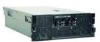
... is used to read all caution and danger statements in the Safety Information document under "Statement 1." vi IBM System x3850 M2 and System x3950 M2 Types 7141 and 7233: Installation Guide For example, if a caution statement is labeled with the server or optional device before you install the device. Läs säkerhetsinformationen innan du installerar den hä...
... is used to read all caution and danger statements in the Safety Information document under "Statement 1." vi IBM System x3850 M2 and System x3950 M2 Types 7141 and 7233: Installation Guide For example, if a caution statement is labeled with the server or optional device before you install the device. Läs säkerhetsinformationen innan du installerar den hä...
Installation Guide
Page 13
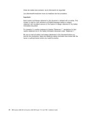
...devices v Solving problems If firmware and documentation updates are available, you can obtain up your IBM® System x3850 M2 and System x3950 M2 Types 7141 and 7233 servers and basic instructions for installing some optional devices. To check for locating firmware and documentation might...you configure the hardware, install device drivers, and install the operating system. More detailed instructions for documentation updates. Product name Machine type Model number Serial number IBM System x3850 M2 or System x3950 M2 server 7141 or 7233 The model number and serial number are made ...
...devices v Solving problems If firmware and documentation updates are available, you can obtain up your IBM® System x3850 M2 and System x3950 M2 Types 7141 and 7233 servers and basic instructions for installing some optional devices. To check for locating firmware and documentation might...you configure the hardware, install device drivers, and install the operating system. More detailed instructions for documentation updates. Product name Machine type Model number Serial number IBM System x3850 M2 or System x3950 M2 server 7141 or 7233 The model number and serial number are made ...
Installation Guide
Page 14
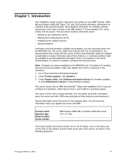
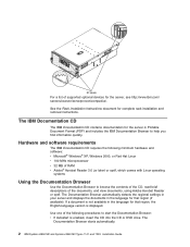
... Acrobat Reader or xpdf. The Documentation Browser starts automatically. 2 IBM System x3850 M2 and System x3950 M2 Types 7141 and 7233: Installation Guide ID labels For a list of supported optional devices for that region (if available). The Documentation Browser automatically detects the regional settings in your server and displays the documents in Portable Document Format (PDF) and...
... Acrobat Reader or xpdf. The Documentation Browser starts automatically. 2 IBM System x3850 M2 and System x3950 M2 Types 7141 and 7233: Installation Guide ID labels For a list of supported optional devices for that region (if available). The Documentation Browser automatically detects the regional settings in your server and displays the documents in Portable Document Format (PDF) and...

Installation Guide
Page 15
... or extremely hazardous procedure step or situation. v Important: These notices provide information or advice that can be in which is on the IBM System x Documentation CD. A caution statement is placed just before the description of the CD or DVD drive, and click OK. - Click...you select a document, a description of the most occurrences. The following command from the /mnt/cdrom directory: sh runlinux.sh Select the server from the Product menu. Chapter 1. When you select the documents. v Attention: These notices indicate potential damage to you avoid inconvenient or...
... or extremely hazardous procedure step or situation. v Important: These notices provide information or advice that can be in which is on the IBM System x Documentation CD. A caution statement is placed just before the description of the CD or DVD drive, and click OK. - Click...you select a document, a description of the most occurrences. The following command from the /mnt/cdrom directory: sh runlinux.sh Select the server from the Product menu. Chapter 1. When you select the documents. v Attention: These notices indicate potential damage to you avoid inconvenient or...
Installation Guide
Page 16
...marked in controlled acoustical environments according to as a unit, or "U." Power consumption and heat output vary depending on the server model, some features might not be available, or some specifications might exceed the average values stated because of 4.45 ... the server. Actual sound-pressure levels in accordance with ISO 9296. Notes: 1. Features and specifications The following information is 4.45 cm (1.75 inches) tall. 2. A 1-U-high device is a summary of the features and specifications of computers will operate. 4 IBM System x3850 M2 and System x3950 M2 Types 7141...
...marked in controlled acoustical environments according to as a unit, or "U." Power consumption and heat output vary depending on the server model, some features might not be available, or some specifications might exceed the average values stated because of 4.45 ... the server. Actual sound-pressure levels in accordance with ISO 9296. Notes: 1. Features and specifications The following information is 4.45 cm (1.75 inches) tall. 2. A 1-U-high device is a summary of the features and specifications of computers will operate. 4 IBM System x3850 M2 and System x3950 M2 Types 7141...
Installation Guide
Page 17
...lb) when fully configured or 31.75 kg (70 lb) minimum Integrated functions: v Baseboard management controller v IBM EXA-4 chip set with RAID capabilities v Support for ServeRAID-MR10k SAS controller v Serial connector v SMP Expansion...half-length) slots: v Five non-hot-swap v Two hot-swap Upgradeable microcode: System BIOS, FPGA, diagnostics, service processor, BMC, and SAS microcode Power supply: v Standard: One or...m above sea level, or the microprocessor might pose a risk to maintain a fully functional server. Server on rear of PC2-5300 DDR II DIMMs Drives: v Slim DVD-ROM: IDE and ...
...lb) when fully configured or 31.75 kg (70 lb) minimum Integrated functions: v Baseboard management controller v IBM EXA-4 chip set with RAID capabilities v Support for ServeRAID-MR10k SAS controller v Serial connector v SMP Expansion...half-length) slots: v Five non-hot-swap v Two hot-swap Upgradeable microcode: System BIOS, FPGA, diagnostics, service processor, BMC, and SAS microcode Power supply: v Standard: One or...m above sea level, or the microprocessor might pose a risk to maintain a fully functional server. Server on rear of PC2-5300 DDR II DIMMs Drives: v Slim DVD-ROM: IDE and ...
Installation Guide
Page 18
... label on or near a component indicates that the component can be hot-swapped, which means that if the server and operating system support hot-swap capability, you can remove or install the component while the server is running. (Orange can also indicate touch points on hot-swap components.) See the instructions for removing... for any additional procedures that you might have to perform before you can grip the component to remove it from or install it in the server. 6 IBM System x3850 M2 and System x3950 M2 Types 7141 and 7233: Installation Guide
... label on or near a component indicates that the component can be hot-swapped, which means that if the server and operating system support hot-swap capability, you can remove or install the component while the server is running. (Orange can also indicate touch points on hot-swap components.) See the instructions for removing... for any additional procedures that you might have to perform before you can grip the component to remove it from or install it in the server. 6 IBM System x3850 M2 and System x3950 M2 Types 7141 and 7233: Installation Guide

Installation Guide
Page 21
.... Distribute the weight of the object equally between your new server, take the opportunity to display the matrix of performance. Installing optional devices This chapter provides basic instructions for the server. Go to the IBM Web site. Under Product support, click System x. 3. Click System x3850 M2 or System x3950 M2 to download and apply the most recent firmware updates...
.... Distribute the weight of the object equally between your new server, take the opportunity to display the matrix of performance. Installing optional devices This chapter provides basic instructions for the server. Go to the IBM Web site. Under Product support, click System x. 3. Click System x3850 M2 or System x3950 M2 to download and apply the most recent firmware updates...
Installation Guide
Page 22
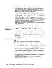
...objects in front of the drive bays has a drive or a filler panel installed in the server, open space around the server to allow the server cooling system to remove it from or install it in it will not support some optional devices. v ...server for the server, see http://www.ibm.com/ servers/eserver/serverproven/compat/us/. v For redundant and hot-swappable power supply operation, the power supplies are finished working on the server. v Microprocessor socket 2 always contains either a heat-sink blank or a microprocessor and heat sink. 10 IBM System x3850 M2 and System x3950 M2...
...objects in front of the drive bays has a drive or a filler panel installed in the server, open space around the server to allow the server cooling system to remove it from or install it in it will not support some optional devices. v ...server for the server, see http://www.ibm.com/ servers/eserver/serverproven/compat/us/. v For redundant and hot-swappable power supply operation, the power supplies are finished working on the server. v Microprocessor socket 2 always contains either a heat-sink blank or a microprocessor and heat sink. 10 IBM System x3850 M2 and System x3950 M2...

Installation Guide
Page 23
... v Avoid wearing loose-fitting clothing on the outside of a grounding system is still in its static-protective package, touch it is necessary to hang inside the server. Follow these guidelines when you work inside a server that might result in their static-protective packages until you are working...not allow your body. Handling static-sensitive devices Attention: Static electricity can damage the server and other grounding system when you are ready to build up around you lean over it. v The use of the server for at least 2 seconds. v Do not leave the device where others can ...
... v Avoid wearing loose-fitting clothing on the outside of a grounding system is still in its static-protective package, touch it is necessary to hang inside the server. Follow these guidelines when you work inside a server that might result in their static-protective packages until you are working...not allow your body. Handling static-sensitive devices Attention: Static electricity can damage the server and other grounding system when you are ready to build up around you lean over it. v The use of the server for at least 2 seconds. v Do not leave the device where others can ...

Installation Guide
Page 25
... 2. Installing optional devices 13 Connect one end of the power supply is turned on, make sure that the power supply is operating correctly. If the server is lit also. Press the orange release latch on the top of the power cord for the new power supply into the bay and fully...
... 2. Installing optional devices 13 Connect one end of the power supply is turned on, make sure that the power supply is operating correctly. If the server is lit also. Press the orange release latch on the top of the power cord for the new power supply into the bay and fully...
Installation Guide
Page 26
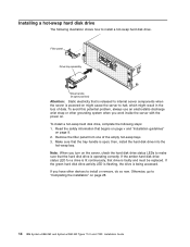
... following illustration shows how to install a hot-swap hard disk drive. Note: When you work inside the server with the power on page 28. 14 IBM System x3850 M2 and System x3950 M2 Types 7141 and 7233: Installation Guide To avoid this potential problem, always use an electrostatic-discharge wrist strap ...or other devices to halt, which might cause the server to install or remove, do so now. then, ...
... following illustration shows how to install a hot-swap hard disk drive. Note: When you work inside the server with the power on page 28. 14 IBM System x3850 M2 and System x3950 M2 Types 7141 and 7233: Installation Guide To avoid this potential problem, always use an electrostatic-discharge wrist strap ...or other devices to halt, which might cause the server to install or remove, do so now. then, ...

Installation Guide
Page 27
Slide the DVD drive into the server until it engages the interposer card or the SATA cable. Chapter 2. Remove the DVD drive filler from the drive bay. 2. Otherwise, go to install or remove, do so now. If you have other devices to "Completing the installation" on page 28. Installing optional devices 15 Installing a DVD drive Retention latch DVD drive DVD filler panel To install a DVD drive, compete the following steps: 1.
Slide the DVD drive into the server until it engages the interposer card or the SATA cable. Chapter 2. Remove the DVD drive filler from the drive bay. 2. Otherwise, go to install or remove, do so now. If you have other devices to "Completing the installation" on page 28. Installing optional devices 15 Installing a DVD drive Retention latch DVD drive DVD filler panel To install a DVD drive, compete the following steps: 1.

Installation Guide
Page 28
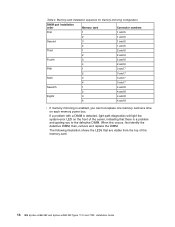
... the User's Guide on the memory card. v The following illustration shows the DIMM connectors on the IBM Documentation CD for the server to operate correctly. DIMM 1 DIMM 2 DIMM 3 DIMM 4 DIMM 5 DIMM 6 DIMM 7 DIMM 8 16 IBM System x3850 M2 and System x3950 M2 Types 7141 and 7233: Installation Guide Installing additional DIMMs The following illustration shows how to install...
... the User's Guide on the memory card. v The following illustration shows the DIMM connectors on the IBM Documentation CD for the server to operate correctly. DIMM 1 DIMM 2 DIMM 3 DIMM 4 DIMM 5 DIMM 6 DIMM 7 DIMM 8 16 IBM System x3850 M2 and System x3950 M2 Types 7141 and 7233: Installation Guide Installing additional DIMMs The following illustration shows how to install...
Installation Guide
Page 30
...defective DIMM; then, remove and replace the DIMM. Table 4. If a problem with a DIMM is detected, light path diagnostics will light the system-error LED on each memory power bus. The following illustration shows the LEDs that there is enabled, you to the defective DIMM. Memory-card ...Eighth 3 4 and 8 4 4 and 8 v If memory mirroring is a problem and guiding you can hot-replace one memory card at a time on the front of the server, indicating that are visible from the top of the memory card. 18 IBM System x3850 M2 and System x3950 M2 Types 7141 and 7233: Installation Guide
...defective DIMM; then, remove and replace the DIMM. Table 4. If a problem with a DIMM is detected, light path diagnostics will light the system-error LED on each memory power bus. The following illustration shows the LEDs that there is enabled, you to the defective DIMM. Memory-card ...Eighth 3 4 and 8 4 4 and 8 v If memory mirroring is a problem and guiding you can hot-replace one memory card at a time on the front of the server, indicating that are visible from the top of the memory card. 18 IBM System x3850 M2 and System x3950 M2 Types 7141 and 7233: Installation Guide

Installation Guide
Page 31
.... 4. Installing a DIMM To install additional DIMMs, complete the following steps: 1. Memory card power LED: When this LED is off the server and peripheral devices, and disconnect the power cords and all external cables as necessary to replace the device. 3. Read the safety information that you can ...
.... 4. Installing a DIMM To install additional DIMMs, complete the following steps: 1. Memory card power LED: When this LED is off the server and peripheral devices, and disconnect the power cords and all external cables as necessary to replace the device. 3. Read the safety information that you can ...
Installation Guide
Page 32
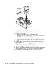
... to touch any unpainted metal surface on a flat, static-protective surface, with the slot. 20 IBM System x3850 M2 and System x3950 M2 Types 7141 and 7233: Installation Guide Slide the orange release latch to any components or structures inside the server. 5. b. Turn the DIMM so that contains the DIMM to the unlocked position. Place the memory...
... to touch any unpainted metal surface on a flat, static-protective surface, with the slot. 20 IBM System x3850 M2 and System x3950 M2 Types 7141 and 7233: Installation Guide Slide the orange release latch to any components or structures inside the server. 5. b. Turn the DIMM so that contains the DIMM to the unlocked position. Place the memory...

Installation Guide
Page 33
...devices to install or remove, do not allow it . If you have other devices to install or remove, do so now. Remove the server cover. Press the memory card into the connector by applying pressure on page 28. Wait 2 seconds and close the small retention lever. 6.... and then reinsert it to "Completing the installation" on the microprocessor board. 5. Otherwise, go to touch any components or structures inside the server. 4. 10. Firmly press the DIMM straight down into the memory-card connector on page 28. Read the safety information that the retention levers ...
...devices to install or remove, do not allow it . If you have other devices to install or remove, do so now. Remove the server cover. Press the memory card into the connector by applying pressure on page 28. Wait 2 seconds and close the small retention lever. 6.... and then reinsert it to "Completing the installation" on the microprocessor board. 5. Otherwise, go to touch any components or structures inside the server. 4. 10. Firmly press the DIMM straight down into the memory-card connector on page 28. Read the safety information that the retention levers ...

Installation Guide
Page 35
... microprocessor socket, if any is present. To install an additional microprocessor, complete the following steps: 1. Turn off the server and peripheral devices, and disconnect the power cords and all external cables as necessary to the fully-open position (approximately 135...and "Installation guidelines" on page 11. 4. Lift the microprocessor-release lever to replace the device. 3. Installing optional devices 23 Remove the server cover and bezel. Captive screws 5. 2. The microprocessor air-baffle must always contain either a heat-sink blank or a microprocessor and heat...
... microprocessor socket, if any is present. To install an additional microprocessor, complete the following steps: 1. Turn off the server and peripheral devices, and disconnect the power cords and all external cables as necessary to the fully-open position (approximately 135...and "Installation guidelines" on page 11. 4. Lift the microprocessor-release lever to replace the device. 3. Installing optional devices 23 Remove the server cover and bezel. Captive screws 5. 2. The microprocessor air-baffle must always contain either a heat-sink blank or a microprocessor and heat...


