Installation Guide
Page 3
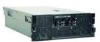
IBM System x3850 M2 and System x3950 M2 Types 7141 and 7233 Installation Guide
IBM System x3850 M2 and System x3950 M2 Types 7141 and 7233 Installation Guide
Installation Guide
Page 6
...Getting help and information from the World Wide Web 77 Software service and support 78 Hardware service and support 78 IBM Taiwan product service 78 Notices 79 Trademarks 79 Important notes 80 Particulate contamination 81 Documentation format 81 Electronic emission notices ...84 Japanese Voluntary Control Council for Interference (VCCI) statement . . . 84 Korean Class A warning statement 84 Index 85 iv IBM System x3850 M2 and System x3950 M2 Types 7141 and 7233: Installation Guide General problems 58 Hard disk drive problems 58 Intermittent problems 59 USB keyboard, mouse, or ...
...Getting help and information from the World Wide Web 77 Software service and support 78 Hardware service and support 78 IBM Taiwan product service 78 Notices 79 Trademarks 79 Important notes 80 Particulate contamination 81 Documentation format 81 Electronic emission notices ...84 Japanese Voluntary Control Council for Interference (VCCI) statement . . . 84 Korean Class A warning statement 84 Index 85 iv IBM System x3850 M2 and System x3950 M2 Types 7141 and 7233: Installation Guide General problems 58 Hard disk drive problems 58 Intermittent problems 59 USB keyboard, mouse, or ...
Installation Guide
Page 8
... statement in this document before you perform the procedures. For example, if a caution statement is labeled "Statement 1," translations for that comes with a number. vi IBM System x3850 M2 and System x3950 M2 Types 7141 and 7233: Installation Guide Read any additional safety information that caution statement are in this document is used to read all caution...
... statement in this document before you perform the procedures. For example, if a caution statement is labeled "Statement 1," translations for that comes with a number. vi IBM System x3850 M2 and System x3950 M2 Types 7141 and 7233: Installation Guide Read any additional safety information that caution statement are in this document is used to read all caution...
Installation Guide
Page 10
... optic devices, or transmitters) are no serviceable parts inside the device. Statement 3: CAUTION: When laser products (such as required by local ordinances or regulations. viii IBM System x3850 M2 and System x3950 M2 Types 7141 and 7233: Installation Guide Laser radiation when open. Statement 2: CAUTION: When replacing the lithium battery, use only...
... optic devices, or transmitters) are no serviceable parts inside the device. Statement 3: CAUTION: When laser products (such as required by local ordinances or regulations. viii IBM System x3850 M2 and System x3950 M2 Types 7141 and 7233: Installation Guide Laser radiation when open. Statement 2: CAUTION: When replacing the lithium battery, use only...

Installation Guide
Page 12
... has this label attached. Statement 26: CAUTION: Do not place any object on a power supply or any component that has the following label attached. x IBM System x3850 M2 and System x3950 M2 Types 7141 and 7233: Installation Guide Statement 8: CAUTION: Never remove the cover on top of these components. If you suspect a problem with one of...
... has this label attached. Statement 26: CAUTION: Do not place any object on a power supply or any component that has the following label attached. x IBM System x3850 M2 and System x3950 M2 Types 7141 and 7233: Installation Guide Statement 8: CAUTION: Never remove the cover on top of these components. If you suspect a problem with one of...
Installation Guide
Page 13
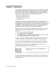
... documentation might be updated occasionally to include information about those features, or technical updates might vary slightly from the IBM Web site. Record information about : v Setting up your IBM® System x3850 M2 and System x3950 M2 Types 7141 and 7233 servers and basic instructions for locating firmware and documentation might be available to provide additional information...
... documentation might be updated occasionally to include information about those features, or technical updates might vary slightly from the IBM Web site. Record information about : v Setting up your IBM® System x3850 M2 and System x3950 M2 Types 7141 and 7233 servers and basic instructions for locating firmware and documentation might be available to provide additional information...
Installation Guide
Page 14
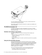
...: v If Autostart is enabled, insert the CD into the CD or DVD drive. The Documentation Browser starts automatically. 2 IBM System x3850 M2 and System x3950 M2 Types 7141 and 7233: Installation Guide ID labels For a list of supported optional devices for that region, the English-language ...version is displayed. Hardware and software requirements The IBM Documentation CD requires the following procedures to browse the contents of ...
...: v If Autostart is enabled, insert the CD into the CD or DVD drive. The Documentation Browser starts automatically. 2 IBM System x3850 M2 and System x3950 M2 Types 7141 and 7233: Installation Guide ID labels For a list of supported optional devices for that region, the English-language ...version is displayed. Hardware and software requirements The IBM Documentation CD requires the following procedures to browse the contents of ...
Installation Guide
Page 16
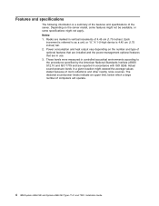
... limit, below which a large number of the server. Features and specifications The following information is a summary of the features and specifications of computers will operate. 4 IBM System x3850 M2 and System x3950 M2 Types 7141 and 7233: Installation Guide
... limit, below which a large number of the server. Features and specifications The following information is a summary of the features and specifications of computers will operate. 4 IBM System x3850 M2 and System x3950 M2 Types 7141 and 7233: Installation Guide
Installation Guide
Page 18
... a component or an orange label on or near a component indicates that the component can be hot-swapped, which means that if the server and operating system support hot-swap capability, you can remove or install the component while the server is running. (Orange can also indicate touch points on . The following... any additional procedures that you might have to perform before you can grip the component to remove it from or install it in the server. 6 IBM System x3850 M2 and System x3950 M2 Types 7141 and 7233: Installation Guide
... a component or an orange label on or near a component indicates that the component can be hot-swapped, which means that if the server and operating system support hot-swap capability, you can remove or install the component while the server is running. (Orange can also indicate touch points on . The following... any additional procedures that you might have to perform before you can grip the component to remove it from or install it in the server. 6 IBM System x3850 M2 and System x3950 M2 Types 7141 and 7233: Installation Guide

Installation Guide
Page 20
Remote Supervisor Adapter II PCI divider with battery holder ServeRAID-MR10k controller and battery Hot-swap power supply Top cover Adapter-retention bracket PCI divider PCI switch-card assembly I/O board shuttle assembly 8 IBM System x3850 M2 and System x3950 M2 Types 7141 and 7233: Installation Guide
Remote Supervisor Adapter II PCI divider with battery holder ServeRAID-MR10k controller and battery Hot-swap power supply Top cover Adapter-retention bracket PCI divider PCI switch-card assembly I/O board shuttle assembly 8 IBM System x3850 M2 and System x3950 M2 Types 7141 and 7233: Installation Guide

Installation Guide
Page 21
... take the opportunity to display the matrix of properly grounded electrical outlets for diagnostic information. v When you . Click System x3850 M2 or System x3950 M2 to download and apply the most recent firmware updates. v If you install optional hardware devices, make sure that the... that your feet. - Never move suddenly or twist when you need more detailed instructions, see the User's Guide on the IBM Documentation CD. Installing optional devices This chapter provides basic instructions for updating, managing, and deploying firmware, see Chapter 6, "Solving ...
... take the opportunity to display the matrix of properly grounded electrical outlets for diagnostic information. v When you . Click System x3850 M2 or System x3950 M2 to download and apply the most recent firmware updates. v If you install optional hardware devices, make sure that the... that your feet. - Never move suddenly or twist when you need more detailed instructions, see the User's Guide on the IBM Documentation CD. Installing optional devices This chapter provides basic instructions for updating, managing, and deploying firmware, see Chapter 6, "Solving ...
Installation Guide
Page 22
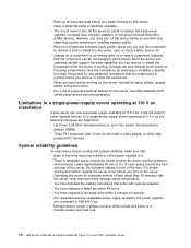
...server. Operating the server for the server, see http://www.ibm.com/ servers/eserver/serverproven/compat/us/. v You do not install a video adapter or other high powered PCI devices System reliability guidelines To help ensure proper cooling and system reliability, make changes to install or replace hot-swap power... you are connected to work properly. v Microprocessor socket 2 always contains either a heat-sink blank or a microprocessor and heat sink. 10 IBM System x3850 M2 and System x3950 M2 Types 7141 and 7233: Installation Guide v When you remove or install the component.
...server. Operating the server for the server, see http://www.ibm.com/ servers/eserver/serverproven/compat/us/. v You do not install a video adapter or other high powered PCI devices System reliability guidelines To help ensure proper cooling and system reliability, make changes to install or replace hot-swap power... you are connected to work properly. v Microprocessor socket 2 always contains either a heat-sink blank or a microprocessor and heat sink. 10 IBM System x3850 M2 and System x3950 M2 Types 7141 and 7233: Installation Guide v When you remove or install the component.
Installation Guide
Page 24
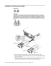
... on the device and the power switch on page 11. 2. Read the safety information that all power cords are disconnected from power-supply bay 2. 12 IBM System x3850 M2 and System x3950 M2 Types 7141 and 7233: Installation Guide Press the blue release latch on the filler-panel handle and pull the handle to the device.
... on the device and the power switch on page 11. 2. Read the safety information that all power cords are disconnected from power-supply bay 2. 12 IBM System x3850 M2 and System x3950 M2 Types 7141 and 7233: Installation Guide Press the blue release latch on the filler-panel handle and pull the handle to the device.
Installation Guide
Page 26
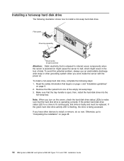
... status LED for a drive is lit continuously, that begins on page v and "Installation guidelines" on page 28. 14 IBM System x3850 M2 and System x3950 M2 Types 7141 and 7233: Installation Guide If you have other grounding system when you turn on the server, check the hard disk drive status LEDs to make sure that is released...
... status LED for a drive is lit continuously, that begins on page v and "Installation guidelines" on page 28. 14 IBM System x3850 M2 and System x3950 M2 Types 7141 and 7233: Installation Guide If you have other grounding system when you turn on the server, check the hard disk drive status LEDs to make sure that is released...

Installation Guide
Page 28
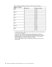
... configuring the server and using the Configuration/Setup Utility program. DIMM 1 DIMM 2 DIMM 3 DIMM 4 DIMM 5 DIMM 6 DIMM 7 DIMM 8 16 IBM System x3850 M2 and System x3950 M2 Types 7141 and 7233: Installation Guide Each server comes with a minimum of one pair of DIMMs must consider when you install DIMMs: v Make sure you...install them in each pair must reconfigure the server by using these features, see the User's Guide on the IBM Documentation CD. See the User's Guide on the IBM Documentation CD for the server to use the hot-add and hot-swap memory features, you must be sure...
... configuring the server and using the Configuration/Setup Utility program. DIMM 1 DIMM 2 DIMM 3 DIMM 4 DIMM 5 DIMM 6 DIMM 7 DIMM 8 16 IBM System x3850 M2 and System x3950 M2 Types 7141 and 7233: Installation Guide Each server comes with a minimum of one pair of DIMMs must consider when you install DIMMs: v Make sure you...install them in each pair must reconfigure the server by using these features, see the User's Guide on the IBM Documentation CD. See the User's Guide on the IBM Documentation CD for the server to use the hot-add and hot-swap memory features, you must be sure...
Installation Guide
Page 30
then, remove and replace the DIMM. If a problem with a DIMM is detected, light path diagnostics will light the system-error LED on each memory power bus. The following illustration shows the LEDs that there is enabled, you to the defective DIMM. Memory-card installation ... hot-replace one memory card at a time on the front of the server, indicating that are visible from the top of the memory card. 18 IBM System x3850 M2 and System x3950 M2 Types 7141 and 7233: Installation Guide When this occurs, first identify the defective DIMM; Table 4.
then, remove and replace the DIMM. If a problem with a DIMM is detected, light path diagnostics will light the system-error LED on each memory power bus. The following illustration shows the LEDs that there is enabled, you to the defective DIMM. Memory-card installation ... hot-replace one memory card at a time on the front of the server, indicating that are visible from the top of the memory card. 18 IBM System x3850 M2 and System x3950 M2 Types 7141 and 7233: Installation Guide When this occurs, first identify the defective DIMM; Table 4.
Installation Guide
Page 32
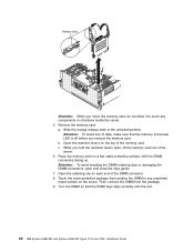
... before you move the memory card, do not allow it to touch any unpainted metal surface on a flat, static-protective surface, with the slot. 20 IBM System x3850 M2 and System x3950 M2 Types 7141 and 7233: Installation Guide b. Release latch Attention: When you remove the memory card. Place the memory card on the server.
... before you move the memory card, do not allow it to touch any unpainted metal surface on a flat, static-protective surface, with the slot. 20 IBM System x3850 M2 and System x3950 M2 Types 7141 and 7233: Installation Guide b. Release latch Attention: When you remove the memory card. Place the memory card on the server.
Installation Guide
Page 34
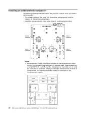
... illustration shows the orientation of these sockets. Fan 4 Fan 1 V R M 3 CPU 3 Fan 5 Fan 2 CPU 4 Fan 6 Fan 3 V R M 4 Memory V Cards R 1 2M 1 CPU 1 CPU 2 V Memory R Cards M3 4 2 22 IBM System x3850 M2 and System x3950 M2 Types 7141 and 7233: Installation Guide Microprocessor sockets 3 and 4 are oriented 180° from each other on the microprocessor board. The following illustration. Be...
... illustration shows the orientation of these sockets. Fan 4 Fan 1 V R M 3 CPU 3 Fan 5 Fan 2 CPU 4 Fan 6 Fan 3 V R M 4 Memory V Cards R 1 2M 1 CPU 1 CPU 2 V Memory R Cards M3 4 2 22 IBM System x3850 M2 and System x3950 M2 Types 7141 and 7233: Installation Guide Microprocessor sockets 3 and 4 are oriented 180° from each other on the microprocessor board. The following illustration. Be...
Installation Guide
Page 36
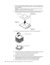
Position the microprocessor over the microprocessor socket as shown in the connector next to the microprocessor socket. 24 IBM System x3850 M2 and System x3950 M2 Types 7141 and 7233: Installation Guide Close the microprocessor-release lever to any unpainted metal surface on the server; Remove the cover from the package. ...
Position the microprocessor over the microprocessor socket as shown in the connector next to the microprocessor socket. 24 IBM System x3850 M2 and System x3950 M2 Types 7141 and 7233: Installation Guide Close the microprocessor-release lever to any unpainted metal surface on the server; Remove the cover from the package. ...
Installation Guide
Page 38
... from the server. 6. The retaining clips snap into the locked position when the controller is seated in the User's Guide on the IBM Documentation CD. Route the battery cable through the cable routing guides on page 9. 2. Installing an adapter Note: For hot-pluggable adapters, make...position. 5. Connect the battery cable to any unpainted metal surface on page 28. If you will use for the adapter. 26 IBM System x3850 M2 and System x3950 M2 Types 7141 and 7233: Installation Guide For details, see the section about installing optional devices in the connector. 11. Install the ...
... from the server. 6. The retaining clips snap into the locked position when the controller is seated in the User's Guide on the IBM Documentation CD. Route the battery cable through the cable routing guides on page 9. 2. Installing an adapter Note: For hot-pluggable adapters, make...position. 5. Connect the battery cable to any unpainted metal surface on page 28. If you will use for the adapter. 26 IBM System x3850 M2 and System x3950 M2 Types 7141 and 7233: Installation Guide For details, see the section about installing optional devices in the connector. 11. Install the ...