User Guide
Page 5
... 56 Using Security Profile by Device 57 Other settings in the IBM Setup Utility program . . 57 The startup sequence 57 Changing the startup sequence 57 Appendix A. Interrupt request and direct memory access channel assignments 67 Appendix E. Overview 1 Identifying your computer 13...computer 11 Locating the connectors on the system board . . . . . 30 Installing memory 31 Installing DIMMs 31 Installing adapters 32 Installing internal drives 33 Drive specifications 34 © Copyright IBM Corp. 2001 Installing a drive 35 Installing a Rope Clip 37 Replacing the cover and ...
... 56 Using Security Profile by Device 57 Other settings in the IBM Setup Utility program . . 57 The startup sequence 57 Changing the startup sequence 57 Appendix A. Interrupt request and direct memory access channel assignments 67 Appendix E. Overview 1 Identifying your computer 13...computer 11 Locating the connectors on the system board . . . . . 30 Installing memory 31 Installing DIMMs 31 Installing adapters 32 Installing internal drives 33 Drive specifications 34 © Copyright IBM Corp. 2001 Installing a drive 35 Installing a Rope Clip 37 Replacing the cover and ...
User Guide
Page 11
.... microtower model" provides instructions for updating the computer configuration, using passwords, and changing the startup sequence. Using the IBM Setup Utility program" provides instructions for removing the cover and installing hard disk drives, memory, and adapters in your computer. v "Appendix B. v "Chapter 2. System address maps" provides information for your computer. v "Appendix E. Installing internal...
.... microtower model" provides instructions for updating the computer configuration, using passwords, and changing the startup sequence. Using the IBM Setup Utility program" provides instructions for removing the cover and installing hard disk drives, memory, and adapters in your computer. v "Appendix B. v "Chapter 2. System address maps" provides information for your computer. v "Appendix E. Installing internal...

User Guide
Page 15
...internal L2 cache memory and Intel NetBurst™ micro-architecture Memory v Support for three dual in-line memory modules (DIMMs) (some models) v 512 KB flash memory for system programs Internal drives v 3.5-inch, 1.44 MB diskette drive ...RPL) and Dynamic Host Configuration Protocol (DHCP) v Wake on LAN v Wake on Ring (in the IBM Setup Utility program, this feature is called Serial Port Ring Detect for an external modem and Modem Ring ...models) Chapter 1. Overview 3 Microprocessor Intel® Pentium™ 4 with 256 KB of the computer features, preinstalled software, and specifications.
...internal L2 cache memory and Intel NetBurst™ micro-architecture Memory v Support for three dual in-line memory modules (DIMMs) (some models) v 512 KB flash memory for system programs Internal drives v 3.5-inch, 1.44 MB diskette drive ...RPL) and Dynamic Host Configuration Protocol (DHCP) v Wake on LAN v Wake on Ring (in the IBM Setup Utility program, this feature is called Serial Port Ring Detect for an external modem and Modem Ring ...models) Chapter 1. Overview 3 Microprocessor Intel® Pentium™ 4 with 256 KB of the computer features, preinstalled software, and specifications.
User Guide
Page 20
...devices Static electricity, although harmless to do not open the static-protective package containing the option until you are some options in -line memory modules (DIMMs) - USB devices, such as printers and external drives - IEEE 1394 devices (requires an IEEE 1394 adapter) -.... v Outside the United States and Canada, contact your computer, you might be needed for the sound system - System memory, called dual in your IBM reseller or IBM marketing representative. Additional tools might need a flat-blade or a Phillips screwdriver. Monitors - Parallel port devices, such as ...
...devices Static electricity, although harmless to do not open the static-protective package containing the option until you are some options in -line memory modules (DIMMs) - USB devices, such as printers and external drives - IEEE 1394 devices (requires an IEEE 1394 adapter) -.... v Outside the United States and Canada, contact your computer, you might be needed for the sound system - System memory, called dual in your IBM reseller or IBM marketing representative. Additional tools might need a flat-blade or a Phillips screwdriver. Monitors - Parallel port devices, such as ...

User Guide
Page 21
Handle adapters and memory modules by the edges. When this is not possible, place the static-protective package that the option came in on a smooth, level surface and place ...
Handle adapters and memory modules by the edges. When this is not possible, place the static-protective package that the option came in on a smooth, level surface and place ...

User Guide
Page 29
...cover up toward the front of your operating system, remove any other cables that come with the option. Shut down your computer by adding memory, drives, or adapters. Disconnect all power cords from the drives, and turn off all attached devices and the computer. 2. Unplug all ... that are connected to the computer. Press the buttons on page 8. small desktop model You can expand the capabilities of the computer. © Copyright IBM Corp. 2001 17 To remove the cover: 1. This includes power cords, input/output (I/O) cables, and any media (diskettes, CDs, or tapes) from...
...cover up toward the front of your operating system, remove any other cables that come with the option. Shut down your computer by adding memory, drives, or adapters. Disconnect all power cords from the drives, and turn off all attached devices and the computer. 2. Unplug all ... that are connected to the computer. Press the buttons on page 8. small desktop model You can expand the capabilities of the computer. © Copyright IBM Corp. 2001 17 To remove the cover: 1. This includes power cords, input/output (I/O) cables, and any media (diskettes, CDs, or tapes) from...

User Guide
Page 31
...starting at DIMM 1 v Use 3.3 V, synchronous, 168-pin, unbuffered, 133 MHz, nonparity, synchronous dynamic random access memory (SDRAM) v Use 64 MB, 128 MB, 256 MB, or 512 MB DIMMs in -line memory modules (DIMMs) that provide up to mechanical restrictions. Installing internal options - small desktop model 19 See "Removing the cover...LED connector 11 PCI slots 12 Front panel audio connector 13 CD-ROM audio connector 14 AGP slot 15 12V Power connector Installing memory Your computer has three connectors for installing dual in any combination v DIMM heights of 38.1 mm (1.5 inches) To install ...
...starting at DIMM 1 v Use 3.3 V, synchronous, 168-pin, unbuffered, 133 MHz, nonparity, synchronous dynamic random access memory (SDRAM) v Use 64 MB, 128 MB, 256 MB, or 512 MB DIMMs in -line memory modules (DIMMs) that provide up to mechanical restrictions. Installing internal options - small desktop model 19 See "Removing the cover...LED connector 11 PCI slots 12 Front panel audio connector 13 CD-ROM audio connector 14 AGP slot 15 12V Power connector Installing memory Your computer has three connectors for installing dual in any combination v DIMM heights of 38.1 mm (1.5 inches) To install ...

User Guide
Page 41
When installing an option, use these instructions along with the option. Shut down your computer by adding memory, drives, or adapters. Chapter 4. Press the buttons on page 8 before removing the cover. Disconnect all power cords from the drives, and turn off all attached ... other cables that come with the instructions that are connected to the computer. desktop model You can expand the capabilities of the computer. © Copyright IBM Corp. 2001 29 To remove the cover: 1. Installing internal options - Unplug all cables attached to the computer. 4.
When installing an option, use these instructions along with the option. Shut down your computer by adding memory, drives, or adapters. Chapter 4. Press the buttons on page 8 before removing the cover. Disconnect all power cords from the drives, and turn off all attached ... other cables that come with the instructions that are connected to the computer. desktop model You can expand the capabilities of the computer. © Copyright IBM Corp. 2001 29 To remove the cover: 1. Installing internal options - Unplug all cables attached to the computer. 4.

User Guide
Page 43
..., starting at DIMM 1 v Use 3.3 V, synchronous, 168-pin, unbuffered, 133 MHz nonparity synchronous dynamic random access memory (SDRAM) v Use 64 MB, 128 MB, 256 MB, or 512 MB DIMMs in -line memory modules (DIMMs) that provide up to the DIMM slots. Chapter 4. See "Removing the cover" on page 32....panel audio connector 13 CD-ROM audio connector 14 AGP slot 15 12V Power connector Installing memory Your computer has three connectors for installing dual in any combination v DIMM heights of system memory. Remove the cover. See "Installing adapters" on page 29. 2. Installing internal options...
..., starting at DIMM 1 v Use 3.3 V, synchronous, 168-pin, unbuffered, 133 MHz nonparity synchronous dynamic random access memory (SDRAM) v Use 64 MB, 128 MB, 256 MB, or 512 MB DIMMs in -line memory modules (DIMMs) that provide up to the DIMM slots. Chapter 4. See "Removing the cover" on page 32....panel audio connector 13 CD-ROM audio connector 14 AGP slot 15 12V Power connector Installing memory Your computer has three connectors for installing dual in any combination v DIMM heights of system memory. Remove the cover. See "Installing adapters" on page 29. 2. Installing internal options...

User Guide
Page 53
When installing an option, use these instructions along with the option. Shut down your computer by adding memory, drives, or adapters. Disconnect all attached devices and the computer. 2. Press the cover release button on page 8 before removing the ... the cover Important: Read "Safety Information" on page v and "Handling static-sensitive devices" on the left side cover and remove the cover. © Copyright IBM Corp. 2001 41 Installing internal options - To remove the cover: 1. Chapter 5. This includes power cords, input/output (I/O) cables, and any media (diskettes,...
When installing an option, use these instructions along with the option. Shut down your computer by adding memory, drives, or adapters. Disconnect all attached devices and the computer. 2. Press the cover release button on page 8 before removing the ... the cover Important: Read "Safety Information" on page v and "Handling static-sensitive devices" on the left side cover and remove the cover. © Copyright IBM Corp. 2001 41 Installing internal options - To remove the cover: 1. Chapter 5. This includes power cords, input/output (I/O) cables, and any media (diskettes,...

User Guide
Page 56
... starting at DIMM 1 v Use 3.3 V, synchronous, 168-pin, unbuffered, 133 MHz nonparity synchronous dynamic random access memory (SDRAM) v Use 64 MB, 128 MB, 256 MB, or 512 MB DIMMs in -line memory modules (DIMMs) that provide up to the DIMM slots. Installing DIMMs When installing DIMMs, the following illustration for the...10 SCSI LED connector 11 PCI slots 12 Front panel audio connector 13 CD-ROM audio connector 14 AGP slot 15 12V Power connector Installing memory Your computer has three connectors for installing dual in any combination v DIMM heights of 38.1 mm (1.5 inches) To install a DIMM:...
... starting at DIMM 1 v Use 3.3 V, synchronous, 168-pin, unbuffered, 133 MHz nonparity synchronous dynamic random access memory (SDRAM) v Use 64 MB, 128 MB, 256 MB, or 512 MB DIMMs in -line memory modules (DIMMs) that provide up to the DIMM slots. Installing DIMMs When installing DIMMs, the following illustration for the...10 SCSI LED connector 11 PCI slots 12 Front panel audio connector 13 CD-ROM audio connector 14 AGP slot 15 12V Power connector Installing memory Your computer has three connectors for installing dual in any combination v DIMM heights of 38.1 mm (1.5 inches) To install a DIMM:...

User Guide
Page 67
...press F1. (This prompt is displayed for your computer and data. The IBM Setup Utility might override any similar settings in your password. The keys used to set a password of either one, read -only memory (EEPROM) of passwords: a user password and an administrator password. Viewing... and changing settings The IBM Setup Utility program menu lists items that hardware has been removed or new hardware has been...
...press F1. (This prompt is displayed for your computer and data. The IBM Setup Utility might override any similar settings in your password. The keys used to set a password of either one, read -only memory (EEPROM) of passwords: a user password and an administrator password. Viewing... and changing settings The IBM Setup Utility program menu lists items that hardware has been removed or new hardware has been...
User Guide
Page 71
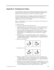
Refer to "Lithium battery notice" on page vi for information about replacing and disposing of memory that maintains the date, time, and settings for built-in the power cord. See "Removing the cover" on page 17 (small desktop model), "Removing the ...cover" on page 29 (desktop model), or "Removing the cover" on page 52 (microtower model). © Copyright IBM Corp. 2001 59 Locate the battery. See "Installing adapters" on page 20 (small desktop model), "Installing adapters" on page 32 (desktop model), or "Installing adapters...
Refer to "Lithium battery notice" on page vi for information about replacing and disposing of memory that maintains the date, time, and settings for built-in the power cord. See "Removing the cover" on page 17 (small desktop model), "Removing the ...cover" on page 29 (desktop model), or "Removing the cover" on page 52 (microtower model). © Copyright IBM Corp. 2001 59 Locate the battery. See "Installing adapters" on page 20 (small desktop model), "Installing adapters" on page 32 (desktop model), or "Installing adapters...

User Guide
Page 73
... layer of tests and procedures that translates instructions from a POST/BIOS update failure If power to pins 2 and 3. © Copyright IBM Corp. 2001 61 Insert a system program update (flash) diskette into your computer. The update begins. If this happens, perform the ...all power cords from a POST/BIOS update failure. Appendix B. Your computer system board has a module called electrically erasable programmable read-only memory (EEPROM, also referred to recover from electrical outlets, and remove the cover. Updating System Programs The following procedure to the Clear CMOS/...
... layer of tests and procedures that translates instructions from a POST/BIOS update failure If power to pins 2 and 3. © Copyright IBM Corp. 2001 61 Insert a system program update (flash) diskette into your computer. The update begins. If this happens, perform the ...all power cords from a POST/BIOS update failure. Appendix B. Your computer system board has a module called electrically erasable programmable read-only memory (EEPROM, also referred to recover from electrical outlets, and remove the cover. Updating System Programs The following procedure to the Clear CMOS/...

User Guide
Page 75
... 768 K - 800 KB C0000 - Address ranges and byte sizes are reserved. FFDFFFFF FFFE0000 - A 256-byte area and a 1 KB area of system board RAM is mapped starting at address hex 00000000. FFFFFF 16 MB - 4096 MB 10000000 - FFFFFFFF Size 512 KB 127 KB 1 KB 128 KB 32 KB 96 KB 128 KB... B Keyboard controller, CMD/ATAT byte Enable NMI Real-time clock, address Real-time clock, data © Copyright IBM Corp. 2001 63 System memory map The first 640 KB of this RAM are reserved for the I /O address map The following charts represent how the hard disk stores different types of information...
... 768 K - 800 KB C0000 - Address ranges and byte sizes are reserved. FFDFFFFF FFFE0000 - A 256-byte area and a 1 KB area of system board RAM is mapped starting at address hex 00000000. FFFFFF 16 MB - 4096 MB 10000000 - FFFFFFFF Size 512 KB 127 KB 1 KB 128 KB 32 KB 96 KB 128 KB... B Keyboard controller, CMD/ATAT byte Enable NMI Real-time clock, address Real-time clock, data © Copyright IBM Corp. 2001 63 System memory map The first 640 KB of this RAM are reserved for the I /O address map The following charts represent how the hard disk stores different types of information...

User Guide
Page 77
... control register Available DMA I /O address map Address (hex) Description 0000 Channel 0, memory address register 0001 Channel 0, transfer count register 0002 Channel 1, memory address register 0003 Channel 1, transfer count register 0004 Channel 2, memory address register 0005 Channel 2, transfer count register 0006 Channel 3, memory address register 0007 Channel 3, transfer count register 0008 Channels 0-3, read status/write...
... control register Available DMA I /O address map Address (hex) Description 0000 Channel 0, memory address register 0001 Channel 0, transfer count register 0002 Channel 1, memory address register 0003 Channel 1, transfer count register 0004 Channel 2, memory address register 0005 Channel 2, transfer count register 0006 Channel 3, memory address register 0007 Channel 3, transfer count register 0008 Channels 0-3, read status/write...

User Guide
Page 78
... table address register 008F Channel 4, page table address/refresh register 00C0 Channel 4, memory address register 00C2 Channel 4, transfer count register 00C4 Channel 5, memory address register 00C6 Channel 5, transfer count register 00C8 Channel 6, memory address register 00CA Channel 6, transfer count register 00CC Channel 7, memory address register 00CE Channel 7, transfer count register 00D0 Channels 4-7, read status...
... table address register 008F Channel 4, page table address/refresh register 00C0 Channel 4, memory address register 00C2 Channel 4, transfer count register 00C4 Channel 5, memory address register 00C6 Channel 5, transfer count register 00C8 Channel 6, memory address register 00CA Channel 6, transfer count register 00CC Channel 7, memory address register 00CE Channel 7, transfer count register 00D0 Channels 4-7, read status...

User Guide
Page 79
... only) COM1 Available to user Diskette controller LPT1 Real-time clock Video, ACPI Available to user Available to another IRQ. Table 5. Interrupt request and direct memory access channel assignments The following tables list the IRQ and DMA channel assignments. DMA channel assignments DMA channel 0 1 2 3 4 5 6 7 Data width 8 bits 8 bits 8 bits 8 bits 16... coprocessor Primary IDE (if present) Secondary IDE (if present) Note: The default settings for ECP or EPP) Reserved (cascade channel) Open Open Open © Copyright IBM Corp. 2001 67
... only) COM1 Available to user Diskette controller LPT1 Real-time clock Video, ACPI Available to user Available to another IRQ. Table 5. Interrupt request and direct memory access channel assignments The following tables list the IRQ and DMA channel assignments. DMA channel assignments DMA channel 0 1 2 3 4 5 6 7 Data width 8 bits 8 bits 8 bits 8 bits 16... coprocessor Primary IDE (if present) Secondary IDE (if present) Note: The default settings for ECP or EPP) Reserved (cascade channel) Open Open Open © Copyright IBM Corp. 2001 67

User Guide
Page 83
... 13, 14, 15, 16 I IBM Setup Utility 55 input/output (I/O) address map 63, 65 DMA address map 65 features 3 installing options desktop model adapters 32 DIMMs 31 internal drives 35 memory 31 Rope Clip 37 microtower model adapters 45 DIMMs 44 internal drives 48 memory 44 Rope Clip 51 small desktop...(IRQ) channel assignments 67 K keyboard connector 13, 14, 15, 16 L locating components desktop model 30 microtower model 42 small desktop model 18 M memory dual in-line memory-modules (DIMMs) installing 19, 31, 44 map 63 system 8, 19, 44 microphone connector 13, 14, 15, 16 mouse connector 13, 14,...
... 13, 14, 15, 16 I IBM Setup Utility 55 input/output (I/O) address map 63, 65 DMA address map 65 features 3 installing options desktop model adapters 32 DIMMs 31 internal drives 35 memory 31 Rope Clip 37 microtower model adapters 45 DIMMs 44 internal drives 48 memory 44 Rope Clip 51 small desktop...(IRQ) channel assignments 67 K keyboard connector 13, 14, 15, 16 L locating components desktop model 30 microtower model 42 small desktop model 18 M memory dual in-line memory-modules (DIMMs) installing 19, 31, 44 map 63 system 8, 19, 44 microphone connector 13, 14, 15, 16 mouse connector 13, 14,...
User Guide
Page 84
... serial connectors 13, 14, 15, 16 system address maps 63 system board connectors 19, 31, 44 identifying parts 18, 30, 43 location 19, 31, 44 memory 8, 18, 31, 43 system programs, updating 61 U updating system programs 61 USB connectors 13, 14, 15, 16 using, security profile by device 57 V video, subsystem...
... serial connectors 13, 14, 15, 16 system address maps 63 system board connectors 19, 31, 44 identifying parts 18, 30, 43 location 19, 31, 44 memory 8, 18, 31, 43 system programs, updating 61 U updating system programs 61 USB connectors 13, 14, 15, 16 using, security profile by device 57 V video, subsystem...


