
Service Guide
Page 7
...-size cash drawer FRUs - disassembling 118 IBM 4610 SureMark printers - removal 122 4610 SureMark printer - Parts catalog Assembly 1: System parts Assembly 2: System board Assembly 3: Wall Mount feature parts Assembly 4: Optional features Assembly 5: Countertop non-keyboard integration tray and filler panels . . . Power Cords 167 Power cords 167 Appendix C. SurePOS 500 Models 5x3 and 544/564 tips 189...
...-size cash drawer FRUs - disassembling 118 IBM 4610 SureMark printers - removal 122 4610 SureMark printer - Parts catalog Assembly 1: System parts Assembly 2: System board Assembly 3: Wall Mount feature parts Assembly 4: Optional features Assembly 5: Countertop non-keyboard integration tray and filler panels . . . Power Cords 167 Power cords 167 Appendix C. SurePOS 500 Models 5x3 and 544/564 tips 189...
Service Guide
Page 8
...-Hebrew 208 Safety Information-Korean 210 Safety Information-Italian 213 Safety Information-Spanish 216 Safety Information-German 218 Safety Information-Traditional Chinese 220 Index 223 Part number index 231 vi Notices 191 Intel software license agreement (final, single user 193 Copyright license 193 Ownership of software and copyrights 193 Limited media...
...-Hebrew 208 Safety Information-Korean 210 Safety Information-Italian 213 Safety Information-Spanish 216 Safety Information-German 218 Safety Information-Traditional Chinese 220 Index 223 Part number index 231 vi Notices 191 Intel software license agreement (final, single user 193 Copyright license 193 Ownership of software and copyrights 193 Limited media...
Service Guide
Page 13
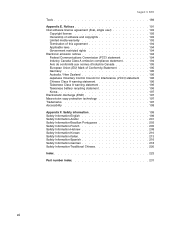
... IBM Corp. 2004, 2006 xi PS/2 keyboard/mouse port assignment 15 5. SurePOS 500 Series dimensions 170 15. SurePOS 500 Series...touch screen 17 6. SurePOS 500 Models 5x3 and 544/564 task information 25 7. Keyboard part numbers 137 13. Default... serial-port assignments 15 3. Assignments for 15-pin serial connector 183 31. Ethernet connector-pin assignments 184 34. Assignment of cash drawer connector pins 186 36. Power cords 167 14. Unit dimensions 175 17. Power consumption 178 21. Assignment of parallel-connector pins 183 32...
... IBM Corp. 2004, 2006 xi PS/2 keyboard/mouse port assignment 15 5. SurePOS 500 Series dimensions 170 15. SurePOS 500 Series...touch screen 17 6. SurePOS 500 Models 5x3 and 544/564 task information 25 7. Keyboard part numbers 137 13. Default... serial-port assignments 15 3. Assignments for 15-pin serial connector 183 31. Ethernet connector-pin assignments 184 34. Assignment of cash drawer connector pins 186 36. Power cords 167 14. Unit dimensions 175 17. Power consumption 178 21. Assignment of parallel-connector pins 183 32...
Service Guide
Page 22
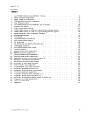
... weather because heating reduces indoor humidity and increases static electricity. August 3, 2006 Mercury-added statement The fluorescent lamp in . (46 cm.) to an unpainted metal part of electrostatic discharge, observe the following precautions: v Limit your system. Dispose of it as required by its edges or its package and install it to...
... weather because heating reduces indoor humidity and increases static electricity. August 3, 2006 Mercury-added statement The fluorescent lamp in . (46 cm.) to an unpainted metal part of electrostatic discharge, observe the following precautions: v Limit your system. Dispose of it as required by its edges or its package and install it to...
Service Guide
Page 23
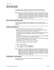
references to Model 543 also apply to Model W73; references to Model 573 also apply to Model W43; v IBM SurePOS 500 Series Planning, Installation, and Operation Guide for Models 533, 543, 544, 553, 563, 564, 573, and 5A3, SY27-...the system unit, including parts listings, troubleshooting, and removal and replacement procedures. August 3, 2006 About this guide and other related publications are accessibility-enabled. © Copyright IBM Corp. 2004, 2006 xxi Publications accessibility The soft-copy version of the following publications: v IBM SurePOS 500 Series Hardware Service Guide ...
references to Model 543 also apply to Model W73; references to Model 573 also apply to Model W43; v IBM SurePOS 500 Series Planning, Installation, and Operation Guide for Models 533, 543, 544, 553, 563, 564, 573, and 5A3, SY27-...the system unit, including parts listings, troubleshooting, and removal and replacement procedures. August 3, 2006 About this guide and other related publications are accessibility-enabled. © Copyright IBM Corp. 2004, 2006 xxi Publications accessibility The soft-copy version of the following publications: v IBM SurePOS 500 Series Hardware Service Guide ...
Service Guide
Page 24
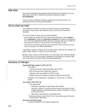
...required in helping us what you think about Diagnostic programs | v Changes a field replaceable unit (FRU) number | v Deletes reference to an IBM representative. Select the publication comments link within the introductory text. If applicable, include a reference to the specific location of the text (for ...the Publication ID field. Be sure to SY27-0417-02 v This update adds: - Select Support, then Publications. v Moved cash drawer parts to the "Point of Sale Options and I/O Devices Service Guide," GC30-9737 November 2005 Web update Inserted the latest End of these ways ...
...required in helping us what you think about Diagnostic programs | v Changes a field replaceable unit (FRU) number | v Deletes reference to an IBM representative. Select the publication comments link within the introductory text. If applicable, include a reference to the specific location of the text (for ...the Publication ID field. Be sure to SY27-0417-02 v This update adds: - Select Support, then Publications. v Moved cash drawer parts to the "Point of Sale Options and I/O Devices Service Guide," GC30-9737 November 2005 Web update Inserted the latest End of these ways ...
Service Guide
Page 44
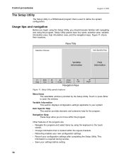
Setup Utility panels have four parts: selection area, variable information area, help for the program. Figure 11 shows their locations. Setup Utility panels locations Menu Items The selectable windows provided by ...
Setup Utility panels have four parts: selection area, variable information area, help for the program. Figure 11 shows their locations. Setup Utility panels locations Menu Items The selectable windows provided by ...
Service Guide
Page 51
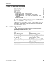
... service call by performing the appropriate task listed in Table 6. "Running Diagnostics" on page 189. © Copyright IBM Corp. 2004, 2006 25 Appendix D, "SurePOS 500 Models 5x3 and 544/564 tips," on page 30 Look up a part number. Start problem diagnosis here If you determine the cause of a problem and resolve it. "Preliminary checklist...
... service call by performing the appropriate task listed in Table 6. "Running Diagnostics" on page 189. © Copyright IBM Corp. 2004, 2006 25 Appendix D, "SurePOS 500 Models 5x3 and 544/564 tips," on page 30 Look up a part number. Start problem diagnosis here If you determine the cause of a problem and resolve it. "Preliminary checklist...
Service Guide
Page 61
..., touch it and your system, without putting it component side up.) Do not place the device onto the cover of the system unit for the SurePOS 500 Models 5x3 and 544/564 35 August 3, 2006 Removing and replacing v Do not touch solder joints, pins, or exposed printed circuitry. v While the ...care when handling devices during cold weather because heating reduces indoor humidity and increases static electricity. If it is necessary to an unpainted metal part of the system or onto a metal table. Chapter 4. v Do not leave the device where others can handle and possibly damage the device...
..., touch it and your system, without putting it component side up.) Do not place the device onto the cover of the system unit for the SurePOS 500 Models 5x3 and 544/564 35 August 3, 2006 Removing and replacing v Do not touch solder joints, pins, or exposed printed circuitry. v While the ...care when handling devices during cold weather because heating reduces indoor humidity and increases static electricity. If it is necessary to an unpainted metal part of the system or onto a metal table. Chapter 4. v Do not leave the device where others can handle and possibly damage the device...

Service Guide
Page 79
...replacing Note: When replacing the LED card, make sure you replace with the correct part number. Remove the front cover as described at "Power supply - b. Chapter 4. Remove the power supply as described at "Rear cover - Figure 32. Unplug the power cord from the LED card. 4. Disconnect the speaker cable and...This step is required only if the LED card cable is present it out from the LED card (see Figure 32) and remove it. 5. If a presence sensor is to the SurePOS 500 Models 5x3 and 544/564. removing and replacing" on page 57. Remove the two screws from the front ...
...replacing Note: When replacing the LED card, make sure you replace with the correct part number. Remove the front cover as described at "Power supply - b. Chapter 4. Remove the power supply as described at "Rear cover - Figure 32. Unplug the power cord from the LED card. 4. Disconnect the speaker cable and...This step is required only if the LED card cable is present it out from the LED card (see Figure 32) and remove it. 5. If a presence sensor is to the SurePOS 500 Models 5x3 and 544/564. removing and replacing" on page 57. Remove the two screws from the front ...
Service Guide
Page 91
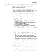
...normal operation. a. The new system board comes with a new battery. removing and replacing" on page 78. 6. Transfer modules to the SurePOS 500 Models 5x3 and 544/564. Remove jumpers JP29-JP35 from the system board. 7. removing and replacing Attention: Establish personal grounding before replacing...System board - See "Electrostatic discharge (ESD)" on page 69. Disconnect all required jumpers and with factory default CMOS settings. Install these parts on page 22. 2. When replacing the system board, you can usually save the CMOS settings by the fansink and slide it out ...
...normal operation. a. The new system board comes with a new battery. removing and replacing" on page 78. 6. Transfer modules to the SurePOS 500 Models 5x3 and 544/564. Remove jumpers JP29-JP35 from the system board. 7. removing and replacing Attention: Establish personal grounding before replacing...System board - See "Electrostatic discharge (ESD)" on page 69. Disconnect all required jumpers and with factory default CMOS settings. Install these parts on page 22. 2. When replacing the system board, you can usually save the CMOS settings by the fansink and slide it out ...

Service Guide
Page 93
... pin location: Description JP7 pins 1-2 CMOS Memory clear - Remove the system board. Remove the two screws attaching the side I/O EMC shield to the SurePOS 500 Models 5x3 and 544/564. Switch OFF the power to the system board. Unplug the power cord from these pins JP6 pins 1-2 If JP6 header...- Table 8. removing and replacing 1. All jumper pins have the pin number printed on all jumpers from the external power source. 2. removing and replacing This part is indicated on the system board for the SurePOS 500 Models 5x3 and 544/564 67 removing and replacing" on page 78. 4.
... pin location: Description JP7 pins 1-2 CMOS Memory clear - Remove the system board. Remove the two screws attaching the side I/O EMC shield to the SurePOS 500 Models 5x3 and 544/564. Switch OFF the power to the system board. Unplug the power cord from these pins JP6 pins 1-2 If JP6 header...- Table 8. removing and replacing 1. All jumper pins have the pin number printed on all jumpers from the external power source. 2. removing and replacing This part is indicated on the system board for the SurePOS 500 Models 5x3 and 544/564 67 removing and replacing" on page 78. 4.

Service Guide
Page 161
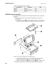
... new key definition. Replace the keyboard logic board. The 32 programmable keys are failing (keyboard is not operational). The part number for the CANPOS Keyboard. Replace the keyboard logic board. © Copyright IBM Corp. 2004, 2006 135 August 3, 2006 Chapter 5. Keyboard... is attached. The CANPOS Keyboard provides a QWERTY layout, an integrated pointing device, a numeric keypad, and 32 programmable keys. See the SurePOS 500/600 Installation and Operations Guide for more information on page 141. Customers outside the U.S. Replace the keypad assembly...
... new key definition. Replace the keyboard logic board. The 32 programmable keys are failing (keyboard is not operational). The part number for the CANPOS Keyboard. Replace the keyboard logic board. © Copyright IBM Corp. 2004, 2006 135 August 3, 2006 Chapter 5. Keyboard... is attached. The CANPOS Keyboard provides a QWERTY layout, an integrated pointing device, a numeric keypad, and 32 programmable keys. See the SurePOS 500/600 Installation and Operations Guide for more information on page 141. Customers outside the U.S. Replace the keypad assembly...

Service Guide
Page 163
... Customers outside the U.S. If you have one of these keyboards, you have this style cap, replacement caps (part number 30R0037) can be replaced. and Canada should be purchased by calling 1-800-IBM-CALL (1-800-426-2255) in the following table are no longer available; removing and replacing Figure 109 shows... the CANPOS keyboard and its components: MSR 32 Programmable Keys Esc F1 F2 F3 F4 F5 F6 F7 F8 F9...
... Customers outside the U.S. If you have one of these keyboards, you have this style cap, replacement caps (part number 30R0037) can be replaced. and Canada should be purchased by calling 1-800-IBM-CALL (1-800-426-2255) in the following table are no longer available; removing and replacing Figure 109 shows... the CANPOS keyboard and its components: MSR 32 Programmable Keys Esc F1 F2 F3 F4 F5 F6 F7 F8 F9...
Service Guide
Page 164
... the keyboard integration tray by lifting the keyboard up and off the keyboard integration tray, as show in the CANPOS keyboard keypad assembly: 138 c. Keyboard part numbers (continued) Keyboard P/N Description 54P8790 Spanish 54P8791 Brazilian Portuguese 54P8792 German August 3, 2006 MSR Yes Yes Yes CANPOS keypad assembly You must remove the keyboard...
... the keyboard integration tray by lifting the keyboard up and off the keyboard integration tray, as show in the CANPOS keyboard keypad assembly: 138 c. Keyboard part numbers (continued) Keyboard P/N Description 54P8790 Spanish 54P8791 Brazilian Portuguese 54P8792 German August 3, 2006 MSR Yes Yes Yes CANPOS keypad assembly You must remove the keyboard...
Service Guide
Page 171
... . 152 . 154 156 . 158 . 160 . 162 . 164 This chapter contains part number information for the FRUs that are part of the SurePOS 500 Models 5x3 and 544/564. © Copyright IBM Corp. 2004, 2006 145 Parts catalog Assembly 1: System parts Assembly 2: System board Assembly 3: Wall Mount feature parts Assembly 4: Optional features Assembly 5: Countertop non-keyboard integration tray and...
... . 152 . 154 156 . 158 . 160 . 162 . 164 This chapter contains part number information for the FRUs that are part of the SurePOS 500 Models 5x3 and 544/564. © Copyright IBM Corp. 2004, 2006 145 Parts catalog Assembly 1: System parts Assembly 2: System board Assembly 3: Wall Mount feature parts Assembly 4: Optional features Assembly 5: Countertop non-keyboard integration tray and...
Service Guide
Page 173
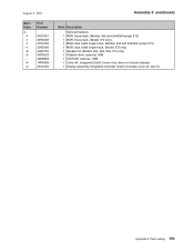
...no speaker 1 Cover, front, hard disk drive - Index 1- -1 - -2 - -4 -5 -6 -7 -8 -9 - -10 -11 -12 -12 -13 - - -14 -15 - -16 - -17 -18 Part Number 99P9839 39V5018 14R1999 39V5099 40N5653 40N5812 41D0136 47P6415 14R0013 40N5693 40N5692 14R0009 14R0015 14R1989 39V5019 99P9842 99P9843 39V5098 41D0148 41D0146 14R0007 40N5700 39V5085 14R1996...see Assembly 2 1 HDD, 40 GB Fan, HDD with mounting bracket (Model 573 only) (not shown) 1 Speaker kit 1 ESD shield 1 CompactFlash, 512 MB (not shown) 1 Cable kit, HDD (not shown) 1 Kit, screw (not shown) 1 Kit, tablet stand adapter (Model 573 only) (not shown)...
...no speaker 1 Cover, front, hard disk drive - Index 1- -1 - -2 - -4 -5 -6 -7 -8 -9 - -10 -11 -12 -12 -13 - - -14 -15 - -16 - -17 -18 Part Number 99P9839 39V5018 14R1999 39V5099 40N5653 40N5812 41D0136 47P6415 14R0013 40N5693 40N5692 14R0009 14R0015 14R1989 39V5019 99P9842 99P9843 39V5098 41D0148 41D0146 14R0007 40N5700 39V5085 14R1996...see Assembly 2 1 HDD, 40 GB Fan, HDD with mounting bracket (Model 573 only) (not shown) 1 Speaker kit 1 ESD shield 1 CompactFlash, 512 MB (not shown) 1 Cable kit, HDD (not shown) 1 Kit, screw (not shown) 1 Kit, tablet stand adapter (Model 573 only) (not shown)...
Service Guide
Page 177
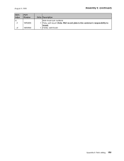
August 3, 2006 Asm- Parts catalog 151 Index 3- -1 Part Number 14R0096 -2 14R0094 Assembly 3: (continued) Units Description Wall mount part numbers 1 Plate, wall mount (Note: Wall mount plate is the customer's responsibility to install) 1 Frame, wall mount Appendix A.
August 3, 2006 Asm- Parts catalog 151 Index 3- -1 Part Number 14R0096 -2 14R0094 Assembly 3: (continued) Units Description Wall mount part numbers 1 Plate, wall mount (Note: Wall mount plate is the customer's responsibility to install) 1 Frame, wall mount Appendix A.
Service Guide
Page 179
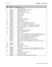
... August 3, 2006 Asm- Index 4- -1 -1 -1 -1 -2 -3 - -4 -5 Part Number 41D0151 39V5068 41D0152 39V5069 40N5755 06P5223 42M5864 14R0029 41D0149 Assembly 4: (continued) Units Description Optional features 1 MSR, three-track, (Models 5x3 and 544/564 except ...
... August 3, 2006 Asm- Index 4- -1 -1 -1 -1 -2 -3 - -4 -5 Part Number 41D0151 39V5068 41D0152 39V5069 40N5755 06P5223 42M5864 14R0029 41D0149 Assembly 4: (continued) Units Description Optional features 1 MSR, three-track, (Models 5x3 and 544/564 except ...

Service Guide
Page 181
... includes feet and screws, not illustrated) 1 FRU, printer filler panel kit, non-keyboard (not shown) 1 Feet, rubber (5) Appendix A. Index 5- -1 -1 -2 -3 -4 - Part Number 41D0261 41D0213 41D0211 41D0207 14R1998 41D0212 - 41D0209 -5 93F0663 Assembly 5: (continued) Units Description Countertop non-keyboard integration tray and filler panels 1 Plate and fence, countertop ...
... includes feet and screws, not illustrated) 1 FRU, printer filler panel kit, non-keyboard (not shown) 1 Feet, rubber (5) Appendix A. Index 5- -1 -1 -2 -3 -4 - Part Number 41D0261 41D0213 41D0211 41D0207 14R1998 41D0212 - 41D0209 -5 93F0663 Assembly 5: (continued) Units Description Countertop non-keyboard integration tray and filler panels 1 Plate and fence, countertop ...
