
Installation Guide
Page 1
...57443;e bottom of the outlet box is recessed a minimum of the fan. Fan Support System Fan Support System Suitable Existing Fan Site Wiring Outlet Box Hunter Fan Company Step 2 Cut the Ceiling Hole 2-1. You will use an existing fan site, complete the following checklist to determine if the site is ...acceptable and safe for Existing Fan Site If you are unfamiliar with wiring, use a ...
...57443;e bottom of the outlet box is recessed a minimum of the fan. Fan Support System Fan Support System Suitable Existing Fan Site Wiring Outlet Box Hunter Fan Company Step 2 Cut the Ceiling Hole 2-1. You will use an existing fan site, complete the following checklist to determine if the site is ...acceptable and safe for Existing Fan Site If you are unfamiliar with wiring, use a ...
Owner's Manual
Page 2
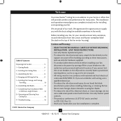
Welcome Your new Hunter® ceiling fan is complete. © 2011 Hunter Fan Company 2 42609-01 • 01/12/11 • Hunter Fan Company Never insert foreign objects between rotating fan blades. • To reduce the risk of the building according to the support structure of fire, electrical shock, or motor damage, do not bend the ...
Welcome Your new Hunter® ceiling fan is complete. © 2011 Hunter Fan Company 2 42609-01 • 01/12/11 • Hunter Fan Company Never insert foreign objects between rotating fan blades. • To reduce the risk of the building according to the support structure of fire, electrical shock, or motor damage, do not bend the ...
Owner's Manual
Page 3
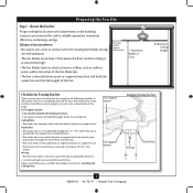
... Wall or Nearest Obstruction 7' Minimum Blades to Section 2 • Installing the Ceiling Plate. If your new Hunter fan. Fan Support System Fan Support System Suitable Existing Fan Site Wiring Outlet Box 3 42609-01 • 01/12/11 • Hunter Fan Company Ceiling Hole • e outlet box clearance hole is suitable, skip ahead to Floor 8' Minimum Ceiling Height...
... Wall or Nearest Obstruction 7' Minimum Blades to Section 2 • Installing the Ceiling Plate. If your new Hunter fan. Fan Support System Fan Support System Suitable Existing Fan Site Wiring Outlet Box 3 42609-01 • 01/12/11 • Hunter Fan Company Ceiling Hole • e outlet box clearance hole is suitable, skip ahead to Floor 8' Minimum Ceiling Height...
Owner's Manual
Page 4
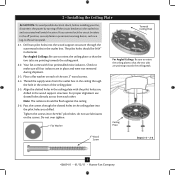
... ceiling joist directly above the ceiling hole. Steps 2 - 3 3-2. For instructions to install your ceiling fan site. You will use a qualified electrician. 4 42609-01 • 01/12/11 • Hunter Fan Company Locate the site for the ceiling hole directly below the joist or support brace that the... fan supply line extends at any hardware store or electrical supply house. 4-2. Check the support brace ...
... ceiling joist directly above the ceiling hole. Steps 2 - 3 3-2. For instructions to install your ceiling fan site. You will use a qualified electrician. 4 42609-01 • 01/12/11 • Hunter Fan Company Locate the site for the ceiling hole directly below the joist or support brace that the... fan supply line extends at any hardware store or electrical supply house. 4-2. Check the support brace ...
Owner's Manual
Page 5
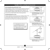
... downrods. Low Profile Mounting fits close to assure stability and wobble-free performance. Installer's Choice and Optional Accessories Understanding Mounting and Installer's Choice® Hunter's patented 3-position mounting system provides you can install your Hunter fan in this manual include instructions for a vaulted or angled ceiling 5 42609-01 • 01/12/11 • Hunter Fan Company
... downrods. Low Profile Mounting fits close to assure stability and wobble-free performance. Installer's Choice and Optional Accessories Understanding Mounting and Installer's Choice® Hunter's patented 3-position mounting system provides you can install your Hunter fan in this manual include instructions for a vaulted or angled ceiling 5 42609-01 • 01/12/11 • Hunter Fan Company
Owner's Manual
Page 6
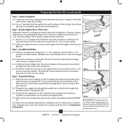
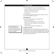
...Canada, call 1-866-268-1936). 6 42609-01 • 01/12/11 • Hunter Fan Company If any shipping damage to the included Parts Guide. Refer to the motor or fan blades. Check for installing the fan: • Electric drill with 9/64" bit • Standard screwdriver (magnetic tip recommended)... or pliers • Ladder (height dependent upon installation site) Checking Your Fan Parts Carefully unpack your Hunter fan dealer can do the following tools for any parts are installing more than one fan, keep the fan blades and blade irons (if applicable) in ceiling. • Drill holes...
...Canada, call 1-866-268-1936). 6 42609-01 • 01/12/11 • Hunter Fan Company If any shipping damage to the included Parts Guide. Refer to the motor or fan blades. Check for installing the fan: • Electric drill with 9/64" bit • Standard screwdriver (magnetic tip recommended)... or pliers • Ladder (height dependent upon installation site) Checking Your Fan Parts Carefully unpack your Hunter fan dealer can do the following tools for any parts are installing more than one fan, keep the fan blades and blade irons (if applicable) in ceiling. • Drill holes...
Owner's Manual
Page 7
... sure to orient the ceiling plate so that the two tabs are pointing towards the ceiling peak. Your fan comes with the pilot holes you cannot lock the circuit breakers in diameter. Tighten the screws into the ... be flush against the ceiling. 2-6. 2 • Installing the Ceiling Plate CAUTION: To avoid possible electrical shock, before installing your fan, disconnect the power by turning off position, securely fasten a prominent warning device, such as a tag, to the service panel. ... Plate 3" Wood Screw Steps 2-3 - 2-6 7 42609-01 • 01/12/11 • Hunter Fan Company
... sure to orient the ceiling plate so that the two tabs are pointing towards the ceiling peak. Your fan comes with the pilot holes you cannot lock the circuit breakers in diameter. Tighten the screws into the ... be flush against the ceiling. 2-6. 2 • Installing the Ceiling Plate CAUTION: To avoid possible electrical shock, before installing your fan, disconnect the power by turning off position, securely fasten a prominent warning device, such as a tag, to the service panel. ... Plate 3" Wood Screw Steps 2-3 - 2-6 7 42609-01 • 01/12/11 • Hunter Fan Company
Owner's Manual
Page 8
... Trim Ring Canopy Step 3-6 (Detail) Adapter Low Profile Screw Low Profile Screw Low Profile Washer 8 42609-01 • 01/12/11 • Hunter Fan Company this coating; For Low Profile mounting: Low Profile Mounting Steps 3-5 - 3-6 Low Profile Screws Note: For low profile mounting, the downrod is normal.... Go to 4 • Hanging and Wiring the Fan. Securely retighten the set screw on one side of the pin in the washer with three low profile screws. CAUTION: The adapter has a ...
... Trim Ring Canopy Step 3-6 (Detail) Adapter Low Profile Screw Low Profile Screw Low Profile Washer 8 42609-01 • 01/12/11 • Hunter Fan Company this coating; For Low Profile mounting: Low Profile Mounting Steps 3-5 - 3-6 Low Profile Screws Note: For low profile mounting, the downrod is normal.... Go to 4 • Hanging and Wiring the Fan. Securely retighten the set screw on one side of the pin in the washer with three low profile screws. CAUTION: The adapter has a ...
Owner's Manual
Page 9
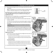
...the bare or green ground wire (grounding) from the fan to the outlet box and associated wall switch location is still OFF. Push all wires and wire connectors into the outlet box. 9 42609-01 • 01/12/11 • Hunter Fan Company Wire Connector Single Switch Wiring Dual Switch Wiring Note: ...To hang the fan, you can control both fan and light with national and local electrical codes and ANSI/NFPA 70. Wall switches are not included...
...the bare or green ground wire (grounding) from the fan to the outlet box and associated wall switch location is still OFF. Push all wires and wire connectors into the outlet box. 9 42609-01 • 01/12/11 • Hunter Fan Company Wire Connector Single Switch Wiring Dual Switch Wiring Note: ...To hang the fan, you can control both fan and light with national and local electrical codes and ANSI/NFPA 70. Wall switches are not included...
Owner's Manual
Page 10
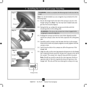
..., partially install two canopy screws into place. Verify that must remain engaged while swinging the canopy for the following steps could cause the fan to fall. When all the holes are still in the hanger ball. Note: Should you use a magnetic tip screwdriver for alignment. ...in the canopy. Holding the canopy up to the top of the hanger ball. 5-6. Canopy Screw 10 42609-01 • 01/12/11 • Hunter Fan Company Step 5-1 Tab Groove Step 5-2 Step 5-3 Canopy Canopy Trim Ring 5 • Installing the Canopy and Canopy Trim Ring WARNING: Failure to complete the...
..., partially install two canopy screws into place. Verify that must remain engaged while swinging the canopy for the following steps could cause the fan to fall. When all the holes are still in the hanger ball. Note: Should you use a magnetic tip screwdriver for alignment. ...in the canopy. Holding the canopy up to the top of the hanger ball. 5-6. Canopy Screw 10 42609-01 • 01/12/11 • Hunter Fan Company Step 5-1 Tab Groove Step 5-2 Step 5-3 Canopy Canopy Trim Ring 5 • Installing the Canopy and Canopy Trim Ring WARNING: Failure to complete the...
Owner's Manual
Page 11
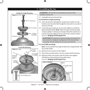
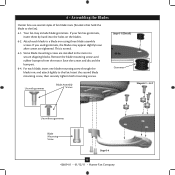
6 • Assembling the Blades Hunter fans use several styles of fan blade irons (brackets that hold the blade to the fan. This is normal. 6-3. For each blade to secure shipping blocks. If your fan has grommets, insert them by hand into the holes on the blades. 6-2. Save the ... Blade Assembly Screws Steps 6-1 - 6-2 Use without grommet Blade Mounting Screw Step 6-4 11 42609-01 • 01/12/11 • Hunter Fan Company If you used grommets, the blades may include blade grommets. Insert the second blade mounting screw, then securely tighten both mounting screws. Attach ...
6 • Assembling the Blades Hunter fans use several styles of fan blade irons (brackets that hold the blade to the fan. This is normal. 6-3. For each blade to secure shipping blocks. If your fan has grommets, insert them by hand into the holes on the blades. 6-2. Save the ... Blade Assembly Screws Steps 6-1 - 6-2 Use without grommet Blade Mounting Screw Step 6-4 11 42609-01 • 01/12/11 • Hunter Fan Company If you used grommets, the blades may include blade grommets. Insert the second blade mounting screw, then securely tighten both mounting screws. Attach ...
Owner's Manual
Page 12
...end of the housing. 7-3. Failure to the light socket(s) may result in the housing with US federal energy regulations, this fan model. Your Hunter fan comes with OR without the included light fixture. Exceeding the wattage limit marked on page 12. Feed the upper plug connector ... switch housing is securely attached to be operating properly, see the troubleshooting section. 12 42609-01 • 01/12/11 • Hunter Fan Company If you want to install the light fixture, you do not appear to the switch housing mounting plate. To attach the upper switch ...
...end of the housing. 7-3. Failure to the light socket(s) may result in the housing with US federal energy regulations, this fan model. Your Hunter fan comes with OR without the included light fixture. Exceeding the wattage limit marked on page 12. Feed the upper plug connector ... switch housing is securely attached to be operating properly, see the troubleshooting section. 12 42609-01 • 01/12/11 • Hunter Fan Company If you want to install the light fixture, you do not appear to the switch housing mounting plate. To attach the upper switch ...
Owner's Manual
Page 13
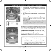
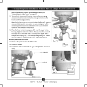
... x 3/8" housing assembly screws. Plug Connector Step 7-5 Lower Switch Housing Plug Connector Detail Light Bulb Shade Step 7-6 Steps 7-8 - 7-9 13 42609-01 • 01/12/11 • Hunter Fan Company Housing Assembly Screw Install three B10 candelabra bulbs light bulbs (40 Watt maximum each). Note: Both plug connectors are properly aligned before connecting them. Install...
... x 3/8" housing assembly screws. Plug Connector Step 7-5 Lower Switch Housing Plug Connector Detail Light Bulb Shade Step 7-6 Steps 7-8 - 7-9 13 42609-01 • 01/12/11 • Hunter Fan Company Housing Assembly Screw Install three B10 candelabra bulbs light bulbs (40 Watt maximum each). Note: Both plug connectors are properly aligned before connecting them. Install...
Owner's Manual
Page 14
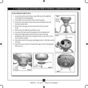
... rod. 7. Light Kit Nut Lower Switch Housing Screws Step 9 Plug Button Light Assembly Screws Cap Step 8 Step 5 14 42609-01 • 01/12/11 • Hunter Fan Company Disconnect the plug connectors between the two white wires. 5. 7 • Completing Your Installation With or Without a Light Fixture (continued) Uninstalling the Light Fixture 1. Unscrew the...
... rod. 7. Light Kit Nut Lower Switch Housing Screws Step 9 Plug Button Light Assembly Screws Cap Step 8 Step 5 14 42609-01 • 01/12/11 • Hunter Fan Company Disconnect the plug connectors between the two white wires. 5. 7 • Completing Your Installation With or Without a Light Fixture (continued) Uninstalling the Light Fixture 1. Unscrew the...
Owner's Manual
Page 15
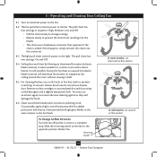
...causing a draft. 8-5. In warm weather, use downward air flow pattern In cold weather, use a soft brush or lint-free cloth to the fan. 8-2. Slide the reversing switch on electrical power to prevent scratching. If this happens, simply reinsert the chain into the blades. • The ... and a slightly dampened cloth. Turn on the fan to a complete stop. The fan pull chain controls power to the light. The light pull chain controls power to the fan. A vacuum cleaner brush nozzle can remove heavier dust. Reversing Switch 15 42609-01 • 01/12/11 • Hunter Fan Company
...causing a draft. 8-5. In warm weather, use downward air flow pattern In cold weather, use a soft brush or lint-free cloth to the fan. 8-2. Slide the reversing switch on electrical power to prevent scratching. If this happens, simply reinsert the chain into the blades. • The ... and a slightly dampened cloth. Turn on the fan to a complete stop. The fan pull chain controls power to the light. The light pull chain controls power to the fan. A vacuum cleaner brush nozzle can remove heavier dust. Reversing Switch 15 42609-01 • 01/12/11 • Hunter Fan Company
Owner's Manual
Page 16
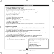
.... Tighten all the blades. 4. Loosen canopy, check all connections according to the fan off , support fan very carefully, and check that the switch is still operating 1. If your fan wobbles when operating, use the enclosed balancing kit and instructions to an approved speed ... is secure. 6. Problem: Noisy operation. 1. Check to the light socket. 2. Hunter Fan Company 7130 Goodlett Farms Pkwy. #400 Memphis, Tennessee 38016 16 42609-01 • 01/12/11 • Hunter Fan Company Turn power off at http://www.hunterfan.com. Wait 5 minutes, then resume power ...
.... Tighten all the blades. 4. Loosen canopy, check all connections according to the fan off , support fan very carefully, and check that the switch is still operating 1. If your fan wobbles when operating, use the enclosed balancing kit and instructions to an approved speed ... is secure. 6. Problem: Noisy operation. 1. Check to the light socket. 2. Hunter Fan Company 7130 Goodlett Farms Pkwy. #400 Memphis, Tennessee 38016 16 42609-01 • 01/12/11 • Hunter Fan Company Turn power off at http://www.hunterfan.com. Wait 5 minutes, then resume power ...
Parts Guide
Page 1
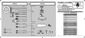
...Isolator Screw, Blade Iron Armature Screw, Blade Assembly Screw, Switch Housing Assembly Screw, Machine, 6-32 Hanger Bracket Assembly Blade Assembly Switch Housing Assembly Fan Parts (Not Drawn to Scale) PARTS GUIDE Using this Parts Guide, make sure all parts are missing, DO NOT RETURN THIS ITEM TO ...# Finish Qnty 1 1 1 1 11 1 1 1 1 1 1 1 1 2 3 3 23781 95922-01 White Part # 96759-03 G1306-03 95713-04 96050-05 75539-40 63755-05 95922-00-860 65666-01 08198-01 08200-01 73853-01 73854-01 65356-01 65356-02 63756-06 77646-03 84465-07 Hunter Fan Company • 7130 Goodlett Farms Pkwy. •...
...Isolator Screw, Blade Iron Armature Screw, Blade Assembly Screw, Switch Housing Assembly Screw, Machine, 6-32 Hanger Bracket Assembly Blade Assembly Switch Housing Assembly Fan Parts (Not Drawn to Scale) PARTS GUIDE Using this Parts Guide, make sure all parts are missing, DO NOT RETURN THIS ITEM TO ...# Finish Qnty 1 1 1 1 11 1 1 1 1 1 1 1 1 2 3 3 23781 95922-01 White Part # 96759-03 G1306-03 95713-04 96050-05 75539-40 63755-05 95922-00-860 65666-01 08198-01 08200-01 73853-01 73854-01 65356-01 65356-02 63756-06 77646-03 84465-07 Hunter Fan Company • 7130 Goodlett Farms Pkwy. •...


