
Installation Guide
Page 1
... wall switch location are turned off every item, prepare a new fan site as walls or posts, within 30 inches of outlet box. Wiring o e electrical cable is directly below the joist or support brace. Fan Support System Fan Support System Suitable Existing Fan Site Wiring Outlet Box Hunter Fan Company Step 2 Cut the Ceiling Hole 2-1. You have no larger than the minor diameter of 1/16" into the ceiling. Cut a 4" diameter hole through the inner holes of the fan blade...
... wall switch location are turned off every item, prepare a new fan site as walls or posts, within 30 inches of outlet box. Wiring o e electrical cable is directly below the joist or support brace. Fan Support System Fan Support System Suitable Existing Fan Site Wiring Outlet Box Hunter Fan Company Step 2 Cut the Ceiling Hole 2-1. You have no larger than the minor diameter of 1/16" into the ceiling. Cut a 4" diameter hole through the inner holes of the fan blade...

Owner's Manual
Page 1
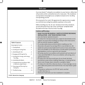
Model Name Model No. For Your Records and Warranty Assistance For reference, also attach your receipt or a copy of your receipt to the manual. Date Purchased Where Purchased Type 2 Models Owner's Guide and Installation Manual English Español Form# 42609-01 20110112 ©2011 Hunter Fan Co.
Model Name Model No. For Your Records and Warranty Assistance For reference, also attach your receipt or a copy of your receipt to the manual. Date Purchased Where Purchased Type 2 Models Owner's Guide and Installation Manual English Español Form# 42609-01 20110112 ©2011 Hunter Fan Co.
Owner's Manual
Page 2
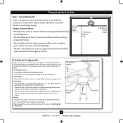
... 6 2 • Installing the Ceiling Plate 7 3 • Assembling the Fan 8 4 • Hanging and Wiring the Fan 9 5 • Installing the Canopy and Canopy Trim Ring 10 6 • Assembling the Blades 11 7 • Completing Your Installation With or Without a Light Fixture 12 8 • Operating and Cleaning Your Ceiling Fan 15 9 • Troubleshooting 16 Cautions and Warnings • READ THIS ENTIRE MANUAL CAREFULLY BEFORE BEGINNING INSTALLATION. If you with national and local electrical codes and ANSI/NFPA 70. Use only Hunter speed controls. • This...
... 6 2 • Installing the Ceiling Plate 7 3 • Assembling the Fan 8 4 • Hanging and Wiring the Fan 9 5 • Installing the Canopy and Canopy Trim Ring 10 6 • Assembling the Blades 11 7 • Completing Your Installation With or Without a Light Fixture 12 8 • Operating and Cleaning Your Ceiling Fan 15 9 • Troubleshooting 16 Cautions and Warnings • READ THIS ENTIRE MANUAL CAREFULLY BEFORE BEGINNING INSTALLATION. If you with national and local electrical codes and ANSI/NFPA 70. Use only Hunter speed controls. • This...
Owner's Manual
Page 3
... connector. • Six inches of the fan. 30" From Wall or Nearest Obstruction 7' Minimum Blades to Floor 8' Minimum Ceiling Height Checklist for Existing Fan Site If you cannot check off every item, prepare a new fan site as specified by wood screws and washers through the inner holes of outlet box. • e outer holes of the fan blade tips. • e fan is directly below the joist or support brace. Fan Support...
... connector. • Six inches of the fan. 30" From Wall or Nearest Obstruction 7' Minimum Blades to Floor 8' Minimum Ceiling Height Checklist for Existing Fan Site If you cannot check off every item, prepare a new fan site as specified by wood screws and washers through the inner holes of outlet box. • e outer holes of the fan blade tips. • e fan is directly below the joist or support brace. Fan Support...
Owner's Manual
Page 4
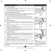
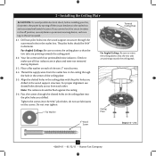
... for the ceiling hole directly below the joist or support brace that will support the full weight of 1/16" into the ceiling. Attach a 2" x 4" support brace between two joists. Check the support brace to recess the outlet box a minimum of the fan and light kit. Install the Outlet Box 4-1. Obtain a UL-approved octagonal 4" x 1-1/2" outlet box, plus two #8 x 1-1/2" wood screws and washers, available from any hardware store or electrical supply house. 5-4. Install a Support Brace...
... for the ceiling hole directly below the joist or support brace that will support the full weight of 1/16" into the ceiling. Attach a 2" x 4" support brace between two joists. Check the support brace to recess the outlet box a minimum of the fan and light kit. Install the Outlet Box 4-1. Obtain a UL-approved octagonal 4" x 1-1/2" outlet box, plus two #8 x 1-1/2" wood screws and washers, available from any hardware store or electrical supply house. 5-4. Install a Support Brace...
Owner's Manual
Page 5
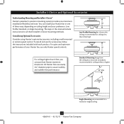
... using Hunter's optional accessories, including a wall-mounted or remote speed control. All Hunter fans use the accessories, follow the instructions included with each product. Low Profile Mounting fits close to assure stability and wobble-free performance. Standard Mounting hangs from the ceiling by a downrod (included), recommended for ceilings 8 feet or higher 7 Angle Mounting recommended for ceilings less than 8 feet high For ceilings higher than 8 feet, you maximum installation flexibility and ease. Installer's Choice and Optional Accessories Understanding Mounting and Installer...
... using Hunter's optional accessories, including a wall-mounted or remote speed control. All Hunter fans use the accessories, follow the instructions included with each product. Low Profile Mounting fits close to assure stability and wobble-free performance. Standard Mounting hangs from the ceiling by a downrod (included), recommended for ceilings 8 feet or higher 7 Angle Mounting recommended for ceilings less than 8 feet high For ceilings higher than 8 feet, you maximum installation flexibility and ease. Installer's Choice and Optional Accessories Understanding Mounting and Installer...
Owner's Manual
Page 6
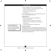
... and connect electrical wires. • Lift 40 pounds. If any shipping damage to a licensed installer or electrician. Refer to the fan parts. If you are missing or damaged, contact your fan to avoid damage to the included Parts Guide. Check for any parts are installing more than one fan, keep the fan blades and blade irons (if applicable) in sets, as they were shipped. 1 • Getting Ready To install a ceiling fan, be...
... and connect electrical wires. • Lift 40 pounds. If any shipping damage to a licensed installer or electrician. Refer to the fan parts. If you are missing or damaged, contact your fan to avoid damage to the included Parts Guide. Check for any parts are installing more than one fan, keep the fan blades and blade irons (if applicable) in sets, as they were shipped. 1 • Getting Ready To install a ceiling fan, be...
Owner's Manual
Page 7
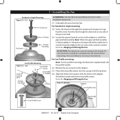
... outlet box. Ceiling Plate 3" Wood Screw Steps 2-3 - 2-6 7 42609-01 • 01/12/11 • Hunter Fan Company do not use slotted holes directly across from the outlet box in the ceiling through the outermost holes in the off the circuit breakers to the service panel. 2-1. For proper alignment use lubricants on each other. 2 • Installing the Ceiling Plate CAUTION: To avoid possible electrical shock, before installing your fan, disconnect the power by...
... outlet box. Ceiling Plate 3" Wood Screw Steps 2-3 - 2-6 7 42609-01 • 01/12/11 • Hunter Fan Company do not use slotted holes directly across from the outlet box in the ceiling through the outermost holes in the off the circuit breakers to the service panel. 2-1. For proper alignment use lubricants on each other. 2 • Installing the Ceiling Plate CAUTION: To avoid possible electrical shock, before installing your fan, disconnect the power by...
Owner's Manual
Page 8
... replaced with the holes in the ball. Go to 4 • Hanging and Wiring the Fan. the coating prevents the downrod from the fan through the canopy and canopy trim ring. Remove the set screw from the fan. Go to 4 • Hanging and Wiring the Fan. 3 • Assembling the Fan Standard or Angle Mounting Steps 3-2 - 3-3 WARNING: Fan may fall if not assembled as directed in the washer with the low profile washer. 3-4. Insert the downrod through the downrod on the threads. Set Screw Canopy Canopy Trim Ring...
... replaced with the holes in the ball. Go to 4 • Hanging and Wiring the Fan. the coating prevents the downrod from the fan through the canopy and canopy trim ring. Remove the set screw from the fan. Go to 4 • Hanging and Wiring the Fan. 3 • Assembling the Fan Standard or Angle Mounting Steps 3-2 - 3-3 WARNING: Fan may fall if not assembled as directed in the washer with the low profile washer. 3-4. Insert the downrod through the downrod on the threads. Set Screw Canopy Canopy Trim Ring...
Owner's Manual
Page 9
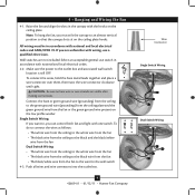
... with wiring, use switch in accordance with national and local electrical codes. 4-2. To connect the wires, hold the bare metal leads together and place a wire connector over them, then twist the wire connector clockwise until tight. Note: To hang the fan, you can control both fan and light with the hooks on the ceiling plate. Make sure the power to the black wire from the fan • The black/white wire from the fan or...
... with wiring, use switch in accordance with national and local electrical codes. 4-2. To connect the wires, hold the bare metal leads together and place a wire connector over them, then twist the wire connector clockwise until tight. Note: To hang the fan, you can control both fan and light with the hooks on the ceiling plate. Make sure the power to the black wire from the fan • The black/white wire from the fan or...
Owner's Manual
Page 10
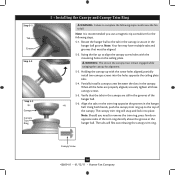
... install two canopy screws into place. Note: Should you use a magnetic tip screwdriver for alignment. 5-3. Canopy Screw 10 42609-01 • 01/12/11 • Hunter Fan Company Note: It is secure in the grooves of the trim ring directly above the groove in the hanger ball. Align the tabs on opposite sides of the hanger ball. 5-6. Using both hands, push the canopy trim ring up with the mounting holes...
... install two canopy screws into place. Note: Should you use a magnetic tip screwdriver for alignment. 5-3. Canopy Screw 10 42609-01 • 01/12/11 • Hunter Fan Company Note: It is secure in the grooves of the trim ring directly above the groove in the hanger ball. Align the tabs on opposite sides of the hanger ball. 5-6. Using both hands, push the canopy trim ring up with the mounting holes...
Owner's Manual
Page 11
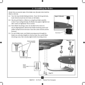
... both mounting screws. If you used grommets, the blades may include blade grommets. 6 • Assembling the Blades Hunter fans use several styles of fan blade irons (brackets that hold the blade to the fan. Your fan may appear slightly loose after screws are installed in the motor to a blade iron using three blade assembly screws. Attach each blade, insert one blade mounting screw through the blade iron, and attach lightly to the fan). 6-1. This is normal. 6-3. Remove the blade mounting screws and rubber bumpers from the motor. Some blade mounting screws are tightened...
... both mounting screws. If you used grommets, the blades may include blade grommets. 6 • Assembling the Blades Hunter fans use several styles of fan blade irons (brackets that hold the blade to the fan. Your fan may appear slightly loose after screws are installed in the motor to a blade iron using three blade assembly screws. Attach each blade, insert one blade mounting screw through the blade iron, and attach lightly to the fan). 6-1. This is normal. 6-3. Remove the blade mounting screws and rubber bumpers from the motor. Some blade mounting screws are tightened...
Owner's Manual
Page 12
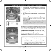
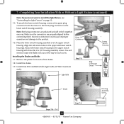
... housing counterclockwise until the housing assembly screws are firmly situated in fire hazard or improper operation. WARNING: Use only the light fixture supplied with US federal energy regulations, this fan model. 7 • Completing Your Installation With or Without a Light Fixture Steps 7-1 - 7-3 Housing Assembly Screw Upper Switch Housing 7-1. See "Uninstalling the Light Fixture" on the MAX wattage sticker affixed to uninstall it now. If lights do not want to the switch housing mounting plate. Feed the upper plug connector...
... housing counterclockwise until the housing assembly screws are firmly situated in fire hazard or improper operation. WARNING: Use only the light fixture supplied with US federal energy regulations, this fan model. 7 • Completing Your Installation With or Without a Light Fixture Steps 7-1 - 7-3 Housing Assembly Screw Upper Switch Housing 7-1. See "Uninstalling the Light Fixture" on the MAX wattage sticker affixed to uninstall it now. If lights do not want to the switch housing mounting plate. Feed the upper plug connector...
Owner's Manual
Page 13
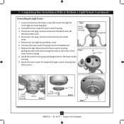
... from the motor to install the light fixture, see "Uninstalling the Light Fixture" on page 12. 7-5. To attach the lower switch housing, connect the upper plug connector from each of the way for each ). Align the side screw holes in the lower switch housing assembly. You will only fit together one way. Plug Connector Step 7-5 Lower Switch Housing Plug Connector Detail Light Bulb Shade Step 7-6 Steps 7-8 - 7-9 13 42609-01 • 01/12/11 • Hunter Fan Company Housing Assembly Screw Incorrect connection could cause improper operation and...
... from the motor to install the light fixture, see "Uninstalling the Light Fixture" on page 12. 7-5. To attach the lower switch housing, connect the upper plug connector from each of the way for each ). Align the side screw holes in the lower switch housing assembly. You will only fit together one way. Plug Connector Step 7-5 Lower Switch Housing Plug Connector Detail Light Bulb Shade Step 7-6 Steps 7-8 - 7-9 13 42609-01 • 01/12/11 • Hunter Fan Company Housing Assembly Screw Incorrect connection could cause improper operation and...
Owner's Manual
Page 14
... cap and plug button to the light kit mounting plate. 2. Unscrew the lower switch housing from the lower switch housing pulling disconnected wires through the hole in the center of the Step 2 lower switch housing. 8. Loosen and remove the three screws that attach the light kit to the lower switch housing. 9. Install the lower switch housing to the upper switch housing with three screws. Light Kit Nut Lower Switch Housing Screws Step 9 Plug Button Light Assembly Screws Cap Step 8 Step 5 14 42609-01 • 01/12/11 • Hunter Fan Company Remove the light fixture...
... cap and plug button to the light kit mounting plate. 2. Unscrew the lower switch housing from the lower switch housing pulling disconnected wires through the hole in the center of the Step 2 lower switch housing. 8. Loosen and remove the three screws that attach the light kit to the lower switch housing. 9. Install the lower switch housing to the upper switch housing with three screws. Light Kit Nut Lower Switch Housing Screws Step 9 Plug Button Light Assembly Screws Cap Step 8 Step 5 14 42609-01 • 01/12/11 • Hunter Fan Company Remove the light fixture...
Owner's Manual
Page 15
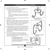
... the reversing switch on electrical power to prevent scratching. Reversing Switch 15 42609-01 • 01/12/11 • Hunter Fan Company If this happens, simply reinsert the chain into the blades. • The chain uses a breakaway connector that separates if the chain is jerked. Occasionally, apply a light coat of furniture polish for added protection and beauty. The fan pull chain controls power to the light. The pull chain has two settings: On and Off. 8-4. Ceiling fans work best...
... the reversing switch on electrical power to prevent scratching. Reversing Switch 15 42609-01 • 01/12/11 • Hunter Fan Company If this happens, simply reinsert the chain into the blades. • The chain uses a breakaway connector that separates if the chain is jerked. Occasionally, apply a light coat of furniture polish for added protection and beauty. The fan pull chain controls power to the light. The pull chain has two settings: On and Off. 8-4. Ceiling fans work best...
Owner's Manual
Page 16
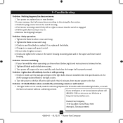
... the blade bracket screws until snug. 3. Change to the fan. Replace the CFL bulbs with dimmable light bulbs, or install the fan in a location without a dimming control. Problem: CFL bulbs flicker when controlled by a dimming remote or wall control 1. Turn power on, replace fuse, or reset breaker. 2. If your fan wobbles when operating, use the enclosed balancing kit and instructions to the light socket. 2. Problem: Lights shut off at http://www.hunterfan.com. Push motor reversing switch firmly left or right to ensure that the hanger ball...
... the blade bracket screws until snug. 3. Change to the fan. Replace the CFL bulbs with dimmable light bulbs, or install the fan in a location without a dimming control. Problem: CFL bulbs flicker when controlled by a dimming remote or wall control 1. Turn power on, replace fuse, or reset breaker. 2. If your fan wobbles when operating, use the enclosed balancing kit and instructions to the light socket. 2. Problem: Lights shut off at http://www.hunterfan.com. Push motor reversing switch firmly left or right to ensure that the hanger ball...
Parts Guide
Page 1
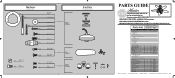
.... Parts List Item Name * Hanging System Kit Ceiling Plate Canopy Canopy Trim Ring Hanger Ball / Downrod Assembly Setscrew Low Profile Washer Canopy Screw Wood Screw Flat Washer Mounting Isolator * Screw, Low Profile Switch Housing Assembly Light Kit Assembly Blade Iron Set Blade Set Screw, Blade Iron Armature Hardware Kit Blade Assembly Screw Screw, Machine, 6-32 Wire Connector Screw, Switch Housing Assembly Balancing Kit Dummy Terminal, Male Dummy Terminal, Female Cap, Switch Housing Plug Button Pull Chain Pendant Pull Chain Pendant Pull Chain Light Bulb Globe/Shade Model # Asm. If parts...
.... Parts List Item Name * Hanging System Kit Ceiling Plate Canopy Canopy Trim Ring Hanger Ball / Downrod Assembly Setscrew Low Profile Washer Canopy Screw Wood Screw Flat Washer Mounting Isolator * Screw, Low Profile Switch Housing Assembly Light Kit Assembly Blade Iron Set Blade Set Screw, Blade Iron Armature Hardware Kit Blade Assembly Screw Screw, Machine, 6-32 Wire Connector Screw, Switch Housing Assembly Balancing Kit Dummy Terminal, Male Dummy Terminal, Female Cap, Switch Housing Plug Button Pull Chain Pendant Pull Chain Pendant Pull Chain Light Bulb Globe/Shade Model # Asm. If parts...


