
Installation Guide
Page 1
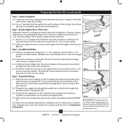
...if it to allow you cannot check off . o Six inches of 1/16" into the ceiling. 3-2. Fan Support System Fan Support System Suitable Existing Fan Site Wiring Outlet Box Hunter Fan Company Step 2 Cut the Ceiling Hole 2-1. Make certain the wiring meets all national and local standards and ... any hardware store or electrical supply house. 4-2. If you to recess the outlet box a minimum of the fan blade tips. • e fan is suitable, go to your fan manual and continue with the joist or support brace. 4-3. If NOT, install a support brace as follows: 3-1. ...
...if it to allow you cannot check off . o Six inches of 1/16" into the ceiling. 3-2. Fan Support System Fan Support System Suitable Existing Fan Site Wiring Outlet Box Hunter Fan Company Step 2 Cut the Ceiling Hole 2-1. Make certain the wiring meets all national and local standards and ... any hardware store or electrical supply house. 4-2. If you to recess the outlet box a minimum of the fan blade tips. • e fan is suitable, go to your fan manual and continue with the joist or support brace. 4-3. If NOT, install a support brace as follows: 3-1. ...

Owner's Manual
Page 1
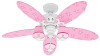
Model Name Model No. Date Purchased Where Purchased Type 2 Models Owner's Guide and Installation Manual English Español Form# 42609-01 20110112 ©2011 Hunter Fan Co. For Your Records and Warranty Assistance For reference, also attach your receipt or a copy of your receipt to the manual.
Model Name Model No. Date Purchased Where Purchased Type 2 Models Owner's Guide and Installation Manual English Español Form# 42609-01 20110112 ©2011 Hunter Fan Co. For Your Records and Warranty Assistance For reference, also attach your receipt or a copy of your receipt to the manual.
Owner's Manual
Page 2
... the circuit breakers to your records and warranty assistance, record information from the carton and Hunter nameplate label (located on the top of our work. If you with this fan. If you complete instructions for many years. We are unfamiliar with wiring, use a ... hands after your fan installation is an addition to the outlet box and associated wall switch location. Welcome Your new Hunter® ceiling fan is complete. © 2011 Hunter Fan Company 2 42609-01 • 01/12/11 • Hunter Fan Company This installation and operation manual gives you are proud...
... the circuit breakers to your records and warranty assistance, record information from the carton and Hunter nameplate label (located on the top of our work. If you with this fan. If you complete instructions for many years. We are unfamiliar with wiring, use a ... hands after your fan installation is an addition to the outlet box and associated wall switch location. Welcome Your new Hunter® ceiling fan is complete. © 2011 Hunter Fan Company 2 42609-01 • 01/12/11 • Hunter Fan Company This installation and operation manual gives you are proud...
Owner's Manual
Page 4
...outlet box with national and local electrical codes and ANSI/NFPA 70. You have now successfully prepared your fan manual and continue with wiring, use a qualified electrician. 4 42609-01 • 01/12/11 • Hunter Fan Company Steps 2 - 3 3-2. Prepare the Wiring 5-1. Position it to allow you cannot lock the ... be recessed a minimum of 1/16" into the ceiling. Orient the outlet box so that will use the hole to the fan supply line leads and associated wall switch location are unfamiliar with Section 2 • Installing the Ceiling Plate. If you to your ceiling...
...outlet box with national and local electrical codes and ANSI/NFPA 70. You have now successfully prepared your fan manual and continue with wiring, use a qualified electrician. 4 42609-01 • 01/12/11 • Hunter Fan Company Steps 2 - 3 3-2. Prepare the Wiring 5-1. Position it to allow you cannot lock the ... be recessed a minimum of 1/16" into the ceiling. Orient the outlet box so that will use the hole to the fan supply line leads and associated wall switch location are unfamiliar with Section 2 • Installing the Ceiling Plate. If you to your ceiling...
Owner's Manual
Page 5
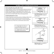
...-free performance. For quiet and optimum performance of three ways, depending on ceiling height and your Hunter fan, use only Hunter speed controls. You can purchase Hunter extension downrods. The steps in one of your preference: Low Profile, Standard, or Angle mounting.... Installer's Choice and Optional Accessories Understanding Mounting and Installer's Choice® Hunter's patented 3-position mounting system provides you can install your Hunter fan in this manual include instructions for a vaulted or angled ceiling 5 42609-01 • 01/12/11 •...
...-free performance. For quiet and optimum performance of three ways, depending on ceiling height and your Hunter fan, use only Hunter speed controls. You can purchase Hunter extension downrods. The steps in one of your preference: Low Profile, Standard, or Angle mounting.... Installer's Choice and Optional Accessories Understanding Mounting and Installer's Choice® Hunter's patented 3-position mounting system provides you can install your Hunter fan in this manual include instructions for a vaulted or angled ceiling 5 42609-01 • 01/12/11 •...
Parts Guide
Page 1
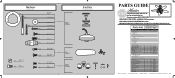
...1 1 1 1 1 1 1 2 3 3 23781 95922-01 White Part # 96759-03 G1306-03 95713-04 96050-05 75539-40 63755-05 95922-00-860 65666-01 08198-01 08200-01 73853-01 73854-01 65356-01 65356-02 63756-06 77646-03 84465-07 Hunter Fan Company • 7130 Goodlett Farms Pkwy. • Memphis... Pull Chain Pendant Pull Chain Pendant Pull Chain Light Bulb Globe/Shade Model # Asm. THIS PARTS GUIDE IS FOR REFERENCE ONLY. REFER TO THE INSTALLATION MANUAL FOR FULL ASSEMBLY INSTRUCTIONS. Hardware (Drawn to Scale) x 1 x 2 x 4 x 2 x 3 x 4 x 1 x 4 x 11 Balancing x 1 Kit Wire x 4 Connector x 16 x 3 x 3 Low ...
...1 1 1 1 1 1 1 2 3 3 23781 95922-01 White Part # 96759-03 G1306-03 95713-04 96050-05 75539-40 63755-05 95922-00-860 65666-01 08198-01 08200-01 73853-01 73854-01 65356-01 65356-02 63756-06 77646-03 84465-07 Hunter Fan Company • 7130 Goodlett Farms Pkwy. • Memphis... Pull Chain Pendant Pull Chain Pendant Pull Chain Light Bulb Globe/Shade Model # Asm. THIS PARTS GUIDE IS FOR REFERENCE ONLY. REFER TO THE INSTALLATION MANUAL FOR FULL ASSEMBLY INSTRUCTIONS. Hardware (Drawn to Scale) x 1 x 2 x 4 x 2 x 3 x 4 x 1 x 4 x 11 Balancing x 1 Kit Wire x 4 Connector x 16 x 3 x 3 Low ...


