
Service Manual
Page 1
... HITACHI CM800U,CM801U SERVICE MANUAL I CM802U,CM803U C97(B) Chassis (V1.0) ,--.. HIGH RESOLUTION COLOR DISPLAY MONITOR (AUGUST 1996) CONTENTS FEATURES 2 SAFETY PRECATIONS 2 CHECK OF HIGH VOLTAGE HOLD DOWN CIRCUIT 2 PRODUCT SAFETY NOTICE 3 SPECIFICATIONS 3 CONTROLS 4 SIGNAL TIMING CHART 5 DISCRIPTION OF CIRCUIT 8 ("1 WIRING DIAGRAM 22 BLOCK DIAGRAM 23 BASIC CIRCUIT DIAGRAM 24 PRINTED WIRING BOARD 27 TROBLESHOOTING 30 ADJUSTMENTS 33 REPLACEMENT PART LIST 38 SPECIFICATIONS AND PARTS ARE SUBJECT TO CHANGE FOR IMPROVEMENT. CAUTION: Before servicing...
... HITACHI CM800U,CM801U SERVICE MANUAL I CM802U,CM803U C97(B) Chassis (V1.0) ,--.. HIGH RESOLUTION COLOR DISPLAY MONITOR (AUGUST 1996) CONTENTS FEATURES 2 SAFETY PRECATIONS 2 CHECK OF HIGH VOLTAGE HOLD DOWN CIRCUIT 2 PRODUCT SAFETY NOTICE 3 SPECIFICATIONS 3 CONTROLS 4 SIGNAL TIMING CHART 5 DISCRIPTION OF CIRCUIT 8 ("1 WIRING DIAGRAM 22 BLOCK DIAGRAM 23 BASIC CIRCUIT DIAGRAM 24 PRINTED WIRING BOARD 27 TROBLESHOOTING 30 ADJUSTMENTS 33 REPLACEMENT PART LIST 38 SPECIFICATIONS AND PARTS ARE SUBJECT TO CHANGE FOR IMPROVEMENT. CAUTION: Before servicing...
Service Manual
Page 2
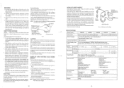
...) To Chassis Ground 0-a=3 -0 O79Z 0-3=0 R792 DEF BOARD ASS'Y Resister 120 kit (1/2W) Fig. 2 Checking Circuit using replacement components rated for continued protection of X-radiation in the high voltage circuitry area. 4 Always use the manufacturer's replacement components. Up to 1024 User Controls Power Switch Degauss Store Contrast Brightness Horizontal Position, Size Vertical Position, Size Right Side Pincushion Right Trapezoid Side Pincushion Trapezoid Parallelogram Red,Green,Blue intensity Color Select Rotation H Moire Reduction V Moire Reduction...
...) To Chassis Ground 0-a=3 -0 O79Z 0-3=0 R792 DEF BOARD ASS'Y Resister 120 kit (1/2W) Fig. 2 Checking Circuit using replacement components rated for continued protection of X-radiation in the high voltage circuitry area. 4 Always use the manufacturer's replacement components. Up to 1024 User Controls Power Switch Degauss Store Contrast Brightness Horizontal Position, Size Vertical Position, Size Right Side Pincushion Right Trapezoid Side Pincushion Trapezoid Parallelogram Red,Green,Blue intensity Color Select Rotation H Moire Reduction V Moire Reduction...
Service Manual
Page 3
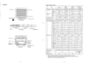
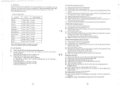
..., Inc.. -5- SIGNAL TIMING CHART Signal VGA 640 X 480 1 Video 2 Sync. Select Switch Adjust Switch 'STORE" 'ADJUSTMENT* "DEGAUSSING" 'POWER ON/OFF' Rear Panel AC Inlet Serial Communication Terminal REAR VIEW 13W3 Type D-Sub Connector Terminal or D-Sub Mini 15-pin Connector Terminal -4- TTL Level (Nega.) TTL Level (Posi.) -71. Type Voltage Set up Type R/G/B Analog 0.7 Vp-p None H/V Separate VESA 800 X 600 (85Hz) R/G/B Analog 0.7 Vp-p None H/V Separate VESA 1024 X 768 (85Hz) R/G/B Analog 0.7 Vp...
..., Inc.. -5- SIGNAL TIMING CHART Signal VGA 640 X 480 1 Video 2 Sync. Select Switch Adjust Switch 'STORE" 'ADJUSTMENT* "DEGAUSSING" 'POWER ON/OFF' Rear Panel AC Inlet Serial Communication Terminal REAR VIEW 13W3 Type D-Sub Connector Terminal or D-Sub Mini 15-pin Connector Terminal -4- TTL Level (Nega.) TTL Level (Posi.) -71. Type Voltage Set up Type R/G/B Analog 0.7 Vp-p None H/V Separate VESA 800 X 600 (85Hz) R/G/B Analog 0.7 Vp-p None H/V Separate VESA 1024 X 768 (85Hz) R/G/B Analog 0.7 Vp...
Service Manual
Page 5
... manual degauss by frequency synchronization with circuit #1, to detect secondary voltage at 19C1 and feed through photocoupler I9A2, providing constant voltage by current flowing through the degauss coil. Power Supply Circuit This model incorporates a wide range universal power supply utilizing a switching regulator (see block diagram in stopping chopper operation at front panel which closes S91R through Q999, to allow current to be turned...
... manual degauss by frequency synchronization with circuit #1, to detect secondary voltage at 19C1 and feed through photocoupler I9A2, providing constant voltage by current flowing through the degauss coil. Power Supply Circuit This model incorporates a wide range universal power supply utilizing a switching regulator (see block diagram in stopping chopper operation at front panel which closes S91R through Q999, to allow current to be turned...

Service Manual
Page 6
... start . The standby power supply also includes a self-excited switching regulator. The main power supply turns on and oscillations start , the switching transistor is applied to OSD Mixer Circuit in which a switching transistor turns on (off voltage is generated at its polarity, Sync signal is applied to 1920 Pin 5. Sync Determination Circuit Depending on the combination of Q9D1 from microprocessor, whose output feeds OSD display signals in R/G/B and OSD...
... start . The standby power supply also includes a self-excited switching regulator. The main power supply turns on and oscillations start , the switching transistor is applied to OSD Mixer Circuit in which a switching transistor turns on (off voltage is generated at its polarity, Sync signal is applied to 1920 Pin 5. Sync Determination Circuit Depending on the combination of Q9D1 from microprocessor, whose output feeds OSD display signals in R/G/B and OSD...

Service Manual
Page 7
... stages of the flyback transformer to 1701 where it with the same design of the horizontal beam current characteristics. The H.sync signal is input to drive the CRT anode. RIG/B Gain control Contrast Control R/G/B Cut control 4. LcLo. The S-consonant capacitors, C771-C779, are changed by the EHv error detection circuit. The power supply paraborically modulates the +B voltage of D752 and D7AZ whose output...
... stages of the flyback transformer to 1701 where it with the same design of the horizontal beam current characteristics. The H.sync signal is input to drive the CRT anode. RIG/B Gain control Contrast Control R/G/B Cut control 4. LcLo. The S-consonant capacitors, C771-C779, are changed by the EHv error detection circuit. The power supply paraborically modulates the +B voltage of D752 and D7AZ whose output...

Service Manual
Page 8
... compensation, horizontal size control, side pin compensation, Right Pin compensation, and vertical linearity compensation. 4.4 Dynamic focus compensation waveform Vertical sync signals are combined with an amplitude proportional to the vertical line frequency, after processing by changing the amplitude of the parabolic waveform. The focus 1 potentiometer mainly adjusts horizontal beam shape (vertical line width), and the focus 2 potentiometer mainly adjusts the vertical beam shape (horizontal line width...
... compensation, horizontal size control, side pin compensation, Right Pin compensation, and vertical linearity compensation. 4.4 Dynamic focus compensation waveform Vertical sync signals are combined with an amplitude proportional to the vertical line frequency, after processing by changing the amplitude of the parabolic waveform. The focus 1 potentiometer mainly adjusts horizontal beam shape (vertical line width), and the focus 2 potentiometer mainly adjusts the vertical beam shape (horizontal line width...

Service Manual
Page 9
STABILIZER R756 Ehv Adj CRT HIGH VOLTAGE MIMI • MIN • FBT HIGH VOLTAGE OUTPUT CIRCUIT HIGH VOLTAGE HOLD-DOWN CIRCUIT DIAGRAM HIGH VOLTAGE OUTPUT CIRCUIT 1701 16 LA78 60 HV DRIVE SIGNAL +12V R745 R742 Q749 D745 Q748 HIGH VOLTAGE +80- When the voltage of D79Z anode which is ...which is determined 8792, R793, R794, D792, Q749 and Q748 are ON, and the HV DRIVE SIGNAL is connected to GND resulted in which an abnormal high voltage is as follows. Chassis uses a system in stopping the HIGH VOLTAGE OUTPUT CIRCUIT and elimination of the circuit operation is detected to ...
STABILIZER R756 Ehv Adj CRT HIGH VOLTAGE MIMI • MIN • FBT HIGH VOLTAGE OUTPUT CIRCUIT HIGH VOLTAGE HOLD-DOWN CIRCUIT DIAGRAM HIGH VOLTAGE OUTPUT CIRCUIT 1701 16 LA78 60 HV DRIVE SIGNAL +12V R745 R742 Q749 D745 Q748 HIGH VOLTAGE +80- When the voltage of D79Z anode which is ...which is determined 8792, R793, R794, D792, Q749 and Q748 are ON, and the HV DRIVE SIGNAL is connected to GND resulted in which an abnormal high voltage is as follows. Chassis uses a system in stopping the HIGH VOLTAGE OUTPUT CIRCUIT and elimination of the circuit operation is detected to ...
Service Manual
Page 10
... adjustment on the screen by stopping main power supply if both H and V sync are not supplied. keys. Position / H. Size (Red adjust), V. O 8 4 m 2 J 7 c4 oa V 41 • N eN (N1 (.O tC) o k-9 o C.3 o o Store key allows current settings (including picture size, geometry, and color setting) to be stored to black level when timing signal changes or the monitor goes into the power saving mode. Data memory consists of H. Osc. control with ROM and RAM for 26 presets including factory standard settings...
... adjustment on the screen by stopping main power supply if both H and V sync are not supplied. keys. Position / H. Size (Red adjust), V. O 8 4 m 2 J 7 c4 oa V 41 • N eN (N1 (.O tC) o k-9 o C.3 o o Store key allows current settings (including picture size, geometry, and color setting) to be stored to black level when timing signal changes or the monitor goes into the power saving mode. Data memory consists of H. Osc. control with ROM and RAM for 26 presets including factory standard settings...

Service Manual
Page 11
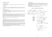
... of the Power save H Sync Yes Sync V Sync Yes No Yes No Yes No No Name VESA Recovery Time Standard Power savings Normal N/A None Standby Short Minimam Suspend Off Short System Dependent Minimam Maximum H. Cap select co (17. a 4-, .-4-, C N 0 I •-32). 2. > .4>t=ao.,). fa))1 L.) I C a w "0 Zn cc 7 r(V)- Deflection Operation Video Power LED Normal operation Normal operation Normal operation Lighting Green Stop Stop Mute Flashing quickly Power consumption All White : 130W...
... of the Power save H Sync Yes Sync V Sync Yes No Yes No Yes No No Name VESA Recovery Time Standard Power savings Normal N/A None Standby Short Minimam Suspend Off Short System Dependent Minimam Maximum H. Cap select co (17. a 4-, .-4-, C N 0 I •-32). 2. > .4>t=ao.,). fa))1 L.) I C a w "0 Zn cc 7 r(V)- Deflection Operation Video Power LED Normal operation Normal operation Normal operation Lighting Green Stop Stop Mute Flashing quickly Power consumption All White : 130W...

Service Manual
Page 13
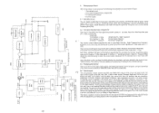
... P. r- TRG cow SUB CONT DAC2 VIDEO OUT Pt STATE DDC coo MC 4)*(.46MOgilikoi A 1 •1 03 ffi Er53 ;2 ;2 it. C pos V u0 IRE H. W. Y. TRP i1 FH0 VIDE ThAk ?IF +B o -SWITCH INS POKER SUPPLY +B 017 mat 01:7 1 R AM RAVER SUB2 P. B SYNC SDA 0 SCL. S. n CONTROL P. W, B. POWER SUB 2 P. GAIN CONTROL CLP BLK H&V SYNC SIGNAL CONTROL OSD -4-CLAMP MUTE - 1 3W3 or 15P-DSUB H, SYNC C.) V. B. W. B RS232C* I 1 agt\C V.S1N 0 O 0 O 0 O 0 0 HCU...
... P. r- TRG cow SUB CONT DAC2 VIDEO OUT Pt STATE DDC coo MC 4)*(.46MOgilikoi A 1 •1 03 ffi Er53 ;2 ;2 it. C pos V u0 IRE H. W. Y. TRP i1 FH0 VIDE ThAk ?IF +B o -SWITCH INS POKER SUPPLY +B 017 mat 01:7 1 R AM RAVER SUB2 P. B SYNC SDA 0 SCL. S. n CONTROL P. W, B. POWER SUB 2 P. GAIN CONTROL CLP BLK H&V SYNC SIGNAL CONTROL OSD -4-CLAMP MUTE - 1 3W3 or 15P-DSUB H, SYNC C.) V. B. W. B RS232C* I 1 agt\C V.S1N 0 O 0 O 0 O 0 0 HCU...
Service Manual
Page 25
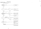
... circuits: Power circuit, Horizontal deflection circuit, High voltage limitter circuit Check supply Voltage AC100-120V/ AC200-240V Abnormal Normal Trouble outside the character monitor Check F901 Abnormal Normal Replace F901 Normal Abnormal 1920, C920, C902, C903, C904, C905 (Change the C97(B) Power Sub 1 Board) In key mode,10 seconds after finishing operation, power LED only light. (Abnormal) No Yes (Normal) The power LED is damaged. Change the Microprocessor...
... circuits: Power circuit, Horizontal deflection circuit, High voltage limitter circuit Check supply Voltage AC100-120V/ AC200-240V Abnormal Normal Trouble outside the character monitor Check F901 Abnormal Normal Replace F901 Normal Abnormal 1920, C920, C902, C903, C904, C905 (Change the C97(B) Power Sub 1 Board) In key mode,10 seconds after finishing operation, power LED only light. (Abnormal) No Yes (Normal) The power LED is damaged. Change the Microprocessor...
Service Manual
Page 26
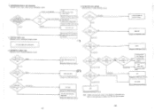
...) 1201 (Change the C97(B)Video/V Board) Normal (30-75V) 1203 (Change the C97(B) Video/V Board) Note : Trouble in the red circuit is shown in this diagram as representative color. SYNCHRONIZATION IS NOT OBTAINED Relevant circuit : Sync. is not obtained. Abnormal Normal Check OV the voltage of 1201 17 pin Normal (1.5-4.0V) Abnorma l Microprocessor Unit is damaged. VERTICAL SINGLE LINE Relevant circuit : Horizontal output circuit...
...) 1201 (Change the C97(B)Video/V Board) Normal (30-75V) 1203 (Change the C97(B) Video/V Board) Note : Trouble in the red circuit is shown in this diagram as representative color. SYNCHRONIZATION IS NOT OBTAINED Relevant circuit : Sync. is not obtained. Abnormal Normal Check OV the voltage of 1201 17 pin Normal (1.5-4.0V) Abnorma l Microprocessor Unit is damaged. VERTICAL SINGLE LINE Relevant circuit : Horizontal output circuit...
Service Manual
Page 27
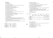
... +B voltage value as indicate on table 2, for frequency Horizontal high(fHH), and adjust R724 to the value indicated on table 2. (8) Receive the signal 43W for fHL and adjust the fHOL to 6.2 ± 0.05V using R726. (11) Turn the switch of signal 70A. (5) Connect a Digital multimeter between the T1(GND)and T2 on the CRT neck board. (6) Adjust CDT heater voltage to 43.3 ± 0.1kHz...
... +B voltage value as indicate on table 2, for frequency Horizontal high(fHH), and adjust R724 to the value indicated on table 2. (8) Receive the signal 43W for fHL and adjust the fHOL to 6.2 ± 0.05V using R726. (11) Turn the switch of signal 70A. (5) Connect a Digital multimeter between the T1(GND)and T2 on the CRT neck board. (6) Adjust CDT heater voltage to 43.3 ± 0.1kHz...
Service Manual
Page 28
... the followings to obtain these numbers. 1) Reset Sub Brightness to 1.57V (BF) or 3.4V (40). 2) Reset Sub Brightness to 0.63V (DF) or 4.4V (20). 3) Reset G2 to 430V or 370V 4r) 3.2 White balance adjustment (Color 2) (1) Receive a signal of 70A with a blank signal pattem.(Black video) (2) Connect a high impedance voltmeter (more than 1000M0) to the Screen terminal (G2) on the CRT neck board. The monitor must have been warmed...
... the followings to obtain these numbers. 1) Reset Sub Brightness to 1.57V (BF) or 3.4V (40). 2) Reset Sub Brightness to 0.63V (DF) or 4.4V (20). 3) Reset G2 to 430V or 370V 4r) 3.2 White balance adjustment (Color 2) (1) Receive a signal of 70A with a blank signal pattem.(Black video) (2) Connect a high impedance voltmeter (more than 1000M0) to the Screen terminal (G2) on the CRT neck board. The monitor must have been warmed...
Service Manual
Page 29
... 16V C2HG 0800335R EL 220MF 16V .. - 38 - Before replacing any of there components,read carefully,the PRODUCT SAFETY NOTICE of FBT Controls REPLACEMENT PARTS LIST PRODUCT SAFETY NOTE : Components marked with a full screen "E" characters. (2) Set user Contrast control to its maximum. (3) Set user Brightness control so that the back ground raster is just diminished. (4) Adjust S-Focus control on the FBT so that focus at the...
... 16V C2HG 0800335R EL 220MF 16V .. - 38 - Before replacing any of there components,read carefully,the PRODUCT SAFETY NOTICE of FBT Controls REPLACEMENT PARTS LIST PRODUCT SAFETY NOTE : Components marked with a full screen "E" characters. (2) Set user Contrast control to its maximum. (3) Set user Brightness control so that the back ground raster is just diminished. (4) Adjust S-Focus control on the FBT so that focus at the...
Service Manual
Page 30
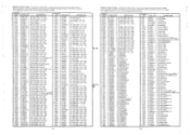
...0.47MF +-10% 200V NO. DESCRIPTION ,. C746 ,! Don't degrade the safety of the receiver through improper servicing. DESCRIPTION 0890089 CD 1500PF +- 10% 50V NO. ,f C748 PART NO. C774 0262787F PP 0.18PF +-5% 200V (except CM803U) C98F 0245603 CD 220PF +-10% 1KV C774 ... : Components marked with a have special characteristics important to safety. 1 Before replacing any of there components,read carefully,the PRODUCT SAFETY NOTICE of this Service Manual. Don't degrade the safety of this Service Manual. C745 ! C905 A. C744 ,:. C956 0880032 PF 1200PF +-10% 50V...
...0.47MF +-10% 200V NO. DESCRIPTION ,. C746 ,! Don't degrade the safety of the receiver through improper servicing. DESCRIPTION 0890089 CD 1500PF +- 10% 50V NO. ,f C748 PART NO. C774 0262787F PP 0.18PF +-5% 200V (except CM803U) C98F 0245603 CD 220PF +-10% 1KV C774 ... : Components marked with a have special characteristics important to safety. 1 Before replacing any of there components,read carefully,the PRODUCT SAFETY NOTICE of this Service Manual. Don't degrade the safety of this Service Manual. C745 ! C905 A. C744 ,:. C956 0880032 PF 1200PF +-10% 50V...
Service Manual
Page 31
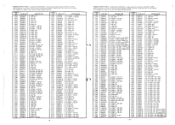
... R2JR R2KB R2KG R2KR R2LB R2L0 R2LR R2PB R2PG R2PR R2OB R200 R2OR R2RB R2RG R2RR R2SB R2SG R2SR _ PART NO. 0700054 0187060 0187058 0700054 0700047 0700041 0188154 0700048 0160501U 0700064 0700066 0700051 0700049 0700064 0700061 0700061 0700061 0700047 0700048...SYMBOL NO. Don't degrade the safety of the receiver through improper servicing. Don't degrade the safety of the receiver through improper servicing. Before replacing any of there components.read carefully,the PRODUCT SAFETY NOTICE of this Service Manual. PRODUCT SAFETY NOTE : Components marked with a N have special ...
... R2JR R2KB R2KG R2KR R2LB R2L0 R2LR R2PB R2PG R2PR R2OB R200 R2OR R2RB R2RG R2RR R2SB R2SG R2SR _ PART NO. 0700054 0187060 0187058 0700054 0700047 0700041 0188154 0700048 0160501U 0700064 0700066 0700051 0700049 0700064 0700061 0700061 0700061 0700047 0700048...SYMBOL NO. Don't degrade the safety of the receiver through improper servicing. Don't degrade the safety of the receiver through improper servicing. Before replacing any of there components.read carefully,the PRODUCT SAFETY NOTICE of this Service Manual. PRODUCT SAFETY NOTE : Components marked with a N have special ...
Service Manual
Page 32
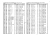
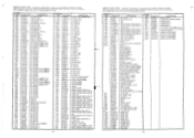
...Q779 Q780 Q781 Q782 Q783 0784 Q785 0800 0801 0804 0820 0821 0822 0870 Q871 ! Before replacing any of there components,read carefully,the PRODUCT SAFETY NOTICE of this Service Manual. R757 0119631 MF 10K OHM 4-1% 1/8W R910 0140952M MF 120K OHM 4-5% 1/2W R758 ...4-5% 1/8W ! SYMBOL SYMBOL NO. R751 PART NO. Before replacing any of there components,read carefuily.the PRODUCT SAFETY NOTICE of this Service Manual. DESCRIPTION 0100065 CF 1K OHM 4-5% 1/8W .. ,_r. SYMBOL NO. 1992 ! 19A1 t. 19A2 ! Q910 PART NO. 2020501 2366721 2386232 CF10432G CF10432G CP02361 ...
...Q779 Q780 Q781 Q782 Q783 0784 Q785 0800 0801 0804 0820 0821 0822 0870 Q871 ! Before replacing any of there components,read carefully,the PRODUCT SAFETY NOTICE of this Service Manual. R757 0119631 MF 10K OHM 4-1% 1/8W R910 0140952M MF 120K OHM 4-5% 1/2W R758 ...4-5% 1/8W ! SYMBOL SYMBOL NO. R751 PART NO. Before replacing any of there components,read carefuily.the PRODUCT SAFETY NOTICE of this Service Manual. DESCRIPTION 0100065 CF 1K OHM 4-5% 1/8W .. ,_r. SYMBOL NO. 1992 ! 19A1 t. 19A2 ! Q910 PART NO. 2020501 2366721 2386232 CF10432G CF10432G CP02361 ...
Service Manual
Page 33
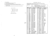
... SCREW 4X16 MM 5X2O WASHER BASED SCREW SCREW M3X10 3X8 CE KNURL SCREW 3X6 CE KNURL SCREW RUBBER FOOT 4X8 PAN HEAD SCREW LOCKING WASHER 4 POWER BUTTON CONTROL PANEL S-ASS'Y BEZEL S-ASS'Y TOP CUSHION BOTTOM CUSHION POLYETHYLENE COVER 1100+1000 CF MAGNET CPT EARTH WIRE PIN JACK MAGNET PEACE WEDGE COIL FERRITE SHEET CPT SOCKET FUSE HOLDER AC POWER SUPPLY JACK 3P PLUG PIN WITH BASE AC CORD SET...
... SCREW 4X16 MM 5X2O WASHER BASED SCREW SCREW M3X10 3X8 CE KNURL SCREW 3X6 CE KNURL SCREW RUBBER FOOT 4X8 PAN HEAD SCREW LOCKING WASHER 4 POWER BUTTON CONTROL PANEL S-ASS'Y BEZEL S-ASS'Y TOP CUSHION BOTTOM CUSHION POLYETHYLENE COVER 1100+1000 CF MAGNET CPT EARTH WIRE PIN JACK MAGNET PEACE WEDGE COIL FERRITE SHEET CPT SOCKET FUSE HOLDER AC POWER SUPPLY JACK 3P PLUG PIN WITH BASE AC CORD SET...


