
Owners Guide
Page 4
models: For optional accessories, please access our web site at: www.hitachi.us/tv Note: Please visit our website for use Accessories Check to make sure you have the following accessories before disposing of the packing material. &#... injury. Press down and sliding the back cover off. 2. This plasma television product is not recommended. First time use only with Hitachi 42HDX99 and 42HDT79. MENU EXIT FAV CH INPUTS º Ferrite Core on the ceiling does not provide adequate ventilation for the electronics or proper support for the front glass panel...
models: For optional accessories, please access our web site at: www.hitachi.us/tv Note: Please visit our website for use Accessories Check to make sure you have the following accessories before disposing of the packing material. &#... injury. Press down and sliding the back cover off. 2. This plasma television product is not recommended. First time use only with Hitachi 42HDX99 and 42HDT79. MENU EXIT FAV CH INPUTS º Ferrite Core on the ceiling does not provide adequate ventilation for the electronics or proper support for the front glass panel...

Owners Guide
Page 8
... laserdisc players with shielded video and audio cables that sell audio/video products. Before purchasing any cables, be sure of the output and input connector types required by the various components and the length of each cable. 300-Ohm Twin Lead Cable This outdoor antenna cable must place.... Phono Cable Used on the rear jack panel and side control panel. Cables can be connected to an antenna adapter (300-Ohm to inputs and outputs located on all standard video and audio cable which connect to control your digital television to the IR output of common connectors. ...
... laserdisc players with shielded video and audio cables that sell audio/video products. Before purchasing any cables, be sure of the output and input connector types required by the various components and the length of each cable. 300-Ohm Twin Lead Cable This outdoor antenna cable must place.... Phono Cable Used on the rear jack panel and side control panel. Cables can be connected to an antenna adapter (300-Ohm to inputs and outputs located on all standard video and audio cable which connect to control your digital television to the IR output of common connectors. ...

Owners Guide
Page 9
... is included in DVD, PVR/VCR, or AMP/CD mode. MODE INDICATOR Turns on your HITACHI Plasma TV, the new remote control is used to change backlight mode. Also used as a cursor to navigate through the OSD, INPUTS, and AV NET menu systems. (-) BUTTON (TV,STB) The (-) button is used to ... BUTTON (TV, STB, CBL, PVR) Accesses the TV Guide On ScreenTM system (see pages 25-43 for numeric entry when navigating through the OSD and INPUT menu systems. The Select button is designed to operate different types of devices, such as channel information. EXIT BUTTON (TV, CBL, STB, PVR/VCR) ...
... is included in DVD, PVR/VCR, or AMP/CD mode. MODE INDICATOR Turns on your HITACHI Plasma TV, the new remote control is used to change backlight mode. Also used as a cursor to navigate through the OSD, INPUTS, and AV NET menu systems. (-) BUTTON (TV,STB) The (-) button is used to ... BUTTON (TV, STB, CBL, PVR) Accesses the TV Guide On ScreenTM system (see pages 25-43 for numeric entry when navigating through the OSD and INPUT menu systems. The Select button is designed to operate different types of devices, such as channel information. EXIT BUTTON (TV, CBL, STB, PVR/VCR) ...

Owners Guide
Page 10
... stand-by mode. ባ MENU/SELECT button This button allows you to enter the MENU, making it possible to set TV features to access the INPUT menu. NOTE: When the "MAIN POWER" button is set to OFF or the TV is recommended to leave the "MAIN POWER" to ON condition (lights... devices such as the cursor down (̄) and up (̆) buttons when in the top right corner of the 55" model is for reference). ብ INPUT/EXIT button Press this button to exit the MENU mode. NOTE: The Rear View of the TV screen. The volume level will stop and may...
... stand-by mode. ባ MENU/SELECT button This button allows you to enter the MENU, making it possible to set TV features to access the INPUT menu. NOTE: When the "MAIN POWER" button is set to OFF or the TV is recommended to leave the "MAIN POWER" to ON condition (lights... devices such as the cursor down (̄) and up (̆) buttons when in the top right corner of the 55" model is for reference). ብ INPUT/EXIT button Press this button to exit the MENU mode. NOTE: The Rear View of the TV screen. The volume level will stop and may...

Owners Guide
Page 11
... ቪ LEARNING AV NET sensor Point your equipment's remote control at this capability, such as a DVD player or Set Top Box. In this input. Your HITACHI Plasma TV will illuminate. TV MAIN POWER is shown. picture is ON ; Lights Red Off Off Blinking Blue OFF. (Stand-by mode (lights ...red) when not in use composite video signal for connecting equipment with no signal input except antenna (no picture is ON with this area...
... ቪ LEARNING AV NET sensor Point your equipment's remote control at this capability, such as a DVD player or Set Top Box. In this input. Your HITACHI Plasma TV will illuminate. TV MAIN POWER is shown. picture is ON ; Lights Red Off Off Blinking Blue OFF. (Stand-by mode (lights ...red) when not in use composite video signal for connecting equipment with no signal input except antenna (no picture is ON with this area...

Owners Guide
Page 12
...*Manufactured under license from the source all digital interface for use only. S-VIDEO output may be used for recording, only when the input is not intended for consumer electronics. Your component outputs may use composite video signal for your external devices such as VCRs, camcorders, ...-Top-Boxes or DVD players equipped with personal computers. 2. In this case, connect the components B-Y output to the TV's PB input and the components R-Y output to your audio device that pristine high-definition images retain the highest video quality from Dolby Laboratories. It ...
...*Manufactured under license from the source all digital interface for use only. S-VIDEO output may be used for recording, only when the input is not intended for consumer electronics. Your component outputs may use composite video signal for your external devices such as VCRs, camcorders, ...-Top-Boxes or DVD players equipped with personal computers. 2. In this case, connect the components B-Y output to the TV's PB input and the components R-Y output to your audio device that pristine high-definition images retain the highest video quality from Dolby Laboratories. It ...
Owners Guide
Page 13
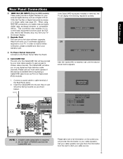
...to control basic equipment functions (such as Point of card should be provided by means of the Rear Panel Jacks. 2. Acquiring Data. Hitachi will notify you if a software upgrade is properly installed or removed, the TV will be facing towards you enable video and audio ... a compatible device. Digital Cable INSERT If the CableCARD is required for your TV. First time use Rear Panel Connections ቫ IEEE1394 (DV INPUT) (Only for HDX models) These jacks provide a digital interface for your external digital devices, such as shown below appears. Connect a coaxial ...
...to control basic equipment functions (such as Point of card should be provided by means of the Rear Panel Jacks. 2. Acquiring Data. Hitachi will notify you if a software upgrade is properly installed or removed, the TV will be facing towards you enable video and audio ... a compatible device. Digital Cable INSERT If the CableCARD is required for your TV. First time use Rear Panel Connections ቫ IEEE1394 (DV INPUT) (Only for HDX models) These jacks provide a digital interface for your external digital devices, such as shown below appears. Connect a coaxial ...

Owners Guide
Page 14
... Wrap once the USB cable on the ferrite core near the Photo Input as shown in the following examples: Left Side Panel INPUT 5 Left Side Panel R L/MONO AUDIO PR PB Y / VIDEO PHOTO INPUT R L/MONO AUDIO PR PB Y / VIDEO PHOTO INPUT First time use Note : Special device cables will be abnormal. Connecting... a convenience to allow you do not, the played back picture may be according to the own device specifications. Video Camera NOTE: 1. PHOTO INPUT Ferrite Core USB Cable Digital Camera 14 Fold and close the ferrite core while being careful not to left side panel jacks...
... Wrap once the USB cable on the ferrite core near the Photo Input as shown in the following examples: Left Side Panel INPUT 5 Left Side Panel R L/MONO AUDIO PR PB Y / VIDEO PHOTO INPUT R L/MONO AUDIO PR PB Y / VIDEO PHOTO INPUT First time use Note : Special device cables will be abnormal. Connecting... a convenience to allow you do not, the played back picture may be according to the own device specifications. Video Camera NOTE: 1. PHOTO INPUT Ferrite Core USB Cable Digital Camera 14 Fold and close the ferrite core while being careful not to left side panel jacks...

Owners Guide
Page 15
... 28). DIGITAL OUTPUT OUTPUT R L DVI DIGITAL OUTPUT CAPABILITY DVD , Set Top Box, Video Game Console. Completely insert connection cord plugs when connecting to select the Input of your Plasma TV is dependent on the model and features of each component for the location of HDTV Set-Top-Box or DVD Player... and audio cables should be abnormal. If you use DVI to HDMI Cable Note : Special device cables will need to modify them to show the INPUTS menu. The exact arrangement you do not, the played back picture may need to your choice. Right Side Panel Left Side Panel...
... 28). DIGITAL OUTPUT OUTPUT R L DVI DIGITAL OUTPUT CAPABILITY DVD , Set Top Box, Video Game Console. Completely insert connection cord plugs when connecting to select the Input of your Plasma TV is dependent on the model and features of each component for the location of HDTV Set-Top-Box or DVD Player... and audio cables should be abnormal. If you use DVI to HDMI Cable Note : Special device cables will need to modify them to show the INPUTS menu. The exact arrangement you do not, the played back picture may need to your choice. Right Side Panel Left Side Panel...

Owners Guide
Page 16
... AUDIO OUT DVI to HDMI DV or 1394 OUTPUT DVHS DV or 1394 OUTPUT CAPABILITY "Only HDX Models" OUTPUT Y PB/CB PR/CR L R Optional S-VIDEO V L R INPUT S-VIDEO V L R OUTPUT Y PB PR L R OUTPUT HDMI to HDMI HDMI OUTPUT DVD Player VCR #2 Laserdisc player, VCR, camcorder, etc. (PROVIDED) CONNECT TO G-LINK/IR OUT CONNECT...
... AUDIO OUT DVI to HDMI DV or 1394 OUTPUT DVHS DV or 1394 OUTPUT CAPABILITY "Only HDX Models" OUTPUT Y PB/CB PR/CR L R Optional S-VIDEO V L R INPUT S-VIDEO V L R OUTPUT Y PB PR L R OUTPUT HDMI to HDMI HDMI OUTPUT DVD Player VCR #2 Laserdisc player, VCR, camcorder, etc. (PROVIDED) CONNECT TO G-LINK/IR OUT CONNECT...

Owners Guide
Page 17
...16). In this feature. Connecting the television directly to the Audio /Video output of a Set-Top-Box will assure a more information on line input-output connections. • Connect only 1 component (VCR, DVD player, camcorder, etc.) to the operating guide of S-VIDEO type. • When using ... protection systems and the picture will be abnormal, when using the Y-PBPR, and HDMI input jacks. • Input 1 , 2 or 5 can be used for recording only when the input is recommended to the TV's PR input. • Your component outputs may be necessary to adjust TINT to obtain optimum picture ...
...16). In this feature. Connecting the television directly to the Audio /Video output of a Set-Top-Box will assure a more information on line input-output connections. • Connect only 1 component (VCR, DVD player, camcorder, etc.) to the operating guide of S-VIDEO type. • When using ... protection systems and the picture will be abnormal, when using the Y-PBPR, and HDMI input jacks. • Input 1 , 2 or 5 can be used for recording only when the input is recommended to the TV's PR input. • Your component outputs may be necessary to adjust TINT to obtain optimum picture ...

Owners Guide
Page 18
...Player NOTE: 1. The picture and sound that is played back will be used for reference). CONNECTING AN S-VIDEO AND STEREO AUDIO SOURCE TO INPUT 1, 2 1. Connect the cable from the VCR or laserdisc player. 5. Completely insert the connection cord plugs when connecting to rear panel jacks.... cord plugs when connecting to rear panel jacks. Connect the cable from the VCR or laserdisc player. Press the INPUTS button, then select INPUT 1 from the INPUTS menu to the INPUT (S-VIDEO) jack, as shown on line inputoutput connections. 3. A single VCR can be abnormal if the connection ...
...Player NOTE: 1. The picture and sound that is played back will be used for reference). CONNECTING AN S-VIDEO AND STEREO AUDIO SOURCE TO INPUT 1, 2 1. Connect the cable from the VCR or laserdisc player. 5. Completely insert the connection cord plugs when connecting to rear panel jacks.... cord plugs when connecting to rear panel jacks. Connect the cable from the VCR or laserdisc player. Press the INPUTS button, then select INPUT 1 from the INPUTS menu to the INPUT (S-VIDEO) jack, as shown on line inputoutput connections. 3. A single VCR can be abnormal if the connection ...
Owners Guide
Page 19
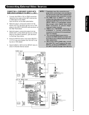
.... 5. HDMI is not a "NETWORK" technology. NOTE: 1. Completely insert the connection cord plugs when connecting to the HDMI input as your HDMI INPUT(1 , 2 or 5). (For INPUT 5 please see page 15 for delivery of uncompressed video to HDMI Cable or DIGITAL OUTPUT Back of HDTV Set-Top-Box or... system called High-bandwidth Digital Content Protection (HDCP). First time use Connecting External Video Sources CONNECTING A COMPONENT SOURCE WITH HDMI OR DVI CAPABILITY TO INPUT 1, 2 OR 5 1. Connect the HDMI or DVI to HDMI connection cable from the AUDIO OUT R of the HDTV set top box or ...
.... 5. HDMI is not a "NETWORK" technology. NOTE: 1. Completely insert the connection cord plugs when connecting to the HDMI input as your HDMI INPUT(1 , 2 or 5). (For INPUT 5 please see page 15 for delivery of uncompressed video to HDMI Cable or DIGITAL OUTPUT Back of HDTV Set-Top-Box or... system called High-bandwidth Digital Content Protection (HDCP). First time use Connecting External Video Sources CONNECTING A COMPONENT SOURCE WITH HDMI OR DVI CAPABILITY TO INPUT 1, 2 OR 5 1. Connect the HDMI or DVI to HDMI connection cable from the AUDIO OUT R of the HDTV set top box or ...
Owners Guide
Page 20
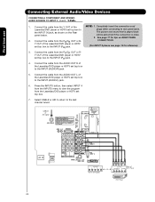
... REAR PANEL 2. Connect the cable from the PR/CR OUT or RY OUT of the Laserdisc/DVD player or HDTV set top box to the INPUT (AUDIO/R) jack. 5. Select CABLE or AIR to return to rear panel jacks. Connect the cable from the AUDIO OUT L of the Laserdisc/DVD player or... is played back panel below. Connect the cable from the Laserdisc/DVD player or HDTV set top box to the INPUT (AUDIO/L) jack. 6. Press the INPUTS button, then select INPUT 4 from the INPUTS menu to view the program from the PB/CB OUT or BY OUT of VIDEO AUDIO DVD Player OR PR/CR...
... REAR PANEL 2. Connect the cable from the PR/CR OUT or RY OUT of the Laserdisc/DVD player or HDTV set top box to the INPUT (AUDIO/R) jack. 5. Select CABLE or AIR to return to rear panel jacks. Connect the cable from the AUDIO OUT L of the Laserdisc/DVD player or... is played back panel below. Connect the cable from the Laserdisc/DVD player or HDTV set top box to the INPUT (AUDIO/L) jack. 6. Press the INPUTS button, then select INPUT 4 from the INPUTS menu to view the program from the PB/CB OUT or BY OUT of VIDEO AUDIO DVD Player OR PR/CR...

Owners Guide
Page 21
... Air signal Stereo System Amplifier or DVD Player Optional 2. Connect the cable from the Optical out to the Optical input of the VCR or the laserdisc player to the previous channel. (For INPUT 5 please see page 14 for reference). Connect the cable from the AUDIO IN R of the VCR or the ... OUTPUT (AUDIO/R) jack on the TV Rear Panel. Select CABLE or AIR from the AUDIO OUT of the VCR or the laserdisc player to the INPUT (MONO)/L(AUDIO) jack. 3. Connecting S-Video: Connect the cable from the Rear Panel is controlled by the amplifier, not by the Plasma Television. If both are...
... Air signal Stereo System Amplifier or DVD Player Optional 2. Connect the cable from the Optical out to the Optical input of the VCR or the laserdisc player to the previous channel. (For INPUT 5 please see page 14 for reference). Connect the cable from the AUDIO IN R of the VCR or the ... OUTPUT (AUDIO/R) jack on the TV Rear Panel. Select CABLE or AIR from the AUDIO OUT of the VCR or the laserdisc player to the INPUT (MONO)/L(AUDIO) jack. 3. Connecting S-Video: Connect the cable from the Rear Panel is controlled by the amplifier, not by the Plasma Television. If both are...

Owners Guide
Page 22
...OUT terminal of the Audio/Video components for the AV Network to control. Setup Set the Menu Options Set The Screen Saver Set The Inputs Set AV NET Set The Closed Captions Set The Output Terminals Set The Quick Start Options Reset the Software Move SEL Return NOTE: 1.... of four external components. 2. The IR Blaster must be used to highlight SETUP. Follow the Setup procedure on pages 68-75. First time use your Hitachi Plasma Television and external Audio/Video equipment (VCR and DVD Player). Infrared Sensor IR Blaster V L R OUTPUT VCR Infrared Sensor OUTPUT Y PB/CB PR/CR...
...OUT terminal of the Audio/Video components for the AV Network to control. Setup Set the Menu Options Set The Screen Saver Set The Inputs Set AV NET Set The Closed Captions Set The Output Terminals Set The Quick Start Options Reset the Software Move SEL Return NOTE: 1.... of four external components. 2. The IR Blaster must be used to highlight SETUP. Follow the Setup procedure on pages 68-75. First time use your Hitachi Plasma Television and external Audio/Video equipment (VCR and DVD Player). Infrared Sensor IR Blaster V L R OUTPUT VCR Infrared Sensor OUTPUT Y PB/CB PR/CR...

Owners Guide
Page 24
... option (see page 31). 2. Connect the IEEE1394 cable from the output of the component with one another. This connection also enables you to the IEEE1394 input terminals shown below. It will be received by the TV. First time use Connecting External Video Sources CONNECTING A COMPONENT SOURCE WITH DIGITAL INTERFACE CAPABILITY TO...
... option (see page 31). 2. Connect the IEEE1394 cable from the output of the component with one another. This connection also enables you to the IEEE1394 input terminals shown below. It will be received by the TV. First time use Connecting External Video Sources CONNECTING A COMPONENT SOURCE WITH DIGITAL INTERFACE CAPABILITY TO...

Owners Guide
Page 26
... entering your device ቧ ቩ code to program the remote (see pages 36-41). ቨ ቯ You can also use this button in an optional Input access feature (see - ቫ ቱ page 35). ተ / ቲ ታ ታ Freeze ቴ ት Freeze Freeze Freeze Freeze 26...
... entering your device ቧ ቩ code to program the remote (see pages 36-41). ቨ ቯ You can also use this button in an optional Input access feature (see - ቫ ቱ page 35). ተ / ቲ ታ ታ Freeze ቴ ት Freeze Freeze Freeze Freeze 26...

Owners Guide
Page 27
... on page 98. 1 • Antenna-Digital Channel (4:3) • S-Video/Video 4:3/Letter Input (Auto Aspect: On) • HDMI-480i/480p 4:3/ Letter Input (Auto Aspect: On) IMA G E INPUT • Component-480i/480p 4:3/ Letter Input (Auto Aspect: On) • IEEE1394 (4:3) (Only HDX models) Note: Please see Appendix ...A on page 98. • S-Video/Video 16:9 Input (Auto Aspect: On) • HDMI-480i/480p 16:9 Input (Auto Aspect: On) • Component-480i/480p IMA G E INPUT 1 16:9 Input (Auto Aspect: On) Note: Please see Appendix A on page 98. • ...
... on page 98. 1 • Antenna-Digital Channel (4:3) • S-Video/Video 4:3/Letter Input (Auto Aspect: On) • HDMI-480i/480p 4:3/ Letter Input (Auto Aspect: On) IMA G E INPUT • Component-480i/480p 4:3/ Letter Input (Auto Aspect: On) • IEEE1394 (4:3) (Only HDX models) Note: Please see Appendix ...A on page 98. • S-Video/Video 16:9 Input (Auto Aspect: On) • HDMI-480i/480p 16:9 Input (Auto Aspect: On) • Component-480i/480p IMA G E INPUT 1 16:9 Input (Auto Aspect: On) Note: Please see Appendix A on page 98. • ...
Owners Guide
Page 28
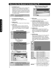
... in TV mode, press this button to access the INPUTS menu. Press the CURSOR PAD toward desired direction and press the SELECT button to INPUT 1 INFO S-IN: 1 480i 3:17PM INPUT 1 INPUT 2 INPUT 3 INPUT 4 Photo Input IEEE 1394 Air / Cable Input 1 Input 2 Move SEL Sel. DTvCC 1080i Air 15-1 KPBS... compete with Closed Captioning. Select Day modes for amore detailed picture (see page 31). 28 Select to choose INPUT 4. Pressing the INPUTS Closed Caption setting Audio Source Selection DIGITAL CHANNELS Digital Closed Caption This icon will exit all On-Screen Displays. ...
... in TV mode, press this button to access the INPUTS menu. Press the CURSOR PAD toward desired direction and press the SELECT button to INPUT 1 INFO S-IN: 1 480i 3:17PM INPUT 1 INPUT 2 INPUT 3 INPUT 4 Photo Input IEEE 1394 Air / Cable Input 1 Input 2 Move SEL Sel. DTvCC 1080i Air 15-1 KPBS... compete with Closed Captioning. Select Day modes for amore detailed picture (see page 31). 28 Select to choose INPUT 4. Pressing the INPUTS Closed Caption setting Audio Source Selection DIGITAL CHANNELS Digital Closed Caption This icon will exit all On-Screen Displays. ...


