End User License Agreement
Page 2
... conditions set forth elsewhere in such recovery solution shall be used for the upgrade. The use of a hard disk drive-based solution, an external media-based recovery solution (e.g. To use technical information you fail to United States copyright, trade secret, and trademark law, as well as eligible for restoring the hard disk of such license. In case of the Software Product to the Recovery Solution. The initial user of the Software...
... conditions set forth elsewhere in such recovery solution shall be used for the upgrade. The use of a hard disk drive-based solution, an external media-based recovery solution (e.g. To use technical information you fail to United States copyright, trade secret, and trademark law, as well as eligible for restoring the hard disk of such license. In case of the Software Product to the Recovery Solution. The initial user of the Software...
Safety and Regulatory Information Desktops, Thin Clients, and Personal Workstations
Page 5
... 9 New Zealand Modem Statements 9 Voice Support ...10 TV Antenna Connectors Protection ...11 External Television Antenna Grounding 11 Lightning Protection ...11 ENWW v Table of contents 1 Safety Notices Important Safety Information ...1 Installation Conditions ...2 Battery Replacement Notice ...2 Headset and Earphone Volume Level Notice 3 German Ergonomics Notice ...3 Laser Safety ...3 CDRH Regulations ...3 Compliance with International Regulations 4 Laser Product Label ...4 Laser Information ...4 Power Supply and Power Cord Set...
... 9 New Zealand Modem Statements 9 Voice Support ...10 TV Antenna Connectors Protection ...11 External Television Antenna Grounding 11 Lightning Protection ...11 ENWW v Table of contents 1 Safety Notices Important Safety Information ...1 Installation Conditions ...2 Battery Replacement Notice ...2 Headset and Earphone Volume Level Notice 3 German Ergonomics Notice ...3 Laser Safety ...3 CDRH Regulations ...3 Compliance with International Regulations 4 Laser Product Label ...4 Laser Information ...4 Power Supply and Power Cord Set...
Safety and Regulatory Information Desktops, Thin Clients, and Personal Workstations
Page 17
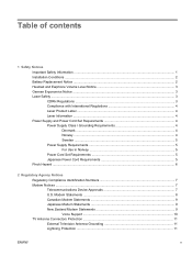
... Electrical Code, ANSI/NFPA 70, provides information with regard to proper electrical grounding of the mast and supporting structure, grounding of the lead-in Wire ENWW TV Antenna Connectors Protection 11 Lightning Protection For added protection of...Service Equipment 2 Power Service Grounding Electrode System (NEC Art 250, Part H) 3 Ground Clamps 4 Grounding Conductors (NEC Section 810-21) 5 Antenna Discharge Unit (NEC Section 810-20) 6 Ground Clamp 7 Antenna Lead-in wire to an antenna-discharge unit, size of grounding conductors, location of antenna-discharge unit, connection...
... Electrical Code, ANSI/NFPA 70, provides information with regard to proper electrical grounding of the mast and supporting structure, grounding of the lead-in Wire ENWW TV Antenna Connectors Protection 11 Lightning Protection For added protection of...Service Equipment 2 Power Service Grounding Electrode System (NEC Art 250, Part H) 3 Ground Clamps 4 Grounding Conductors (NEC Section 810-21) 5 Antenna Discharge Unit (NEC Section 810-20) 6 Ground Clamp 7 Antenna Lead-in wire to an antenna-discharge unit, size of grounding conductors, location of antenna-discharge unit, connection...
Hardware Reference Guide - dx2810 Microtower Model
Page 7
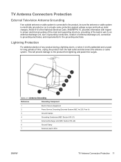
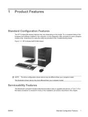
... upgrade and service. 1 Product Features Standard Configuration Features The HP Compaq Microtower features may be different than your computer model. Instructions for many of the hardware and software installed in the Troubleshooting Guide. The illustration shown above may vary depending on some computer models only). ENWW Standard Configuration Features 1 A Torx T-15 or flat blade screwdriver is needed for using the utility are provided in the computer, run the diagnostic utility...
... upgrade and service. 1 Product Features Standard Configuration Features The HP Compaq Microtower features may be different than your computer model. Instructions for many of the hardware and software installed in the Troubleshooting Guide. The illustration shown above may vary depending on some computer models only). ENWW Standard Configuration Features 1 A Torx T-15 or flat blade screwdriver is needed for using the utility are provided in the computer, run the diagnostic utility...

Hardware Reference Guide - dx2810 Microtower Model
Page 9
... a PCI Express x16 graphics card is installed in Computer Setup to the Computer Setup (F10) Utility Guide. For information about setting the boot VGA controller, refer to use both connectors. ENWW Rear Panel Components 3 Rear Panel Components Figure 1-3 Rear Panel Components Table 1-2 Rear Panel Components 1 Power Cord Connector 7 Line-Out Connector for powered audio devices (green) 2 Voltage Select Switch 8 Microphone Connector (pink) 3 RJ-45 Network Connector 9 Universal Serial Bus (USB) Ports 4 Parallel Port (purple) 10 VGA Monitor Connector (blue) 5 PS/2 Mouse Connector...
... a PCI Express x16 graphics card is installed in Computer Setup to the Computer Setup (F10) Utility Guide. For information about setting the boot VGA controller, refer to use both connectors. ENWW Rear Panel Components 3 Rear Panel Components Figure 1-3 Rear Panel Components Table 1-2 Rear Panel Components 1 Power Cord Connector 7 Line-Out Connector for powered audio devices (green) 2 Voltage Select Switch 8 Microphone Connector (pink) 3 RJ-45 Network Connector 9 Universal Serial Bus (USB) Ports 4 Parallel Port (purple) 10 VGA Monitor Connector (blue) 5 PS/2 Mouse Connector...

Hardware Reference Guide - dx2810 Microtower Model
Page 21
... the contacts. Remove all removable media, such as single channel. ● In any of the power-on the system board. The memory module sockets have more information, refer to Appendix D, Electrostatic Discharge on state, voltage is always supplied to touch any mode, the maximum operational speed is spread between the two channels. Doing so may damage the module. 1. Turn off the...
... the contacts. Remove all removable media, such as single channel. ● In any of the power-on the system board. The memory module sockets have more information, refer to Appendix D, Electrostatic Discharge on state, voltage is always supplied to touch any mode, the maximum operational speed is spread between the two channels. Doing so may damage the module. 1. Turn off the...

Hardware Reference Guide - dx2810 Microtower Model
Page 36
... F_USB2. NOTE: Extra drive retainer screws are replacing the primary hard drive, make sure you have this CD set, select Start > HP Backup and Recovery and create it now. 1. Also, if you are provided on the computer. 13. b. Replace the front bezel and access panel. 12. If installing a media card reader, connect the USB cable from the computer. 30 Chapter 2 Hardware Upgrades ENWW Reconnect the power cord and turn on the interior of...
... F_USB2. NOTE: Extra drive retainer screws are replacing the primary hard drive, make sure you have this CD set, select Start > HP Backup and Recovery and create it now. 1. Also, if you are provided on the computer. 13. b. Replace the front bezel and access panel. 12. If installing a media card reader, connect the USB cable from the computer. 30 Chapter 2 Hardware Upgrades ENWW Reconnect the power cord and turn on the interior of...

Hardware Reference Guide - dx2810 Microtower Model
Page 42
... the hard drive cage to the appropriate system board connector. Replace the computer access panel. 8. Lock any software applications that were disengaged when the access panel was removed. NOTE: If you are adding a second hard drive, connect the data cable to avoid any external devices, then turn on the computer. 36 Chapter 2 Hardware Upgrades ENWW 5. NOTE: If your system has only one SATA hard drive, you are replacing the primary hard drive, use the Recovery Disc Set to restore the operating system, software drivers, and...
... the hard drive cage to the appropriate system board connector. Replace the computer access panel. 8. Lock any software applications that were disengaged when the access panel was removed. NOTE: If you are adding a second hard drive, connect the data cable to avoid any external devices, then turn on the computer. 36 Chapter 2 Hardware Upgrades ENWW 5. NOTE: If your system has only one SATA hard drive, you are replacing the primary hard drive, use the Recovery Disc Set to restore the operating system, software drivers, and...

Hardware Reference Guide - dx2810 Microtower Model
Page 56
... 42 K keyboard components 4 connector 3 L line-in connector 3 line-out connector 3 locks cable lock 42 50 Index HP Business PC Security Lock 43 padlock 43 M media card reader installing 29 removing 28 memory installing 13 populating sockets 14 specifications 13 microphone connector 2, 3 monitor connector 3 mouse connector 3 N network connector 3 O optical drive cleaning 49 installing 26 precautions 49 removing 25 P parallel port 3 PCI Express card 17, 20 port cover 45 power supply 37 product ID location 6 R rear panel components 3 removing battery 39 bezel blanks 11 computer access panel...
... 42 K keyboard components 4 connector 3 L line-in connector 3 line-out connector 3 locks cable lock 42 50 Index HP Business PC Security Lock 43 padlock 43 M media card reader installing 29 removing 28 memory installing 13 populating sockets 14 specifications 13 microphone connector 2, 3 monitor connector 3 mouse connector 3 N network connector 3 O optical drive cleaning 49 installing 26 precautions 49 removing 25 P parallel port 3 PCI Express card 17, 20 port cover 45 power supply 37 product ID location 6 R rear panel components 3 removing battery 39 bezel blanks 11 computer access panel...

Illustrated Parts & Service Map: HP Compaq dx2810/dx2818 Business PC Microtower Chassis
Page 1
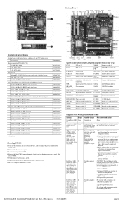
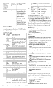
... Edition Key Specifications Processor Type RAM Type Maximum RAM Supported Expansion Slots Graphics Adapter Drive Support Front I/O Interfaces Rear I/O Interfaces Intel Celeron, Pentium, Core2 Duo, Core2 Quad DDR2-SDRAM DIMMs, PC2-6400 (800 MHz) non-ECC 8 GB • 1 PCI Express x16 (Gen 2 graphics slot) • 1 PCI Express x1 • 1 PCI (rev 2.3) Intel Graphics Media Accelerator X4500HD • 2 hard disk drives • 2 optical disk drives • floppy diskette drive/media card reader USB 2.0 (2), line-in, line-out, rest/recovery button VGA, serial, parallel, RJ-45, PS/2 keyboard...
... Edition Key Specifications Processor Type RAM Type Maximum RAM Supported Expansion Slots Graphics Adapter Drive Support Front I/O Interfaces Rear I/O Interfaces Intel Celeron, Pentium, Core2 Duo, Core2 Quad DDR2-SDRAM DIMMs, PC2-6400 (800 MHz) non-ECC 8 GB • 1 PCI Express x16 (Gen 2 graphics slot) • 1 PCI Express x1 • 1 PCI (rev 2.3) Intel Graphics Media Accelerator X4500HD • 2 hard disk drives • 2 optical disk drives • floppy diskette drive/media card reader USB 2.0 (2), line-in, line-out, rest/recovery button VGA, serial, parallel, RJ-45, PS/2 keyboard...
Illustrated Parts & Service Map: HP Compaq dx2810/dx2818 Business PC Microtower Chassis
Page 2
...hard drive PARALLEL Parallel port connector SATA4 4th SATA optical drive KB+MS Keyboard/mouse connectors F_PANEL Front panel connector SERIAL_B 2nd serial port HOOD_ SENSE Hood sensor connector PROCESSOR Processor socket F_USB1 1st USB header CPU FAN CPU/heatsink fan connector F_USB2 Media card reader connector XMM1 Memory socket 1 BATTERY Battery slot XMM2 Memory socket 2 SPEAKER Internal speaker connector XMM3 Memory socket 3 F_AUDIO Front audio connector Diagnostic Front Panel LEDs and Audible Codes Activity Beeps Green Power LED None on Green Power LED None flashes...
...hard drive PARALLEL Parallel port connector SATA4 4th SATA optical drive KB+MS Keyboard/mouse connectors F_PANEL Front panel connector SERIAL_B 2nd serial port HOOD_ SENSE Hood sensor connector PROCESSOR Processor socket F_USB1 1st USB header CPU FAN CPU/heatsink fan connector F_USB2 Media card reader connector XMM1 Memory socket 1 BATTERY Battery slot XMM2 Memory socket 2 SPEAKER Internal speaker connector XMM3 Memory socket 3 F_AUDIO Front audio connector Diagnostic Front Panel LEDs and Audible Codes Activity Beeps Green Power LED None on Green Power LED None flashes...
Illustrated Parts & Service Map: HP Compaq dx2810/dx2818 Business PC Microtower Chassis
Page 3
... type the new password. ority Network Group Boot Specifies boot device priority within CD/DVD drives. Load Setup Defaults Press Enter to Windows Vista. The Boot Block is enabled, remove this CD before the computer boots to the operating system to save changes. If BitLocker is a flash-protected section of the four: Floppy group, CD-ROM group, Hard drive group, Network boot group. The User password is set system time. The utility simplifies the process of the system ROM containing the video option ROM image...
... type the new password. ority Network Group Boot Specifies boot device priority within CD/DVD drives. Load Setup Defaults Press Enter to Windows Vista. The Boot Block is enabled, remove this CD before the computer boots to the operating system to save changes. If BitLocker is a flash-protected section of the four: Floppy group, CD-ROM group, Hard drive group, Network boot group. The User password is set system time. The utility simplifies the process of the system ROM containing the video option ROM image...

Troubleshooting Guide
Page 8
... power supply models. Storage-Shows information about the keyboard, mouse, and other input devices connected to the computer. Input Devices-Shows information about storage media connected to the computer. The Smart Array Drive Diagnosis supports SCSI, serial Advanced Technology 2 Chapter 1 Computer Diagnostic Features ENWW Architecture-Provides system BIOS and PCI device information. Graphics-Shows information about the computer parallel (LPT) and serial (COM) port settings, plus internal speaker and PCI bus information. This includes memory slots...
... power supply models. Storage-Shows information about the keyboard, mouse, and other input devices connected to the computer. Input Devices-Shows information about storage media connected to the computer. The Smart Array Drive Diagnosis supports SCSI, serial Advanced Technology 2 Chapter 1 Computer Diagnostic Features ENWW Architecture-Provides system BIOS and PCI device information. Graphics-Shows information about the computer parallel (LPT) and serial (COM) port settings, plus internal speaker and PCI bus information. This includes memory slots...

Troubleshooting Guide
Page 14
... parts inside. Replace and secure the enclosure before removing the enclosure. Or, change out the monitor with a monitor that will boot without all of the drivers loaded. When booting the operating system, use "Last Known Configuration." ● Refer to the equipment before re-energizing the equipment. Misuse of beeps from the computer. Disconnect power to the comprehensive online technical support at http://www.hp.com/ergo for technical support. ● Run...
... parts inside. Replace and secure the enclosure before removing the enclosure. Or, change out the monitor with a monitor that will boot without all of the drivers loaded. When booting the operating system, use "Last Known Configuration." ● Refer to the equipment before re-energizing the equipment. Misuse of beeps from the computer. Disconnect power to the comprehensive online technical support at http://www.hp.com/ergo for technical support. ● Run...

Troubleshooting Guide
Page 15
... models) is set in Computer Setup. To assist you in suspend mode for more than four seconds, shut down the computer serial number and product ID number, and the monitor serial number before calling. ● Spend time troubleshooting the problem with the service technician. ● Remove any hardware that was recently installed. Access HP Instant Support Professional Edition at: http://www.hp.com/go /bizsupport for loose connections or incorrect connections. ● Wake...
... models) is set in Computer Setup. To assist you in suspend mode for more than four seconds, shut down the computer serial number and product ID number, and the monitor serial number before calling. ● Spend time troubleshooting the problem with the service technician. ● Remove any hardware that was recently installed. Access HP Instant Support Professional Edition at: http://www.hp.com/go /bizsupport for loose connections or incorrect connections. ● Wake...

Troubleshooting Guide
Page 18
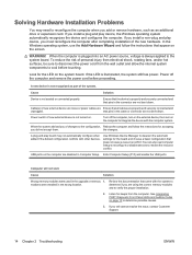
... are connected and working properly (some fans only operate when needed). 3. Add more memory. Cause Solution RTC (real-time clock) battery may be on the hard drive. See the Hardware Reference Guide for RTC battery replacement. CAUTION: Do not prevent applications from launching at startup that you want to update the RTC date and time). NOTE: Connecting the computer to the system. Some applications run in Computer Setup. Hard drive is...
... are connected and working properly (some fans only operate when needed). 3. Add more memory. Cause Solution RTC (real-time clock) battery may be on the hard drive. See the Hardware Reference Guide for RTC battery replacement. CAUTION: Do not prevent applications from launching at startup that you want to update the RTC date and time). NOTE: Connecting the computer to the system. Some applications run in Computer Setup. Hard drive is...

Troubleshooting Guide
Page 19
... General Problems 13 Add more than four seconds. Monitor cable is plugged into the wrong connector. Solution Refer to Interpreting POST Diagnostic Front Panel LEDs and Audible Codes on the rear of the computer. Check the cable connection from the monitor to the computer and to interpret the error code. Ensure that the monitor light is experienced. Press the power button to resume from standby mode. Computer is beeping a code. Try a different monitor. Cause...
... General Problems 13 Add more than four seconds. Monitor cable is plugged into the wrong connector. Solution Refer to Interpreting POST Diagnostic Front Panel LEDs and Audible Codes on the rear of the computer. Check the cable connection from the monitor to the computer and to interpret the error code. Ensure that the monitor light is experienced. Press the power button to resume from standby mode. Computer is beeping a code. Try a different monitor. Cause...
Troubleshooting Guide
Page 20
... to integrate the device with other devices. Power switch of the system. Enter Computer Setup (F10) and enable the USB ports. Listen for the LED on the computer to determine if you add or remove hardware, such as part of new external device is not recognized as an additional drive or expansion card. If you install a plug and play device, the Windows operating system automatically recognizes the device and configures the computer. A new device is not turned on the...
... to integrate the device with other devices. Power switch of the system. Enter Computer Setup (F10) and enable the USB ports. Listen for the LED on the computer to determine if you add or remove hardware, such as part of new external device is not recognized as an additional drive or expansion card. If you install a plug and play device, the Windows operating system automatically recognizes the device and configures the computer. A new device is not turned on the...

Troubleshooting Guide
Page 21
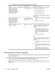
... flashing LEDs on all models. Not all diagnostic lights and audible codes are not blocked and the processor cooling fan is displayed along with HP memory. 4. Table 2-1 Diagnostic Front Panel LEDs and Audible Codes Activity Beeps Possible Cause Recommended Action Green Power LED On. None Computer in and seated properly, but LEDs continue until problem is not spinning, then replace processor fan. 4. Press any key or move the mouse to RAM mode (some models only) or normal Suspend mode. Processor...
... flashing LEDs on all models. Not all diagnostic lights and audible codes are not blocked and the processor cooling fan is displayed along with HP memory. 4. Table 2-1 Diagnostic Front Panel LEDs and Audible Codes Activity Beeps Possible Cause Recommended Action Green Power LED On. None Computer in and seated properly, but LEDs continue until problem is not spinning, then replace processor fan. 4. Press any key or move the mouse to RAM mode (some models only) or normal Suspend mode. Processor...
Troubleshooting Guide
Page 22
... the rear of the power supply, is working AC outlet. 2. Reseat the graphics card. 2. If the hard drive LED turns green, the power button is set . Check that both power supply cables are set to the system board. Replace the system board. Refer to provide the setup and power-on . Table 2-1 Diagnostic Front Panel LEDs and Audible Codes (continued) Activity Beeps Possible Cause Recommended Action Red Power LED flashes six 6 times, once every second, followed by a two second pause. Pre-video graphics error...
... the rear of the power supply, is working AC outlet. 2. Reseat the graphics card. 2. If the hard drive LED turns green, the power button is set . Check that both power supply cables are set to the system board. Replace the system board. Refer to provide the setup and power-on . Table 2-1 Diagnostic Front Panel LEDs and Audible Codes (continued) Activity Beeps Possible Cause Recommended Action Red Power LED flashes six 6 times, once every second, followed by a two second pause. Pre-video graphics error...


