dx2290 Microtower - HP PC
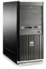
dx2290 Microtower
Related Manual Pages


Similar Questions

How To Create Partition In Hp Pro 3330 Microtower Windows 7 Pc
how to create partition in HP Pro 3330 Microtower windows 7 pc
how to create partition in HP Pro 3330 Microtower windows 7 pc
(Posted by jaswindertoura10 10 years ago)

I How Can I Reset Bios Password On Hp Compaq Dx7300 Microtower
(Posted by 74125jabu 10 years ago)

How Can I Install Windows Xp Sp 2 In Hp Pro 3330 Microtower
how can i install windows xp sp 2 in hp pro 3330 microtower and where can i find the drivers for xp
how can i install windows xp sp 2 in hp pro 3330 microtower and where can i find the drivers for xp
(Posted by kamaljugantor 11 years ago)
Related Terms
The following terms were also used when searching for dx2290 Microtower - HP PC:- hp compaq dx2290
- hp compaq dx2290 mt
- hp compaq dx2290 microtower pc
- hp dx2290 mt
- dx2290 driver
- dx2290 drivers
- dx2290 microtower
- dx2290 mt drivers
- hp dx2290 drivers
- dx2290 mt xp
- hp dx2290 microtower
- hp dx2290 mt xp
- dx2290 lan driver
- dx2290 desktop
- dx2290 mt xp drivers
- hp dx2290 desktop
- hp dx2290 lan driver
- dx2290 driver for windows xp
- dx2290 drivers for xp
- dx2290 specs
- dx2290 xp drivers
- hp desktop dx2290
- hp dx2290 drivers for xp
- hp dx2290 xp drivers
- dx2290 audio driver
- dx2290 drivers xp
- dx2290 price
- dx2290 specification
- compaq dx2290
- compaq dx2290 microtower
- compaq dx2290 microtower pc
- compaq dx2290 mt
- compaq dx2290 mt specification
- compaq dx2290 specification
- dx2200 bios
- dx2200 computer
- dx2200 desktop
- dx2200 drivers
- dx2200 drivers hp
- dx2200 microtower
- dx2200 motherboard
- dx2200 ram
- dx2250 microtower
- dx2290
- dx2290 + drivers
- dx2290 bios
- dx2290 bios drivers
- dx2290 boot
- dx2290 driver download
- dx2290 driver xp
- dx2290 drivers download
- dx2290 drivers for windows xp
- dx2290 drivers for xp download
- dx2290 drivers windows xp
- dx2290 drivers xp download
- dx2290 e2160
- dx2290 ethernet drivers
- dx2290 graphic driver download
- dx2290 hp
- dx2290 lan driver xp
- dx2290 lan drivers
- dx2290 memory
- dx2290 motherboard
- dx2290 mt
- dx2290 mt ethernet driver download
- dx2290 mt lan driver
- dx2290 mt network driver
- dx2290 mt windows xp drivers
- dx2290 mt xp drivers download
- dx2290 pdf
- dx2290 ram model
- dx2290 restore cd
- dx2290 windows 7 drivers
- dx2290 windows xp drivers
- dx2290 xp
- dx2290 xp audio drivers
- hp compaq dx2290 microtower
- hp compaq dx2290 mt specification
- hp compaq dx2290 specification
- hp compaq dx2290 xp drivers
- hp dx2200 bios
- hp dx2200 desktop
- hp dx2200 drivers
- hp dx2200 microtower
- hp dx2200 motherboard
- hp dx2200 ram
- hp dx2250 microtower
- hp dx2290
- hp dx2290 + drivers
- hp dx2290 audio driver
- hp dx2290 driver
- hp dx2290 driver download
- hp dx2290 driver for windows xp
- hp dx2290 drivers download
- hp dx2290 drivers for windows xp
- hp dx2290 drivers for xp download
- hp dx2290 drivers windows xp
- hp dx2290 drivers xp
- hp dx2290 drivers xp download
- hp dx2290 ethernet drivers
- hp dx2290 graphic driver download
- hp dx2290 mt drivers
- hp dx2290 mt lan driver
- hp dx2290 mt network driver
- hp dx2290 mt windows xp drivers
- hp dx2290 mt xp drivers
- hp dx2290 pc
- hp dx2290 pdf
- hp dx2290 price
- hp dx2290 ram model
- hp dx2290 restore cd
- hp dx2290 specification
- hp dx2290 specs
- hp dx2290 windows 7 drivers
- hp dx2290 xp
- hp dx2290mt