HP LaserJet M1522 MFP - Software Technical Reference
Page 347
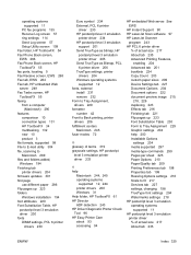
See EWS HP Instant Support 90 HP LaserJet Scan software 97 HP LaserJet Scanner program 243 HP PCL 6 printer driver % of actual size 217 About tab 235 Advanced Printing Features, enabling 204 Advanced tab 201 booklets 224 Copy Count 203 custom paper... supported 12 fonts, external install 231 remove 232 Form to Tray Assignment, drivers 229 formatter number 42 Front to Back printing, printer drivers 206 fulfillment centers Macintosh 245 fuser modes 72 G glossary of terms 319 grayscale settings, HP postscript level 3 emulation printer driver 233 H help 200 Installable Options settings 234 media ...
See EWS HP Instant Support 90 HP LaserJet Scan software 97 HP LaserJet Scanner program 243 HP PCL 6 printer driver % of actual size 217 About tab 235 Advanced Printing Features, enabling 204 Advanced tab 201 booklets 224 Copy Count 203 custom paper... supported 12 fonts, external install 231 remove 232 Form to Tray Assignment, drivers 229 formatter number 42 Front to Back printing, printer drivers 206 fulfillment centers Macintosh 245 fuser modes 72 G glossary of terms 319 grayscale settings, HP postscript level 3 emulation printer driver 233 H help 200 Installable Options settings 234 media ...

HP LaserJet M1522 MFP Series User Guide
Page 229
...recycling of with your waste equipment at www.hp.com/go to www.hp.com/recycle, or contact your local authorities or the Electronics Industries Alliance: www.eiae.org. HP LaserJet M1522 Type Weight Location User-removable Carbon monofluoride lithium 0.8 g On formatter board No For recycling information, you purchased... of your waste equipment by users in private households in a manner that this product must not be obtained by contacting the HP Web site at the time of disposal will help to conserve natural resources and ensure that it is your responsibility to a designated...
...recycling of with your waste equipment at www.hp.com/go to www.hp.com/recycle, or contact your local authorities or the Electronics Industries Alliance: www.eiae.org. HP LaserJet M1522 Type Weight Location User-removable Carbon monofluoride lithium 0.8 g On formatter board No For recycling information, you purchased... of your waste equipment by users in private households in a manner that this product must not be obtained by contacting the HP Web site at the time of disposal will help to conserve natural resources and ensure that it is your responsibility to a designated...

Service Manual
Page 8
... Side covers ...104 Print-cartridge door ...106 Rear cover and fuser cover 107 Front cover ...109 Speaker assembly ...111 Formatter and fax card ...113 Power supply ...114 Scanner support-frame ...118 Laser/scanner assembly 121 Main motor ...125 Fuser ...128 Paper-pickup assembly 132 Drive-gear assembly and drive belt 135 6 Problem...
... Side covers ...104 Print-cartridge door ...106 Rear cover and fuser cover 107 Front cover ...109 Speaker assembly ...111 Formatter and fax card ...113 Power supply ...114 Scanner support-frame ...118 Laser/scanner assembly 121 Main motor ...125 Fuser ...128 Paper-pickup assembly 132 Drive-gear assembly and drive belt 135 6 Problem...
Service Manual
Page 10
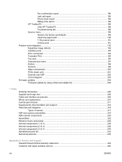
Fax confirmation report 186 Last call report 186 Phone book report 186 Billing-code report 188 HP ToolboxFX ...188 View HP ToolboxFX 188 Troubleshooting tab 188 Service menu ...189 Restore the factory-set defaults 189 Clean the paper path 190 T.30 protocol trace ...191 Archive print ...191 Problem-solve diagrams ...192 Repetitive image defects 192 Interface ports ...193 ECU connectors ...194 Formatter PCA ...195 Fax card ...196...
Fax confirmation report 186 Last call report 186 Phone book report 186 Billing-code report 188 HP ToolboxFX ...188 View HP ToolboxFX 188 Troubleshooting tab 188 Service menu ...189 Restore the factory-set defaults 189 Clean the paper path 190 T.30 protocol trace ...191 Archive print ...191 Problem-solve diagrams ...192 Repetitive image defects 192 Interface ports ...193 ECU connectors ...194 Formatter PCA ...195 Fax card ...196...
Service Manual
Page 13
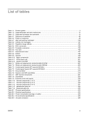
...warning messages ...140 Table 6-2 Critical error messages ...147 Table 6-3 Repetitive image defects ...192 Table 6-4 ECU connectors ...194 Table 6-5 Formatter connectors ...195 Table 6-6 Fax card ...196 Table 6-7 Solenoid and motor ...197 Table 6-8 Rollers ...198 Table 6-9 Sensors ...199 ...product bundle CC372A 207 Table 7-2 Whole unit replacement, product bundle CB534A 209 Table 7-3 Control-panel bezels (HP LaserJet M1522n 211 Table 7-4 Control-panel bezels (HP LaserJet M1522nf 212 Table 7-5 Documentation ...214 Table 7-6 Scanner and ADF assemblies ...219 Table 7-7 ADF internal components ...
...warning messages ...140 Table 6-2 Critical error messages ...147 Table 6-3 Repetitive image defects ...192 Table 6-4 ECU connectors ...194 Table 6-5 Formatter connectors ...195 Table 6-6 Fax card ...196 Table 6-7 Solenoid and motor ...197 Table 6-8 Rollers ...198 Table 6-9 Sensors ...199 ...product bundle CC372A 207 Table 7-2 Whole unit replacement, product bundle CB534A 209 Table 7-3 Control-panel bezels (HP LaserJet M1522n 211 Table 7-4 Control-panel bezels (HP LaserJet M1522nf 212 Table 7-5 Documentation ...214 Table 7-6 Scanner and ADF assemblies ...219 Table 7-7 ADF internal components ...

Service Manual
Page 16
... the front cover (3 of 4 110 Remove the front cover (4 of 4 110 Remove the speaker assembly (1 of 2 111 Remove the speaker assembly (2 of 2 111 Remove the formatter ...113 Remove the power supply (1 of 7 114 Remove the power supply (2 of 7 115 Remove the power supply (3 of 7 115 Remove the power supply (4 of 7 116...
... the front cover (3 of 4 110 Remove the front cover (4 of 4 110 Remove the speaker assembly (1 of 2 111 Remove the speaker assembly (2 of 2 111 Remove the formatter ...113 Remove the power supply (1 of 7 114 Remove the power supply (2 of 7 115 Remove the power supply (3 of 7 115 Remove the power supply (4 of 7 116...

Service Manual
Page 17
...Remove the laser/scanner (1 of 7 121 Figure 5-82 Remove the laser/scanner (2 of 7 122 Figure 5-83 Remove the laser/scanner (3 of 7 122 Figure 5-84 Remove the laser/scanner (4 of 7 123 Figure 5-85 Remove the laser/scanner assembly (5 of 7 123 Figure 5-86 Remove the laser/scanner assembly... connection points (right side 180 Figure 6-2 Print-cartridge high-voltage connection points (left side 181 Figure 6-3 ECU connectors ...194 Figure 6-4 Formatter connectors ...195 Figure 6-5 Fax card connectors ...196 Figure 6-6 Solenoid and motor ...197 Figure 6-7 Rollers ...198 Figure 6-8 Sensors ...199...
...Remove the laser/scanner (1 of 7 121 Figure 5-82 Remove the laser/scanner (2 of 7 122 Figure 5-83 Remove the laser/scanner (3 of 7 122 Figure 5-84 Remove the laser/scanner (4 of 7 123 Figure 5-85 Remove the laser/scanner assembly (5 of 7 123 Figure 5-86 Remove the laser/scanner assembly... connection points (right side 180 Figure 6-2 Print-cartridge high-voltage connection points (left side 181 Figure 6-3 ECU connectors ...194 Figure 6-4 Formatter connectors ...195 Figure 6-5 Fax card connectors ...196 Figure 6-6 Solenoid and motor ...197 Figure 6-7 Rollers ...198 Figure 6-8 Sensors ...199...

Service Manual
Page 66
clears drive potential from the formatter or the power is turned on 48 Chapter 4 Operational theory ENWW Table 4-1 Sequence of operation Name Timing Purpose WAIT From power-on until the pickup ... for the base unit Operational sequences are controlled by the microprocessor and the DC controller. The following systems are discussed: ● Engine control system ● Laser/scanner system ● Pickup/feed/delivery system ● Image-formation system Figure 4-1 System block diagram Sequence of the WAIT (power-on) period. STBY (standby) From...
clears drive potential from the formatter or the power is turned on 48 Chapter 4 Operational theory ENWW Table 4-1 Sequence of operation Name Timing Purpose WAIT From power-on until the pickup ... for the base unit Operational sequences are controlled by the microprocessor and the DC controller. The following systems are discussed: ● Engine control system ● Laser/scanner system ● Pickup/feed/delivery system ● Image-formation system Figure 4-1 System block diagram Sequence of the WAIT (power-on) period. STBY (standby) From...

Service Manual
Page 67
...Check sensors for residual media 5 Main motor initial drive 6 Fuser heater initial drive. The fuser heater reaches a surface temperature of 100o C. 7 Laser/scanner motor initial drive 8 High-voltage control Detect presence of a print cartridge Clean the transfer roller after the primary charging AC bias is turned ...From the end of a print job After LSTR, the product either returns to STBY or, if another print command was sent from the formatter, enters INTR. Table 4-1 Sequence of operation (continued) Name Timing Purpose PRINT From the end of the INTR period until the primary ...
...Check sensors for residual media 5 Main motor initial drive 6 Fuser heater initial drive. The fuser heater reaches a surface temperature of 100o C. 7 Laser/scanner motor initial drive 8 High-voltage control Detect presence of a print cartridge Clean the transfer roller after the primary charging AC bias is turned ...From the end of a print job After LSTR, the product either returns to STBY or, if another print command was sent from the formatter, enters INTR. Table 4-1 Sequence of operation (continued) Name Timing Purpose PRINT From the end of the INTR period until the primary ...

Service Manual
Page 68
...raster line. Scanner and ADF functions and operation The following sections describe how the document scanner and the automatic document feeder (ADF) function. The formatter then handles the image data, outputting it as scanner output. Each pixel has 8 bits for each of the three colors (256 gray scale levels... next raster line. The resolution of the image data collected depends on the task being used , the scanner module advances to the formatter. This advancing and collection process continues to collect optical information about the document and transform that into an image file.
...raster line. Scanner and ADF functions and operation The following sections describe how the document scanner and the automatic document feeder (ADF) function. The formatter then handles the image data, outputting it as scanner output. Each pixel has 8 bits for each of the three colors (256 gray scale levels... next raster line. The resolution of the image data collected depends on the task being used , the scanner module advances to the formatter. This advancing and collection process continues to collect optical information about the document and transform that into an image file.

Service Manual
Page 73
Engine control system The engine control system coordinates all of the product functions, according to commands sent from the formatter. The engine control system contains the following components: ● Formatter ● High-voltage PCA Figure 4-5 Engine control system ENWW Engine control system 55 It drives the laser/scanner system, the image-formation system, and the pickup/feed/ delivery system.
Engine control system The engine control system coordinates all of the product functions, according to commands sent from the formatter. The engine control system contains the following components: ● Formatter ● High-voltage PCA Figure 4-5 Engine control system ENWW Engine control system 55 It drives the laser/scanner system, the image-formation system, and the pickup/feed/ delivery system.

Service Manual
Page 74
Figure 4-6 Engine-control-system circuit diagram ECU PCA Fuser AC input Fan Transfer roller Pressure roller Print cartridge Fuser control circuit Low-voltage power supply circuit Fan motor drive circuit IC502 Reset IC High-voltage power supply circuit Memory tag circuit IC201 CPU Memory tag Formatter Main motor Solenoids Sensors Option Laser/scanner motor Laser driver BD sensor 56 Chapter 4 Operational theory ENWW
Figure 4-6 Engine-control-system circuit diagram ECU PCA Fuser AC input Fan Transfer roller Pressure roller Print cartridge Fuser control circuit Low-voltage power supply circuit Fan motor drive circuit IC502 Reset IC High-voltage power supply circuit Memory tag circuit IC201 CPU Memory tag Formatter Main motor Solenoids Sensors Option Laser/scanner motor Laser driver BD sensor 56 Chapter 4 Operational theory ENWW

Service Manual
Page 75
Figure 4-7 Laser/scanner system ENWW Laser/scanner system 57 Laser/scanner system The laser/scanner system receives video signals from the formatter, and converts the signals into latent images on the photosensitive drum.
Figure 4-7 Laser/scanner system ENWW Laser/scanner system 57 Laser/scanner system The laser/scanner system receives video signals from the formatter, and converts the signals into latent images on the photosensitive drum.

Service Manual
Page 76
... SL1 Separation pad Multi-purpose tray 58 Chapter 4 Operational theory ENWW If media does not reach or pass each sensor within a specified time period, the formatter determines that a jam has occurred. A motor and solenoid are identified in Figure 4-8 Pickup/feed/delivery system on page 58: ● M1, main motor ● SL1...
... SL1 Separation pad Multi-purpose tray 58 Chapter 4 Operational theory ENWW If media does not reach or pass each sensor within a specified time period, the formatter determines that a jam has occurred. A motor and solenoid are identified in Figure 4-8 Pickup/feed/delivery system on page 58: ● M1, main motor ● SL1...
Service Manual
Page 83
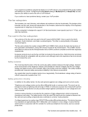
... between the fax card and surrounding components also contribute to Medium(V.17) or Slow(V.29) can be transient in the HP LaserJet M1522 MFP. Telephone over -voltage and overcurrent events. Configuring the Fax Speed setting to common mode protection. The fax card contains the...Asian countries/regions. The fax card protection circuitry provides margin against over-voltage and over a VoIP network. The fax subsystem The formatter, fax card, firmware, and software all of the regulatory requirements for fax transmissions. Safety isolation The most important function of the...
... between the fax card and surrounding components also contribute to Medium(V.17) or Slow(V.29) can be transient in the HP LaserJet M1522 MFP. Telephone over -voltage and overcurrent events. Configuring the Fax Speed setting to common mode protection. The fax card contains the...Asian countries/regions. The fax card protection circuitry provides margin against over-voltage and over a VoIP network. The fax subsystem The formatter, fax card, firmware, and software all of the regulatory requirements for fax transmissions. Safety isolation The most important function of the...

Service Manual
Page 84
... it detects a fax tone or the user causes it recognizes as fax calls. During eavesdropping, the receive circuit is enabled but current exists in the formatter using the high-speed serial interface. The product does not take control of calls that an active device (telephone, modem, or answering machine) is off...
... it detects a fax tone or the user causes it recognizes as fax calls. During eavesdropping, the receive circuit is enabled but current exists in the formatter using the high-speed serial interface. The product does not take control of calls that an active device (telephone, modem, or answering machine) is off...

Service Manual
Page 92
... cover and fuser cover Power supply Scanner assembly Print-cartridge door Front cover Scanner support-frame Engine controller unit Laser/scanner assembly Main motor Fuser assembly Pickup assembly Front cover Speaker assembly Formatter and fax card 74 Chapter 5 Removal and replacement ENWW Parts removal order Use the following diagrams to determine which...
... cover and fuser cover Power supply Scanner assembly Print-cartridge door Front cover Scanner support-frame Engine controller unit Laser/scanner assembly Main motor Fuser assembly Pickup assembly Front cover Speaker assembly Formatter and fax card 74 Chapter 5 Removal and replacement ENWW Parts removal order Use the following diagrams to determine which...

Service Manual
Page 110
Figure 5-34 Remove the scanner assembly (6 of 10) 7. 6. J2, J33, J4, and J27) on the formatter, and then remove the harnesses and FFC from the retainers. Remove one screw (callout 4) to release the scanner assembly, and then raise the assembly until ...
Figure 5-34 Remove the scanner assembly (6 of 10) 7. 6. J2, J33, J4, and J27) on the formatter, and then remove the harnesses and FFC from the retainers. Remove one screw (callout 4) to release the scanner assembly, and then raise the assembly until ...

Service Manual
Page 131
...the removal or reinstallation process. You do not need to remove the scanner assembly to the formatter. Disconnect all FFCs and wire-harness from the formatter PCA (callout 1). Figure 5-68 Remove the formatter 1 2 ENWW Product base 113 If the scanner assembly is shown removed in this procedure.... Remove five screws from the formatter and fax card. NOTE: The scanner assembly is installed, there will be additional FFCs and wire-harness connected to remove the formatter and fax card. 3. Remove three screws (callout 2) from the fax...
...the removal or reinstallation process. You do not need to remove the scanner assembly to the formatter. Disconnect all FFCs and wire-harness from the formatter PCA (callout 1). Figure 5-68 Remove the formatter 1 2 ENWW Product base 113 If the scanner assembly is shown removed in this procedure.... Remove five screws from the formatter and fax card. NOTE: The scanner assembly is installed, there will be additional FFCs and wire-harness connected to remove the formatter and fax card. 3. Remove three screws (callout 2) from the fax...

Service Manual
Page 132
See Front cover on page 107. ● Front cover. See Rear cover and fuser cover on page 109. ● Speaker assembly. Disconnect one spade connector (callout 1) and remove three screws (callout 2). See Speaker assembly on page 113. 2. See Formatter and fax card on page 111. ● Formatter and fax card. Power supply 1. Figure 5-69 Remove the power supply (1 of 7) 1 2 114 Chapter 5 Removal and replacement ENWW Remove the following assemblies: ● Right and left covers. See Side covers on page 104. ● Rear cover and fuser cover.
See Front cover on page 107. ● Front cover. See Rear cover and fuser cover on page 109. ● Speaker assembly. Disconnect one spade connector (callout 1) and remove three screws (callout 2). See Speaker assembly on page 113. 2. See Formatter and fax card on page 111. ● Formatter and fax card. Power supply 1. Figure 5-69 Remove the power supply (1 of 7) 1 2 114 Chapter 5 Removal and replacement ENWW Remove the following assemblies: ● Right and left covers. See Side covers on page 104. ● Rear cover and fuser cover.


