Service Guide
Page 4
...components 2-1 Lights 2-2 Buttons and speakers 2-3 Keys 2-4 TouchPad 2-5 Front components 2-6 Rear components 2-6 Left-side components 2-7 Right-side components 2-7 Bottom components 2-8 3 Illustrated parts catalog Serial number location 3-1 Computer major components 3-2 Display assembly components 3-9 Plastics Kit 3-11 Mass storage devices 3-12 Miscellaneous parts 3-13 Sequential part number listing 3-14 4 Removal and replacement procedures Preliminary replacement requirements 4-1 Tools required 4-1 Service considerations 4-1 Grounding guidelines 4-2 Unknown user password...
...components 2-1 Lights 2-2 Buttons and speakers 2-3 Keys 2-4 TouchPad 2-5 Front components 2-6 Rear components 2-6 Left-side components 2-7 Right-side components 2-7 Bottom components 2-8 3 Illustrated parts catalog Serial number location 3-1 Computer major components 3-2 Display assembly components 3-9 Plastics Kit 3-11 Mass storage devices 3-12 Miscellaneous parts 3-13 Sequential part number listing 3-14 4 Removal and replacement procedures Preliminary replacement requirements 4-1 Tools required 4-1 Service considerations 4-1 Grounding guidelines 4-2 Unknown user password...
Service Guide
Page 5
...Top cover 4-30 TouchPad on/off button board and board bracket 4-32 Audio board 4-34 Bluetooth module 4-35 Speakers 4-36 USB board 4-37 System board 4-38 Fan/heat sink assembly 4-41 Processor 4-44 Power connector cable 4-46 5 Setup Utility Starting the Setup Utility 5-1 Changing the language of the Setup Utility 5-1 Navigating and selecting in the Setup Utility 5-2 Displaying system information 5-2 Restoring default settings in the Setup Utility 5-2 Exiting the Setup Utility 5-3 Setup Utility menus 5-3 Main menu 5-3 Security menu 5-3 System Configuration menu 5-4 Diagnostics...
...Top cover 4-30 TouchPad on/off button board and board bracket 4-32 Audio board 4-34 Bluetooth module 4-35 Speakers 4-36 USB board 4-37 System board 4-38 Fan/heat sink assembly 4-41 Processor 4-44 Power connector cable 4-46 5 Setup Utility Starting the Setup Utility 5-1 Changing the language of the Setup Utility 5-1 Navigating and selecting in the Setup Utility 5-2 Displaying system information 5-2 Restoring default settings in the Setup Utility 5-2 Exiting the Setup Utility 5-3 Setup Utility menus 5-3 Main menu 5-3 Security menu 5-3 System Configuration menu 5-4 Diagnostics...
Service Guide
Page 10
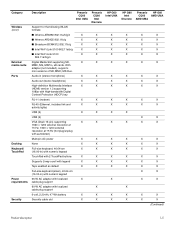
... and 512-MB memory) Webcam VGA camera, 640 x 480 resolution, X 22.5 frames per second, fixed angle with activity light Microphone Intregated single analog microphone X Audio High-definition audio supports X Microsoft premium requirements Modem 56K V.92 1.5-inch data/fax modem X Computer models not equipped with X a modem will have a cover on the RJ-11 jack opening Supports all 9.5-mm, 6.35-cm X (2.50-in) SATA hard drives Customer accessible X Single hard drive configurations: 120-GB...
... and 512-MB memory) Webcam VGA camera, 640 x 480 resolution, X 22.5 frames per second, fixed angle with activity light Microphone Intregated single analog microphone X Audio High-definition audio supports X Microsoft premium requirements Modem 56K V.92 1.5-inch data/fax modem X Computer models not equipped with X a modem will have a cover on the RJ-11 jack opening Supports all 9.5-mm, 6.35-cm X (2.50-in) SATA hard drives Customer accessible X Single hard drive configurations: 120-GB...
Service Guide
Page 11
... power X None X Full-size keyboard, 40.64-cm X (16.00-in) with numeric keypad TouchPad with 2 TouchPad buttons X Supports 2-way scroll with legend X Taps enabled as default X Full-size keyboard (silver), 40.64-cm (16.00-in) with numeric keypad 65-W AC adapter with localized X cable plug support 90-W AC adapter with localized cable plug support 6-cell, 2.20-Ah, 47-Wh battery X Security cable slot X Presario CQ60 Intel Discrete HP G60...
... power X None X Full-size keyboard, 40.64-cm X (16.00-in) with numeric keypad TouchPad with 2 TouchPad buttons X Supports 2-way scroll with legend X Taps enabled as default X Full-size keyboard (silver), 40.64-cm (16.00-in) with numeric keypad 65-W AC adapter with localized X cable plug support 90-W AC adapter with localized cable plug support 6-cell, 2.20-Ah, 47-Wh battery X Security cable slot X Presario CQ60 Intel Discrete HP G60...
Service Guide
Page 14
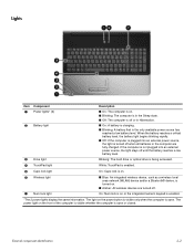
... is plugged into an external power source, the light stays off until the battery reaches a low battery level. Blinking: The hard drive or optical drive is being accessed. 4 TouchPad light White: TouchPad is enabled. 5 Caps lock light On: Caps lock is on. 6 Wireless light 7 Num lock light ■ Blue: An integrated wireless device, such as a wireless local area network (WLAN) device and/or a Bluetooth® device, is turned on. ■ Amber: All wireless devices are fully charged. Lights Item Component 1 Power lights* (2) 2 Battery light 3 Drive light Description ■ On...
... is plugged into an external power source, the light stays off until the battery reaches a low battery level. Blinking: The hard drive or optical drive is being accessed. 4 TouchPad light White: TouchPad is enabled. 5 Caps lock light On: Caps lock is on. 6 Wireless light 7 Num lock light ■ Blue: An integrated wireless device, such as a wireless local area network (WLAN) device and/or a Bluetooth® device, is turned on. ■ Amber: All wireless devices are fully charged. Lights Item Component 1 Power lights* (2) 2 Battery light 3 Drive light Description ■ On...
Service Guide
Page 18
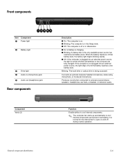
... into an external power source, the light stays off during routine operation. Produces sound when connected to cool internal components and prevent overheating. Blinking: The hard drive or optical drive is being accessed. Connects an optional computer headset microphone, stereo array microphone, or monaural microphone. If the computer is not plugged into an external power source, the light is turned off when all batteries in Hibernation. ■ On: A battery is charging. ■ Blinking: A battery that is...
... into an external power source, the light stays off during routine operation. Produces sound when connected to cool internal components and prevent overheating. Blinking: The hard drive or optical drive is being accessed. Connects an optional computer headset microphone, stereo array microphone, or monaural microphone. If the computer is not plugged into an external power source, the light is turned off when all batteries in Hibernation. ■ On: A battery is charging. ■ Blinking: A battery that is...
Service Guide
Page 19
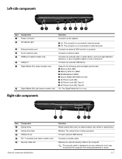
...an optional USB device. Blinking: The optical drive is being mishandled or stolen. 2-7 Left-side components Item Component 1 Power connector 2 AC adapter light 3 External monitor port 4 RJ-45 (network) jack 5 HDMI port (select models only) 6 USB port 7 Digital Media Slot (select models only) 8 Digital Media Slot light (select models only) Function Connects an AC adapter. ■ On: The computer is connected to external power. ■ Off: The computer is not connected to optical discs. Supports the following optional digital card formats: ■ Memory Stick (MS) ■ Memory Stick...
...an optional USB device. Blinking: The optical drive is being mishandled or stolen. 2-7 Left-side components Item Component 1 Power connector 2 AC adapter light 3 External monitor port 4 RJ-45 (network) jack 5 HDMI port (select models only) 6 USB port 7 Digital Media Slot (select models only) 8 Digital Media Slot light (select models only) Function Connects an AC adapter. ■ On: The computer is connected to external power. ■ Off: The computer is not connected to optical discs. Supports the following optional digital card formats: ■ Memory Stick (MS) ■ Memory Stick...
Service Guide
Page 20
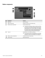
... module compartment 4 Vents (4) 5 Memory module compartment 6 Hard drive bay Function Holds the battery. It is normal for use in the computer by the governmental agency that regulates wireless devices in your country or region. Contains the memory module slots. Holds the hard drive. Holds the WLAN module. Ä To prevent an unresponsive system, replace the wireless module with only a wireless module authorized for the internal fan to cycle on and off during routine operation...
... module compartment 4 Vents (4) 5 Memory module compartment 6 Hard drive bay Function Holds the battery. It is normal for use in the computer by the governmental agency that regulates wireless devices in your country or region. Contains the memory module slots. Holds the hard drive. Holds the WLAN module. Ä To prevent an unresponsive system, replace the wireless module with only a wireless module authorized for the internal fan to cycle on and off during routine operation...
Service Guide
Page 21
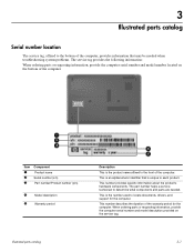
This is the number used to locate documents, drivers, and support for the computer. This number provides specific information about the product's hardware components. Item 1 2 3 Component Product name Serial number (s/n) Part number/Product number (p/n) 4 Model description 5 Warranty period Description This is the product name affixed to the front of the computer. This number describes the duration of the warranty period for the computer. This is an...
This is the number used to locate documents, drivers, and support for the computer. This number provides specific information about the product's hardware components. Item 1 2 3 Component Product name Serial number (s/n) Part number/Product number (p/n) 4 Model description 5 Warranty period Description This is the product name affixed to the front of the computer. This number describes the duration of the warranty period for the computer. This is an...
Service Guide
Page 38
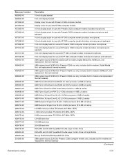
...) 1-GB memory module (PC2-5300, 667-MHz, DDR) 2-GB memory module (PC2-5300, 667-MHz, DDR) 120-GB hard drive 160-GB hard drive 250-GB hard drive DVD±RW and CD-RW SuperMulti Double-Layer Combo Drive DVD±RW and CD-RW SuperMulti Double-Layer Combo Drive with HP G60 computer models (includes microphone and webcam) UMA system board, NVIDIA (includes built-in modem, Digital Media Slot, HDMI port, and replacement thermal...
...) 1-GB memory module (PC2-5300, 667-MHz, DDR) 2-GB memory module (PC2-5300, 667-MHz, DDR) 120-GB hard drive 160-GB hard drive 250-GB hard drive DVD±RW and CD-RW SuperMulti Double-Layer Combo Drive DVD±RW and CD-RW SuperMulti Double-Layer Combo Drive with HP G60 computer models (includes microphone and webcam) UMA system board, NVIDIA (includes built-in modem, Digital Media Slot, HDMI port, and replacement thermal...
Service Guide
Page 44
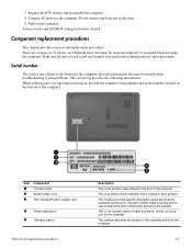
.... 8. Make special note of the warranty period for the computer. This is the product name affixed to each screw and standoff size and location during removal and replacement. All passwords and all CMOS settings have been cleared. Item 1 2 3 Component Product name Serial number (s/n) Part number/Product number (p/n) 4 Model description 5 Warranty period Removal and replacement procedures Description This is the number used to the computer. Connect AC power to locate documents, drivers, and support...
.... 8. Make special note of the warranty period for the computer. This is the product name affixed to each screw and standoff size and location during removal and replacement. All passwords and all CMOS settings have been cleared. Item 1 2 3 Component Product name Serial number (s/n) Part number/Product number (p/n) 4 Model description 5 Warranty period Removal and replacement procedures Description This is the number used to the computer. Connect AC power to locate documents, drivers, and support...
Service Guide
Page 51
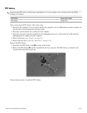
... all passwords and CMOS settings to the system board with double-sided tape. Remove the battery (see "Hard drive" on page 4-7). 5. RTC battery ✎ Removing the RTC battery and leaving it down the computer. The RTC battery is off or in Hibernation, turn the computer on, and then shut it uninstalled for 5 or more minutes causes all external devices connected to install the RTC battery. Description RTC battery Spare part number...
... all passwords and CMOS settings to the system board with double-sided tape. Remove the battery (see "Hard drive" on page 4-7). 5. RTC battery ✎ Removing the RTC battery and leaving it down the computer. The RTC battery is off or in Hibernation, turn the computer on, and then shut it uninstalled for 5 or more minutes causes all external devices connected to install the RTC battery. Description RTC battery Spare part number...
Service Guide
Page 66
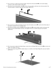
... part number 486558-001. The display inverter is necessary to replace the display inverter, release the display inverter 1, located at the bottom edge of the display assembly, from the display enclosure as far from its mounting clips. 13. Disconnect the display panel cable 2 and the back light cable 3 from the display inverter, and remove the display inverter from the webcam module, and remove the webcam module. If it is necessary to replace the display...
... part number 486558-001. The display inverter is necessary to replace the display inverter, release the display inverter 1, located at the bottom edge of the display assembly, from the display enclosure as far from its mounting clips. 13. Disconnect the display panel cable 2 and the back light cable 3 from the display inverter, and remove the display inverter from the webcam module, and remove the webcam module. If it is necessary to replace the display...
Service Guide
Page 74
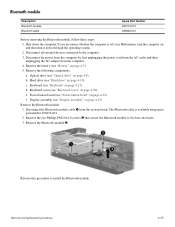
... the operating system. 2. Keyboard (see "Hard drive" on , and then shut it down the computer. Reverse this procedure to the computer. 3. If you are unsure whether the computer is available using spare part number 496836-001. 2. Hard drive (see "Keyboard" on page 4-22) f. Keyboard cover (see "Power button board" on page 4-17) d. Disconnect all external devices connected to install the Bluetooth module. Remove the following components: a. Disconnect the Bluetooth module cable 1 from the computer. 4. Power button board (see "Keyboard cover...
... the operating system. 2. Keyboard (see "Hard drive" on , and then shut it down the computer. Reverse this procedure to the computer. 3. If you are unsure whether the computer is available using spare part number 496836-001. 2. Hard drive (see "Keyboard" on page 4-22) f. Keyboard cover (see "Power button board" on page 4-17) d. Disconnect all external devices connected to install the Bluetooth module. Remove the following components: a. Disconnect the Bluetooth module cable 1 from the computer. 4. Power button board (see "Keyboard cover...
Service Guide
Page 82
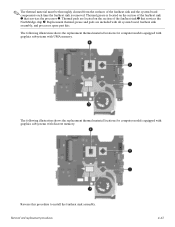
Reverse this procedure to install the fan/heat sink assembly. Replacement thermal grease and pads are located on the section of the fan/heat sink 1 that services the Northbridge chip 4. The following illustration shows the replacement thermal material locations for computer models equipped with graphics subsystems with all system board, fan/heat sink assembly, and processor spare part kits. Removal and replacement procedures 4-43 Thermal grease...
Reverse this procedure to install the fan/heat sink assembly. Replacement thermal grease and pads are located on the section of the fan/heat sink 1 that services the Northbridge chip 4. The following illustration shows the replacement thermal material locations for computer models equipped with graphics subsystems with all system board, fan/heat sink assembly, and processor spare part kits. Removal and replacement procedures 4-43 Thermal grease...
Service Guide
Page 87
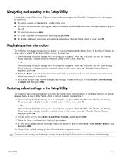
... Changes, and then press enter. or - Use the arrow keys to the menu display, press esc. ■ To display additional navigation and selection information while the Setup Utility is not open , begin at step 2. 1. If the Setup Utility is open, press f1. While the "Press the ESC key from Startup Menu" message is not Windows based, it does not support the TouchPad. When the Startup Menu is displayed, press f10. 2. Restoring default settings in the Setup Utility...
... Changes, and then press enter. or - Use the arrow keys to the menu display, press esc. ■ To display additional navigation and selection information while the Setup Utility is not open , begin at step 2. 1. If the Setup Utility is open, press f1. While the "Press the ESC key from Startup Menu" message is not Windows based, it does not support the TouchPad. When the Startup Menu is displayed, press f10. 2. Restoring default settings in the Setup Utility...
Service Guide
Page 89
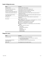
...; Internal Network Adapter boot-Enable/disable boot from Internal Network Adapter. ■ Boot Order-Set the boot order for: ❐ USB Floppy ❐ Internal CD/DVD ROM Drive ❐ Hard drive ❐ USB Diskette on Key ❐ USB Hard drive ❐ Network adapter Diagnostics menu Select Hard Disk Self Test Secondary Hard Disk Self Test (select models only) Memory Test To do this menu option is called the Primary Hard Disk Self Test. When enabled, the computer fan will always be on the hard drive. ✎ On models with two hard drives, this Change the Setup Utility...
...; Internal Network Adapter boot-Enable/disable boot from Internal Network Adapter. ■ Boot Order-Set the boot order for: ❐ USB Floppy ❐ Internal CD/DVD ROM Drive ❐ Hard drive ❐ USB Diskette on Key ❐ USB Hard drive ❐ Network adapter Diagnostics menu Select Hard Disk Self Test Secondary Hard Disk Self Test (select models only) Memory Test To do this menu option is called the Primary Hard Disk Self Test. When enabled, the computer fan will always be on the hard drive. ✎ On models with two hard drives, this Change the Setup Utility...
Service Guide
Page 130
... 2-8 BIOS administrator password 5-3 Bluetooth module removal 4-35 spare part number 4-35 Bluetooth module cable 3-17 removal 4-35 spare part number 3-6, 3-17 Blu-ray disc specifications 6-4 Blu-ray ROM DVD±RW SuperMulti DL Drive product description 1-4 removal 4-9 spare part number 4-8 specifications 6-4 boot options 5-4 boot order 5-4 bottom components 2-8 Index Index built-in device Bluetooth device radio 2-8 modem 1-4 wireless button 2-3 WLAN device radio 2-8 buttons power 2-3 wireless 2-3 C cables, service consideration 4-1 caps lock light 2-2 chipset, product description 1-2 CMOS...
... 2-8 BIOS administrator password 5-3 Bluetooth module removal 4-35 spare part number 4-35 Bluetooth module cable 3-17 removal 4-35 spare part number 3-6, 3-17 Blu-ray disc specifications 6-4 Blu-ray ROM DVD±RW SuperMulti DL Drive product description 1-4 removal 4-9 spare part number 4-8 specifications 6-4 boot options 5-4 boot order 5-4 bottom components 2-8 Index Index built-in device Bluetooth device radio 2-8 modem 1-4 wireless button 2-3 WLAN device radio 2-8 buttons power 2-3 wireless 2-3 C cables, service consideration 4-1 caps lock light 2-2 chipset, product description 1-2 CMOS...
Service Guide
Page 131
... media cards, product description 1-5 external monitor port location 2-7 pin assignments 9-2 F f11 recovery 8-4 factory state, recovering to 8-1 fan removal 4-41 spare part number 3-4, 3-15, 4-41 feet locations 4-6 spare part number 4-6 fn key 2-4 front components 2-6 function keys 2-4 G graphics, product description 1-2, 1-3 grounding equipment 4-4 H hard drive precautions 4-2 product description 1-4 removal 4-10 spare part number 3-6, 3-12, 4-10 specifications 6-2 Index hard drive backup 8-2 hard drive bay 2-8 hard drive bracket, removal 4-11 hard drive cover illustration 3-4, 3-11 removal...
... media cards, product description 1-5 external monitor port location 2-7 pin assignments 9-2 F f11 recovery 8-4 factory state, recovering to 8-1 fan removal 4-41 spare part number 3-4, 3-15, 4-41 feet locations 4-6 spare part number 4-6 fn key 2-4 front components 2-6 function keys 2-4 G graphics, product description 1-2, 1-3 grounding equipment 4-4 H hard drive precautions 4-2 product description 1-4 removal 4-10 spare part number 3-6, 3-12, 4-10 specifications 6-2 Index hard drive backup 8-2 hard drive bay 2-8 hard drive bracket, removal 4-11 hard drive cover illustration 3-4, 3-11 removal...
Service Guide
Page 133
... 8-3 recovery partition 8-4 removal/replacement preliminaries 4-1 procedures 4-5 restore points 8-3 restoring factory settings 5-2 right-side components 2-7 RJ-11 (modem) jack location 2-7 pin assignments 9-4 RJ-45 (network) jack location 2-7 pin assignments 9-4 RTC battery removal 4-12 spare part number 3-6, 3-19, 4-12 Rubber Feet Kit, spare part number 3-6, 3-15 S scheduling backups 8-2 Screw Kit contents 3-13 spare part number 3-10, 3-15, 7-1 screw listing 7-1 security cable slot 2-7 Security menu BIOS administrator password 5-3 Power-On password 5-3 security, product description 1-5 serial...
... 8-3 recovery partition 8-4 removal/replacement preliminaries 4-1 procedures 4-5 restore points 8-3 restoring factory settings 5-2 right-side components 2-7 RJ-11 (modem) jack location 2-7 pin assignments 9-4 RJ-45 (network) jack location 2-7 pin assignments 9-4 RTC battery removal 4-12 spare part number 3-6, 3-19, 4-12 Rubber Feet Kit, spare part number 3-6, 3-15 S scheduling backups 8-2 Screw Kit contents 3-13 spare part number 3-10, 3-15, 7-1 screw listing 7-1 security cable slot 2-7 Security menu BIOS administrator password 5-3 Power-On password 5-3 security, product description 1-5 serial...


