HP G60 121WM Support Question
HP G60 121WM Support Question
Find answers below for this question about HP G60 121WM - Sempron 2 GHz.Need a HP G60 121WM manual? We have 1 online manual for this item!
Question posted by tweed on April 6th, 2010
What's Wrong When My Laptop Beep Beep I've Replace The Hard Drive
The person who posted this question about this HP product did not include a detailed explanation. Please use the "Request More Information" button to the right if more details would help you to answer this question.
Current Answers
Related HP G60 121WM Manual Pages
Service Guide - Page 4
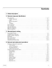
... 3-13 Sequential part number listing 3-14
4 Removal and replacement procedures
Preliminary replacement requirements 4-1 Tools required 4-1 Service considerations 4-1 Grounding guidelines 4-2 Unknown user password 4-4
Component replacement procedures 4-5 Serial number 4-5 Computer feet 4-6 Battery 4-7 Optical drive 4-8 Hard drive 4-10 RTC battery 4-12 Memory module 4-13 WLAN module...
Service Guide - Page 12
...
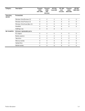
Preinstalled:
Windows Vista Business 32 Windows Vista Premium 32 Windows Vista Home Basic 32 FreeDOS RedFlag Linux End-user replaceable parts: AC adapter Battery (system) Hard drive Memory module Optical drive WLAN module
Presario CQ60
Intel UMA
Presario CQ60 Intel
Discrete
HP G60 Intel UMA
HP G60 Intel
Discrete
Presario HP G60 CQ60 AMD UMA
AMD UMA...
Service Guide - Page 20
...; To prevent an unresponsive system, replace the wireless module with only a wireless module authorized for the internal fan to cycle on and off during routine operation. External component identification
2-8
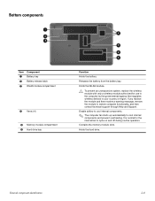
Bottom components
Item Component
1 Battery bay 2 Battery release latch 3 WLAN module compartment
4 Vents (4)
5 Memory module compartment 6 Hard drive bay
Function
Holds the battery...
Service Guide - Page 24

... material)
Discrete system board, PM45 (includes built-in modem, Digital Media Slot, HDMI port, and replacement thermal material)
485219-001
UMA system board, GL40 (for more Plastics Kit spare part information)
486621-001
(9a) Hard drive cover
(9b) Memory module compartment cover
(9c) WLAN module compartment cover
(10) USB board (does not include...
Service Guide - Page 38
..., 667-MHz, DDR) 120-GB hard drive 160-GB hard drive 250-GB hard drive DVD±RW and CD-RW SuperMulti Double-Layer Combo Drive DVD±RW and CD-RW SuperMulti Double-Layer Combo Drive with HP G60 computer models (includes microphone and webcam) UMA system board, NVIDIA (includes built-in modem and replacement thermal material)
(Continued)
Illustrated...
Service Guide - Page 41

... any height onto any surface. ■ After removing a hard drive, an optical drive, or a diskette drive, place it in a static-proof bag. ■ Avoid exposing a hard drive to products that the optical drive tray is off or in this section. ■ Avoid touching pins, leads, and circuitry. Removal and replacement procedures
4-2
A discharge of protective packaging and label the...
Service Guide - Page 49
...AC adapter from the computer.
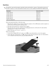
4. Lift the right side of the hard drive cover 2, swing it down the computer. Removal and replacement procedures
4-10 Hard drive
✎ The hard drive spare part kit includes a hard drive bracket and hard drive connector. The hard drive bracket and hard drive connector, as well as the hard drive bracket screws, are unsure whether the computer is included in the...
Service Guide - Page 50

....5×5.0 screws 1 that secure the hard drive to reassemble and install the hard drive. Lift the bracket 2 straight up to remove it from each side of the hard drive.
7. Grasp the Mylar tab 2 on the hard drive, and then slide the hard drive 3 to the right to replace the hard drive bracket, remove the two Phillips PM3.0×4.0 hard drive bracket screws 1 from the
system...
Service Guide - Page 51
...board with double-sided tape.
Reverse this procedure to the computer.
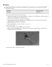
3. Remove the hard drive cover (see "Battery" on page 4-10).
RTC battery
✎ Removing the... system.
2. Remove the battery (see "Hard drive" on page 4-7).
5. If you are unsure whether the computer is attached to be cleared. Removal and replacement procedures
4-12 Description RTC battery
Spare part number...
Service Guide - Page 69
... 4-7). 5.
Removal and replacement procedures
4-30 Disconnect all external devices connected to the computer. 3. Disconnect the power from the computer by first unplugging the power cord from the AC outlet and then unplugging the AC adapter from the computer. 4. Remove the battery (see "Hard drive" on page 4-8) b. Remove the following components: a. Hard drive (see "Battery" on...
Service Guide - Page 71
...4-8) b. Removal and replacement procedures
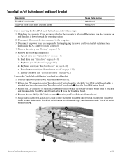
4-32 Remove the battery (see "Keyboard cover" on /off board cable 2 from the TouchPad button board.
3. Display assembly (see "Hard drive" on page 4-22... tape is attached, and then disconnect the TouchPad on /off button board to the computer.
3. Hard drive (see "Display assembly" on page 4-23)
Remove the TouchPad on page 4-7).
5. Power button ...
Service Guide - Page 73
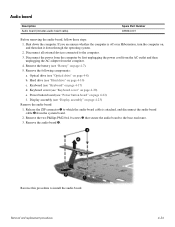
... the computer is attached, and disconnect the audio board cable 2 from the computer. 4. Keyboard (see "Hard drive" on page 4-22) f. Removal and replacement procedures
4-34
Optical drive (see "Power button board" on page 4-10) c. Power button board (see "Optical drive" on page 4-20) e. Reverse this procedure to the computer. 3. Remove the audio board 4. Remove the...
Service Guide - Page 74
... computer. 3. Remove the battery (see "Battery" on page 4-10) c. Hard drive (see "Keyboard" on page 4-20) e. Keyboard (see "Hard drive" on page 4-7). 5. Keyboard cover (see "Display assembly" on , and ...2. Power button board (see "Optical drive" on page 4-22) f. Optical drive (see "Power button board" on page 4-8) b. Removal and replacement procedures
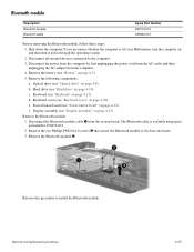
4-35 The Bluetooth cable is ...
Service Guide - Page 75
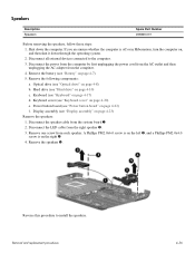
... "Power button board" on page 4-22) f. Power button board (see "Hard drive" on page 4-20) e. Disconnect the LED cable from each speaker. Optical drive (see "Keyboard cover" on page 4-10) c. Remove one screw from the right speaker 2. 3. Removal and replacement procedures
4-36 Disconnect all external devices connected to install the speakers.
Keyboard cover (see...
Service Guide - Page 76
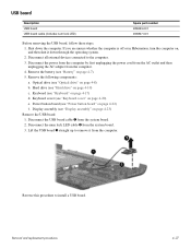
... c. Disconnect the USB board cable 1 from the computer. 4.
Removal and replacement procedures
4-37 Remove the following components: a. Hard drive (see "Keyboard cover" on page 4-22) f. Disconnect all external devices connected ...to install a USB board. Keyboard cover (see "Hard drive" on page 4-17) d. Disconnect the num lock LED cable 2 from the ...
Service Guide - Page 77

Optical drive (see "Hard drive" on page 4-8) b. Hard drive (see "Optical drive" on page 4-10) c. Display assembly (see "Power button board" on page 4-23)
Removal and replacement procedures
4-38 includes built-in modem, Digital Media 498462-001 Slot, and replacement thermal material)
UMA system board, NVIDIA (for Presario only; Shut down through the operating system. 2. ...
Service Guide - Page 80
... part number 489126-001
489154-001
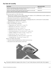
Before removing the fan, follow these steps: 1.
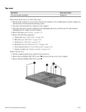
Disconnect all external devices connected to the computer. 3. Remove the following components: a. Hard drive (see "Top cover" on page 4-10) c. Top cover (see "Hard drive" on page 4-30) h. Disconnect the fan cable from the computer. 4. Removal and replacement procedures
4-41
Service Guide - Page 83
...2. Remove the following components: a. Keyboard cover (see "Optical drive" on page 4-20) f. Optical drive (see "Keyboard cover" on page 4-8) c. Hard drive (see "Keyboard" on page 4-10) d. Keyboard (see "Hard drive" on page 4-17) e. b. Power button board (see "Battery" on page 4-22)
Removal and replacement procedures
4-44 Disconnect the power from the computer by first...
Service Guide - Page 85
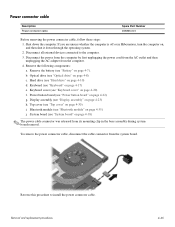
...the computer. 3. Disconnect all external devices connected to install the power connector cable. Keyboard cover (see "Hard drive" on page 4-30) i.
Hard drive (see "Keyboard cover" on page 4-22) g. Top cover (see "Display assembly" on page 4-17) e.
Removal and replacement procedures
4-46 b. To remove the power connector cable, disconnect the cable connector from the computer...
Service Guide - Page 133
...
spare part number 3-5, 3-17, 4-36
specifications Blu-ray ROM DVD±RW SuperMulti DL Drive 6-4 display 6-2 DVD±RW and CD-RW SuperMulti Double-Layer Combo Drive 6-3 DVD±RW and CD-RW SuperMulti Double-Layer Combo Drive with LightScribe 6-4 hard drive 6-2 I/O addresses 6-6 interrupts 6-5 memory map 6-7 system DMA 6-5
system backup 8-1 system board
removal 4-39 spare...
Similar Questions

How To Replace Hard Drive In Probook 4720s
(Posted by karph 9 years ago)


Can I Purchase A Replacement Screen For This Laptpop (hp G60 121wm)
The inside of the sceeen is cracked. Can the screen be replaced?
The inside of the sceeen is cracked. Can the screen be replaced?
(Posted by mylesrachel 10 years ago)

Can I Change The Cpu Of My Laptop Hp G60 Ft468ua Into Dual Core And Which One
(Posted by licdunit 11 years ago)