HP Color LaserJet CM6040/CM6030 MFP Series - Job Aid - Maintenance
Page 1
... until it snaps into the printer. Close the tray door. 1 2 3 4 ©2008 Copyright Hewlett-Packard Development Company, L.P. 1 www.hp.com HP Color LaserJet CM6030 and CM6040 MFP Series Maintenance Load trays, replace print cartridges, replace image drums, and clear jams How do I Load Tray 1. NOTE: For Letter Rotated and A4 Rotated sizes, place the side to...
... until it snaps into the printer. Close the tray door. 1 2 3 4 ©2008 Copyright Hewlett-Packard Development Company, L.P. 1 www.hp.com HP Color LaserJet CM6030 and CM6040 MFP Series Maintenance Load trays, replace print cartridges, replace image drums, and clear jams How do I Load Tray 1. NOTE: For Letter Rotated and A4 Rotated sizes, place the side to...

HP Color LaserJet CM6040/CM6030 MFP Series - Job Aid - Maintenance
Page 10
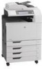
... on the image drum box. Remove the new image drum from its slot and insert the image drum until it is on the sides of the product, while supporting the image drum with its packaging (3). Align the image drum with your other hand. (2). Store the used image drum in a protective bag. HP Color LaserJet CM6030 and CM6040 MFP Series Maintenance...
... on the image drum box. Remove the new image drum from its slot and insert the image drum until it is on the sides of the product, while supporting the image drum with its packaging (3). Align the image drum with your other hand. (2). Store the used image drum in a protective bag. HP Color LaserJet CM6030 and CM6040 MFP Series Maintenance...

HP Color LaserJet CM6040/CM6030 MFP Series - Job Aids - Replace Image Drums
Page 1
... gray roller cover on the bottom of the front door and pull down to perform Replace image drums. Replace an image drum when the control panel displays the Replace Drum message. HP Color LaserJet CM6030 and CM6040 MFP Series Manage and Maintain Replace image drums How do I Steps to open (1). 2 With one hand, slowly pull the used image...
... gray roller cover on the bottom of the front door and pull down to perform Replace image drums. Replace an image drum when the control panel displays the Replace Drum message. HP Color LaserJet CM6030 and CM6040 MFP Series Manage and Maintain Replace image drums How do I Steps to open (1). 2 With one hand, slowly pull the used image...
HP Color LaserJet CM6030/CM6040 MFP Series - Software Technical Reference (external)
Page 29
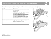
.../scan/fax originals 4 ADF output bin 5 Right door (provides access to the transfer unit, transfer roller, and fuser unit) 6 On/Off switch 7 Lower right door 8 HP Color LaserJet CM6030 MFP and HP Color LaserJet CM6040 MFP: Trays 2 and 3 HP Color LaserJet CM6030 f MFP and HP Color LaserJet CM6040f MFP: Trays 2, 3, 4 and 5 9 Front cover (provides access to print cartridges and image drums) 10 Output bin ENWW Product walkaround 9
.../scan/fax originals 4 ADF output bin 5 Right door (provides access to the transfer unit, transfer roller, and fuser unit) 6 On/Off switch 7 Lower right door 8 HP Color LaserJet CM6030 MFP and HP Color LaserJet CM6040 MFP: Trays 2 and 3 HP Color LaserJet CM6030 f MFP and HP Color LaserJet CM6040f MFP: Trays 2, 3, 4 and 5 9 Front cover (provides access to print cartridges and image drums) 10 Output bin ENWW Product walkaround 9

Service Manual
Page 7
... on non-HP print cartridges 103 HP fraud hotline and Web site 103 Replace supplies ...104 Locate supplies ...104 Supply replacement guidelines 104 Approximate replacement intervals for supplies 105 Change print cartridges 105 Change image drums ...108 Install memory ...111 Install DDR memory DIMMs 111 Enable ...memory 114 Enable memory for Windows 2000 and XP 114 Install an HP Jetdirect or EIO print server card or EIO hard disk 115...
... on non-HP print cartridges 103 HP fraud hotline and Web site 103 Replace supplies ...104 Locate supplies ...104 Supply replacement guidelines 104 Approximate replacement intervals for supplies 105 Change print cartridges 105 Change image drums ...108 Install memory ...111 Install DDR memory DIMMs 111 Enable ...memory 114 Enable memory for Windows 2000 and XP 114 Install an HP Jetdirect or EIO print server card or EIO hard disk 115...
Service Manual
Page 9
...charging 162 Step 3: Laser-beam exposure 163 Step 4: Development 163 Step 5: Primary transfer 164 Step 6: Secondary transfer 164 Step 7: Separation 165 Step 8: Fusing 165 Step 9: ITB cleaning 166 Step 10: Drum cleaning 166 Print cartridge ...167 Imaging drum ...168 Developing roller ...engagement and disengagement 170 Intermediate transfer belt (ITB) unit 171 Primary-transfer-roller engagement and disengagement 171 ITB unit detection 173 Secondary-transfer-roller unit 175 Calibration ...175 Color-...
...charging 162 Step 3: Laser-beam exposure 163 Step 4: Development 163 Step 5: Primary transfer 164 Step 6: Secondary transfer 164 Step 7: Separation 165 Step 8: Fusing 165 Step 9: ITB cleaning 166 Step 10: Drum cleaning 166 Print cartridge ...167 Imaging drum ...168 Developing roller ...engagement and disengagement 170 Intermediate transfer belt (ITB) unit 171 Primary-transfer-roller engagement and disengagement 171 ITB unit detection 173 Secondary-transfer-roller unit 175 Calibration ...175 Color-...
Service Manual
Page 11
...264 Lifter-drive unit ...266 Fuser motor ...269 Intermediate-transfer belt (ITB) motor 270 Face-down output bin ...271 Left cover ...272 Laser/scanner fan duct ...273 Print-cartridge driver PCA 275 High-voltage power supply PCA (B 277 Formatter case ...279 DC controller PCA ...281 Environmental... sensor ...283 Image-drum motor ...284 Fuser fan ...286 Print-cartridge feed motor (black 287 Print-cartridge feed motor (yellow, magenta, and cyan 288 Cartridge fan unit ...289 Laser/scanner fan unit ...290 Fuser power-supply unit 291 Primary ...
...264 Lifter-drive unit ...266 Fuser motor ...269 Intermediate-transfer belt (ITB) motor 270 Face-down output bin ...271 Left cover ...272 Laser/scanner fan duct ...273 Print-cartridge driver PCA 275 High-voltage power supply PCA (B 277 Formatter case ...279 DC controller PCA ...281 Environmental... sensor ...283 Image-drum motor ...284 Fuser fan ...286 Print-cartridge feed motor (black 287 Print-cartridge feed motor (yellow, magenta, and cyan 288 Cartridge fan unit ...289 Laser/scanner fan unit ...290 Fuser power-supply unit 291 Primary ...
Service Manual
Page 16
... tests ...592 Component test (special-mode test 592 Transfer-motors test 592 Belt-only test 592 Image-drum motors test 592 CMYK-laser test 593 Fuser-motor test 593 Fuser pressure-release motor test 593 Color-alienation motor test 593 ITB-contact/alienation test 593 Paper-transport motor test 594 Tray-1 pickup-solenoid...
... tests ...592 Component test (special-mode test 592 Transfer-motors test 592 Belt-only test 592 Image-drum motors test 592 CMYK-laser test 593 Fuser-motor test 593 Fuser pressure-release motor test 593 Color-alienation motor test 593 ITB-contact/alienation test 593 Paper-transport motor test 594 Tray-1 pickup-solenoid...
Service Manual
Page 29
...Figure 5-5 Fuser temperature-control circuit 151 Figure 5-6 Low-voltage power-supply circuit 154 Figure 5-7 High-voltage power supply circuits 156 Figure 5-8 Laser/scanner system ...158 Figure 5-9 Image-formation system ...160 Figure 5-10 Image-formation process ...161 Figure 5-11 Pre-exposure ...162 Figure ...5-17 Separation ...165 Figure 5-18 Fusing ...165 Figure 5-19 ITB cleaning ...166 Figure 5-20 Drum cleaning ...166 Figure 5-21 Print-cartridge system ...167 Figure 5-22 Imaging-drum system ...169 Figure 5-23 Developing roller engagement and disengagement control 170 Figure 5-24 ITB unit ...
...Figure 5-5 Fuser temperature-control circuit 151 Figure 5-6 Low-voltage power-supply circuit 154 Figure 5-7 High-voltage power supply circuits 156 Figure 5-8 Laser/scanner system ...158 Figure 5-9 Image-formation system ...160 Figure 5-10 Image-formation process ...161 Figure 5-11 Pre-exposure ...162 Figure ...5-17 Separation ...165 Figure 5-18 Fusing ...165 Figure 5-19 ITB cleaning ...166 Figure 5-20 Drum cleaning ...166 Figure 5-21 Print-cartridge system ...167 Figure 5-22 Imaging-drum system ...169 Figure 5-23 Developing roller engagement and disengagement control 170 Figure 5-24 ITB unit ...

Service Manual
Page 32
...-drum motor (3 of 3 285 Remove the fuser fan ...286 Remove the print-cartridge feed motor (black 287 Remove the print-cartridge feed motor (yellow, magenta, and cyan 288 Remove the cartridge fan unit (1 of 2 289 Remove the cartridge fan unit (2 of 2 289 Remove the laser/......309 Remove front door ...310 Remove front door assembly ...311 Remove the color-misregistration and image-density sensor unit (1 of 3 312 Remove the color-misregistration and image-density sensor unit (2 of 3 313 Remove the color-misregistration and image-density sensor unit (3 of 3 313 Remove the pressure-release...
...-drum motor (3 of 3 285 Remove the fuser fan ...286 Remove the print-cartridge feed motor (black 287 Remove the print-cartridge feed motor (yellow, magenta, and cyan 288 Remove the cartridge fan unit (1 of 2 289 Remove the cartridge fan unit (2 of 2 289 Remove the laser/......309 Remove front door ...310 Remove front door assembly ...311 Remove the color-misregistration and image-density sensor unit (1 of 3 312 Remove the color-misregistration and image-density sensor unit (2 of 3 313 Remove the color-misregistration and image-density sensor unit (3 of 3 313 Remove the pressure-release...


